
Best Practices for Installing Basket Cables on Container Cranes: An Engineering Guide for Middle Eastern Port Terminals
Avoid common basket cable installation mistakes with practical guidance on hanging length, weight distribution, bending radius, and cable twist control.
hongjing.Wang@Feichun
7/10/202614 min read
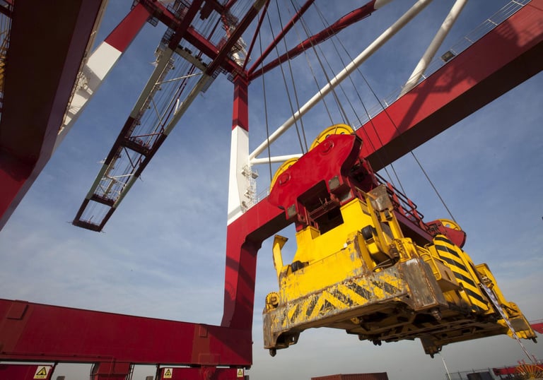
In the high-intensity maritime hubs of the Middle East—stretching from the automated container berths of Jebel Ali in Dubai and King Abdullah Port in Rabigh to the major transshipment gateways of Salalah in Oman and Khalifa Port in Abu Dhabi—Ship-to-Shore (STS) cranes operate under demanding performance schedules. Within these massive engineering systems, the spreader unit handles the rapid, repetitive lifting, positioning, and locking of container boxes. The electrical lifeline feeding this high-cycle operation is the spreader basket cable, a highly engineered component that cannot be treated as a standard flexible industrial wire.
Unlike traditional cables routed along protective cable tracks or spooled tightly onto motorized reeling drums, spreader basket cables operate in a challenging state of vertical suspension. They are continuously exposed to the combined forces of gravity, wind-driven sway, high-speed vertical acceleration, structural torsion, and uneven dynamic loads. In the harsh environments of the Arabian Gulf and the Red Sea—where summer ambient temperatures routinely exceed 50°C, UV radiation levels are severe, and fine, abrasive desert sand is common—these mechanical stresses are heavily compounded.
If a basket cable is installed incorrectly, these harsh conditions will rapidly accelerate mechanical wear, leading to premature cable failure. This guide examines the engineering principles, precise installation sequences, and maintenance practices required to ensure maximum operational life for vertical container crane basket cables. It focuses on practical steps to eliminate common installation errors that lead to costly unplanned terminal downtime.
1. Introduction
2. Where Basket Cables Are Used: The Spreader Interface
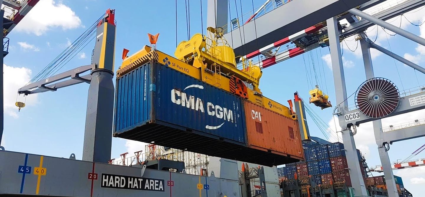
Spreader basket cables are utilized at the critical interface between the main trolley of an STS crane and the active container spreader below. As the hoist system lowers and raises the spreader to engage with container ships, the power, control, and communication lines must expand and contract smoothly within a dedicated storage enclosure known as a collector basket or gravity-feed storage bin.
Within this vertical system, the basket cable serves three primary roles:
First, it acts as the primary spreader power cable, supplying the electrical current required to drive hydraulic power units, twistlock actuators, flipper motors, and auxiliary systems on the spreader frame.
Second, it functions as the core control cable, carrying low-voltage signals that monitor twistlock engagement statuses, land-pin positions, and seating verification safety interlocks.
Third, it operates as a high-speed communication and data transmission line. Modern spreaders are equipped with closed-circuit cameras, laser sensors, and digital diagnostic modules that require continuous, interference-free fiber-optic or shielded copper data links to communicate with the crane’s central PLC system.
Basket cables are selected for crane configurations where the vertical suspension length is relatively short to moderate and the space limits of the trolley frame favor a gravity-feed vertical or near-vertical storage system over a motorized cable reel.
Because of these unique operating realities, the Port Equipment Manufacturers Association (PEMA) classifies spreader basket cables as a specialized category of crane cabling. PEMA emphasizes that because these cables lack continuous external tracking or structural support along their suspended length, they experience extreme mechanical stress. This requires highly specialized cable designs and precise installation methods.
To satisfy these rigorous demands, European and German engineering frameworks have produced dedicated heavy-duty cable types. The most notable models utilized globally and throughout Middle Eastern terminals include:
The German standard model (N)GRDGOU, which is a specialized rubber-insulated, heavy-duty flexible cable featuring an integrated anti-torsion braid, specifically designed for vertical gravity-feed basket systems.
The standard model NSHTOU, which, while frequently deployed on motorized reels, can be adapted for vertical suspension when enhanced with specialized central strain-relief elements and anti-twisting polyester layers.
The specialized model (N)TSCGEWOU, designed for medium-voltage variants where high-power delivery must be combined with high-frequency vertical flexing within a tight collector basket enclosure.
3. Basket Cable Application Photos
To visually ground these engineering principles, port installation teams should refer to three essential visual reference layouts before beginning any replacement or installation procedure:
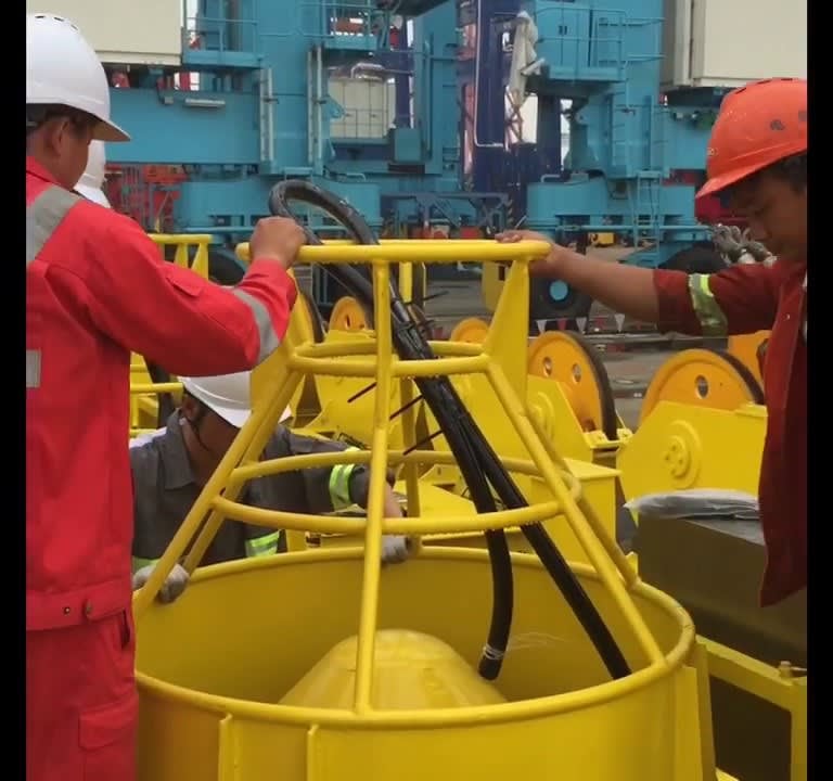
Visual Reference 1: Field Installation Photo. This layout illustrates a real-world field installation on a twin-lift container spreader, highlighting how the cable drops vertically from the trolley platform clamps directly into the center of the collector basket without rubbing against structural steel beams.
Visual Reference 2: Cable Structure Graphic. This cross-sectional view shows the interior layout of a high-performance cable like the German standard model (N)GRDGOU. It shows the fine-stranded Class 5 copper conductors, the high-density rubber insulation, the internal bedding layer, and the integrated anti-torsion textile or aramid fiber supporting braid embedded between the inner and outer sheaths.
Visual Reference 3: Basket Collector Visual. This diagram shows a gravity-feed collector basket system, illustrating how the cable should naturally loop, layer, and arrange itself inside the storage bin when the spreader is raised to its highest hoisting position.
4. Proper Hanging Length: Balancing Slack and Tension
Achieving the correct hanging length is the most critical parameter when installing a vertical suspended cable. The cable must never be installed too tight, which causes immediate over-tensioning, nor should it be allowed too much slack, which leads to uncontrolled swaying, looping, and structural snagging.
Hanging length is defined as the total amount of free vertical cable loop required to allow the full range of hoist travel without placing mechanical stress on the cable’s internal layers.
When the spreader reaches its lowest point—such as reaching deep into the hold of a large container vessel—the basket cable must retain a slight, visible catenary curve just above its lower clamping mechanism. It must never pull completely straight or act as a secondary load-bearing rope for the spreader assembly.
PEMA documentation notes that proper cable installation must protect the system from excessive tension, reverse bending, and destructive structural torsion. To achieve this, implementing reliable tension-relief loops at both the upper trolley connection point and the lower spreader connection point is essential.
Before permanently securing the upper and lower heavy-duty clamps, the cable must be allowed to settle naturally. When a new cable is delivered to a port, it arrives wrapped tightly around a wooden shipping reel, which introduces structural "shape memory" into the rubber compounds and copper strands.
If you unreel the cable and clamp it immediately into a vertical suspension system, those internal stresses will cause the cable to twist, loop unevenly, or bow sideways during operation.
The best practice for site teams is to unspool the cable completely and lay it flat on a clean yard surface for at least 24 to 48 hours. In the warm climate of the Middle East, this relaxation period allows the rubber compounds to soften slightly, neutralizing any residual storage memory and allowing the cable to hang perfectly straight before final installation.
5. Weight Distribution in the Basket: The Mechanics of Gravity Storage
When the container spreader is hoisted upward, the suspended cable feeds downward into the collector basket, gathering in a series of natural, concentric loops. The core design principle governing this system is that the total weight of the cable must be distributed evenly across the floor of the basket rather than being concentrated at a single point or forced into sharp bends.
If the collector basket is poorly positioned, or if the cable's natural twist is restricted, the cable will pile up unevenly. This creates a severe failure mechanism where localized zones carry too much mechanical load:
First, it causes local sheath compression. When weight is concentrated on a single loop at the bottom of the pile, the outer rubber jacket undergoes compression deformation, thinning the protective layer.
Second, it induces severe conductor strain. Uneven stacking causes the internal copper core conductors to shift within their insulation jackets, leading to micro-elongation.
Third, it forces the cable into uneven bending patterns. Instead of forming wide, relaxed loops, sections of the cable are forced into tight, irregular kinks under the weight of the overhead cable pile.
Fourth, it triggers premature material fatigue, causing the cable to develop micro-cracks and electrical shorts well before its rated service life.
Proper weight balance on all cable support structures is a primary installation check outlined in PEMA engineering guidance. To understand the physical forces at play, engineers can calculate the static loads using a straightforward mechanical formula:
Total Weight equals Cable Length multiplied by Cable Weight.
Consider a practical terminal installation example: An STS crane requires a free suspended basket cable length of 50 meters, and the selected heavy-duty German standard model (N)GRDGOU cable has a nominal weight of 5 kilograms per meter.
Applying the formula: 50 meters multiplied by 5 kilograms per meter equals 250 kilograms of total suspended mass.
To determine the static gravitational force acting on the upper mounting clamps, convert this mass into Newtons using the standard acceleration of gravity, which is 9.81 meters per second squared: 250 kilograms multiplied by 9.81 meters per second squared equals 2452.5 Newtons, which translates to approximately 2.45 kilonewtons (kN), or roughly 2.5 kN of continuous static vertical load.
When the hoist accelerates upward at speeds reaching 120 to 180 meters per minute, this static load combines with dynamic inertia forces, easily doubling or tripling the instantaneous tension experienced by the upper clamps and the cable core. If the weight is not properly supported and distributed inside the storage basket during the downward cycle, these forces will quickly cause structural failure.
6. Common Installation Mistakes: A Troubleshooting Field Guide
By identifying and addressing the most common field installation errors, port engineering departments can use this guide as a preventative troubleshooting tool.
Error 1: Too Tight Installation
This error occurs when installation teams fail to allocate sufficient slack or miscalculate the loop geometry needed for full vertical hoist travel. As a result, when the spreader descends to its lowest operational limit, the suspended section experiences excessive tension. This over-tensioning causes rapid conductor elongation, thins out the internal insulation layers, and significantly reduces the cable's operational life.
Error 2: Small Bending Radius
This mistake happens when the cable is forced into a tighter curve than recommended by VDE and IEC standards, usually near the entry guide rollers or inside the collector basket rim. Forcing a heavy-duty cable into an unapproved curve creates intense conductor fatigue and severe insulation stress. Over time, this leads to cracked insulation layers and internal short circuits, even if the outer rubber jacket looks undamaged from the outside. PEMA explicitly warns that bending beyond the recommended minimum radius is a primary driver of premature cable failure.
Error 3: Cable Twisting and Torsional Straining
This error occurs when a cable is twisted along its longitudinal axis during installation, often because it was pulled improperly off the shipping reel or wasn't allowed to relax before clamping. This locked-in torsion causes severe internal conductor damage and sets up shape memory stresses. As the spreader moves up and down, the cable will loop unevenly, exhibit "corkscrewing" deformations, and eventually suffer broken conductor strands. PEMA lists twisting and torsion caused by misaligned guides, rollers, and storage bins as leading causes of structural cable damage.
Error 4: Wrong Clamp Position
This mistake involves applying the heavy-duty strain-relief clamps too close to a high-stress bending zone or using incorrect torque spacing. When a clamp is positioned improperly or over-tightened, it causes severe sheath damage and localized compression. This crushes the internal bedding layers, leading to rapid jacket wear, outer rubber cracking, and exposure of the internal copper cores to water and salt air.
7. Correct Installation Practice: Step-by-Step Field Procedure
To maximize cable longevity, site teams must follow a disciplined, step-by-step installation sequence. The cable must always be guided smoothly into position, never forced or twisted.
[Unwind Tangentially] ──► [Lay Flat to Relax] ──► [Feed Top-to-Bottom] ──► [Align Natural Lay] ──► [Perform Test Cycles]
Step 1: Tangential Unwinding
Never pull a cable off a shipping reel sideways, as this introduces a permanent twist into the core conductors for every turn removed from the spool. Instead, place the reel on a heavy-duty axle or mechanical turntable and unwind the cable tangentially. The reel must rotate smoothly in perfect synchronization with the pull to prevent loops or kinks.
Step 2: Structural Relaxation
As noted previously, lay the unwound cable completely flat on a clean yard surface. In the Middle Eastern climate, letting the cable sit in the sun for 24 to 48 hours allows the internal layers to settle, releasing residual manufacturing and storage stresses.
Step 3: Top-to-Bottom Feeding
Always feed the cable into the crane system from top to bottom. Secure the upper termination point at the trolley platform first, using a wide, rounded strain-relief clamp or a properly sized wire mesh grip. Allow the remaining length to hang naturally down toward the basket under its own weight, ensuring it does not strike any structural steelwork during the process.
Step 4: Aligning the Natural Lay
As the cable enters the gravity-feed storage basket, guide it so it follows its natural manufactured lay. Do not force the cable into a specific direction if it shows a natural tendency to loop a certain way. Adjust the lower clamp alignment on the spreader frame to match this natural orientation, ensuring the system is completely free of torsional stress.
Step 5: Post-Installation Testing and Verification
Once all clamps are secured to the correct torque specifications, perform a complete, slow test cycle before commissioning the crane for commercial service. Hoist and lower the spreader through its entire travel range at reduced speed.
During this test, team members must closely watch the cable's behavior to confirm it moves freely, forms smooth loops inside the basket, and shows no signs of twisting, bowing, or surface scraping against the guide rims. Any identified looping or twisting must be corrected immediately by loosening the clamps and adjusting the cable's alignment.
8. Load and Stress Diagram Section: Visualizing the Physics
Understanding the physical forces inside a vertical basket cable is much easier when you can visualize how stress distributes across the system. Engineers should visualize the following three conceptual structural diagrams:
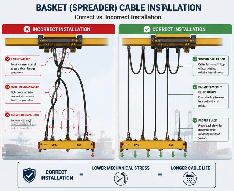
Diagram 1: Wrong Installation versus Correct Installation
This diagram highlights the stark structural contrast between poor and proper installation geometry. On the faulty side, the cable is clamped tightly with zero slack allowance, causing the entire vertical load to pull directly against the top fitting.
On the correct side, the cable features a generous, relaxed tension-relief loop at the top and bottom terminations. This layout ensures the static weight of the cable rests evenly on the floor of the collector storage basket when the spreader is raised, leaving the clamping points free from excessive tension.
Diagram 2: Cable Stress Distribution Diagram
This diagram maps out where mechanical forces concentrate along the cable run. In a poorly aligned system, high-stress zones show up as intense pressure points right at the sharp edge of the upper clamp and along tight kinks inside the basket storage bin.
In a correctly aligned system, the stress profile is low and evenly distributed along the entire length of the cable, showing no sharp force spikes or concentrated friction zones.
Diagram 3: Basket Cable Structure and Suspension Behavior
This diagram illustrates the internal components of a high-performance vertical cable, such as the German standard model (N)GRDGOU series. It shows how the thick outer rubber jacket, the integrated anti-torsion textile braid, and the internal bedding layer work together.
The diagram demonstrates how this composite structure absorbs longitudinal pulling forces, shielding the inner Class 5 copper conductors from stretching or twisting even during rapid vertical acceleration.
9. Why Basket Cable Installation Fails in Practice: The Structural Failure Chain
When a spreader cable fails early in the field, port operators often assume it was caused by a manufacturing defect or low-quality materials. However, systematic field investigations show that most premature failures stem from installation errors that set off a destructive failure chain.
The failure chain typically follows this sequence:
First, an incorrect hanging geometry or misaligned storage basket introduces a slight, permanent twist into the cable run during installation.
Second, this locked-in torsion prevents the cable from looping smoothly, causing its total weight to distribute unevenly inside the gravity basket.
Third, the lack of sufficient operating slack subjects the suspended section to continuous over-tensioning during high-speed hoist movements.
Fourth, these forces cause the internal components to shift, concentrating mechanical stress on the outer rubber jacket and crushing it against structural guide rims.
Fifth, this localized pressure leads to deep clamp damage, jacket tearing, and micro-cracking across the outer sheath.
Finally, the copper conductors suffer rapid fatigue under repeated spreader movements, resulting in a broken cable, electrical short circuits, and sudden crane failure.
PEMA's general engineering guidance for moving crane cables strongly supports this analysis. It shows that improper storage, careless handling, and poor installation methods are the primary causes of early operational failures.
Many "cable quality" complaints are actually down to installation errors where the cable was forced into a tight layout rather than being allowed to guide itself naturally. In the extreme heat and humidity of Middle Eastern ports, these installation flaws cause rubber compounds to degrade and break down much faster.
10. Real Case Reference: Lessons from the Field
To better understand these risks, port maintenance teams can look to real-world incidents where poor spooling, improper tension control, and sudden line releases led to severe mechanical failures in heavy rigging and hoisting setups.
A detailed technical discussion covering these issues can be found on the Heavy Equipment Forums at this link: https://www.heavyequipmentforums.com/threads/failed-becket.66459/
This specific forum thread details how an improperly secured line or a failed becket component can trigger sudden line releases, severe twisting, and destructive load shocks throughout a high-stress rigging system.
While that case focuses on heavy crane wire ropes and line sockets, the underlying engineering lessons apply directly to vertical spreader basket cables.
When an installation team over-tightens a cable clamp, allows a basket cable to twist, or fails to calibrate the vertical tension relief loops correctly, the system experiences similar destructive force spikes during high-speed operation.
The sudden mechanical shocks and twisting described in the forum mirror what happens inside a rubber basket cable when it snags on a basket rim and suddenly snaps free. These field cases prove that small errors in securing and aligning a cable line can quickly lead to major structural failures under heavy loads.
Additionally, port engineering teams can review official PEMA technical guides and look up field installation videos for ZPMC spreader cable systems. These practical resources show how leading global port authorities organize their installation procedures, emphasizing the importance of keeping the cable completely untwisted and properly aligned within the vertical collector basket.
11. Installation Checklist for Site Teams: Pre-Commissioning Protocol
Before signing off on a new spreader basket cable installation and restarting commercial container operations, the terminal’s maintenance supervisor must personally verify each item on this pre-commissioning checklist:
Proper Hanging Length: Check that the cable retains a visible, relaxed catenary curve at the lowest point of hoist travel, ensuring it is never pulled completely straight or subjected to tension.
Loop Symmetry: Verify that the cable forms clean, even, concentric loops inside the collector basket as the spreader ascends, showing no signs of overlapping or kinking.
Correct Clamp Position: Confirm that all heavy-duty upper and lower strain-relief clamps are installed with the correct spacing and tightened to the manufacturer's exact torque specifications to avoid crushing the jacket.
Zero Cable Torsion: Visually inspect the entire vertical length of the cable to ensure it hangs perfectly straight without any signs of twisting, spiraling, or corkscrewing.
Minimum Bending Radius: Use a radius gauge to verify that the cable is never forced into a curve tighter than its certified limit (such as 5 to 6.25 times the outer diameter for the Feichun Crane NSHTOU series) near guide rollers or basket rims.
Free Mechanical Movement: Run the container spreader through several full hoist cycles at reduced speed to confirm the cable feeds into and out of the basket smoothly without catching.
Zero Sheath Scuffing: Inspect the outer rubber jacket after the initial test cycles to ensure there are no signs of surface scraping, pinching, or localized wear against structural steel components.
PEMA engineering guidelines emphasize that optimizing all critical dimensions, guide positions, and system geometries together is the only reliable way to prevent uneven wear and premature cable failure.
12. Conclusion: Guided, Not Forced
The operational life of a container crane spreader basket cable is determined largely by the quality of its initial installation. Even the most advanced, premium German standard cables—such as the tinned-copper reinforced (N)GRDGOU series or the ruggedized NSHTOU family—will fail early if subjected to incorrect geometry, locked-in torsion, or poor weight distribution.
By implementing disciplined installation practices, allowing new cables to relax flat before mounting, and carefully checking hanging lengths and clamp positions, port operators can prevent the vast majority of early cable failures.
In the demanding port environments of the Middle East, maintaining this level of engineering discipline is essential for ensuring high terminal productivity. In any vertical gravity-feed spreader basket system, the gold standard rule for maintenance teams remains: the cable must be guided smoothly through its path, never forced into position.
Port crane cables | Mining cables | Reeling cables | Trailing cables | Festoon cables | Heavy-duty power cables | Medium voltage cables | Offshore crane cables | Underground mining cables | Dragline cables | Shearer cables | Container handling cables | STS crane cables | RTG cables | Mobile equipment cables | Armored cables | Flexible power cables | VFD cables | Submersible cables | Cold resistant cables | Abrasion resistant cables | Flame retardant cables | Marine environment cables | Opencast mining | Underground operations
© 2006 All rights reserved.
[INDUSTRIAL_CABLES]
INDUSTRIAL GRADE CABLE SYSTEMS | PORT & MINING SOLUTIONS
TEL: +86 153 7530 2641 |MAIL: hongjing.Wang@feichuncables.com