BS 7671 IET Wiring Regulations: Cable Selection Criteria for Industrial Plants in Oman and UAE
Explore BS 7671 cable selection criteria for industrial plants in Oman and the UAE, including temperature derating, UV resistance, mechanical protection, and fire safety.
hongjing.Wang@Feichun
7/14/202624 min read

1. Introduction
In the global landscape of industrial engineering, infrastructure projects in the Gulf Cooperation Council (GCC) region—particularly in the Sultanate of Oman and the United Arab Emirates (UAE)—present some of the most demanding environmental and operational challenges in the world. As these nations rapidly expand their industrial footprints across oil and gas downstream facilities, massive commercial ports, deep-water desalination plants, and heavy mining operations, the reliability of their electrical infrastructure becomes paramount.
At the heart of any robust electrical infrastructure lies the critical process of cable selection and sizing. For decades, international EPC (Engineering, Procurement, and Construction) contractors, principal consultants, and design engineers operating within the Middle East have required a highly rigorous, standardized framework to guide their electrical designs. This is where BS 7671, formally known as the IET Wiring Regulations (Institution of Engineering and Technology), enters the equation.
Serving as the foundational backbone for electrical installation design in the United Kingdom, BS 7671 has established itself globally as a premier benchmark for calculating cable cross-sectional areas, evaluating installation methods, and ensuring fundamental electrical safety. The current framework, BS 7671:2018+A2:2022, represents the latest evolution of these regulations, incorporating modern safety methodologies, updated current-carrying capacity metrics, and refined requirements for fire safety performance.
While BS 7671 is inherently a British standard, its mathematical logic, thermodynamic principles, and structured installation methodologies are extensively referenced across Oman and the UAE. Local municipal authorities, government ministries, and mega-project consultants frequently turn to BS 7671 logic as a dependable reference point. This is particularly true when engineers must assess how a specific cable will behave under severe thermal conditions, how heavily it must be derated due to mutual heating in dense cable trays, and how its insulation will hold up over a projected 25-year to 30-year operational lifespan.
However, a direct, unadjusted application of standard UK electrical design practices to the Middle East can result in catastrophic operational failures. The core engineering problem addressed in this article centers on a practical, high-stakes question: How should engineers effectively select and size power, control, and instrumentation cables for Middle Eastern industrial plants, where ambient heat, intense ultraviolet (UV) radiation, and extreme mechanical stresses are vastly more severe than in the temperate climate for which BS 7671 was originally compiled?
By analyzing the structured methodology of the IET Wiring Regulations and adapting its core formulas and derating tables to the realities of the Gulf environment, engineering teams can bridge the gap between theoretical compliance and long-term field reliability. This comprehensive guide details the practical physics of cable performance under intense environmental stress, providing a clear blueprint for robust electrical design in the region.
2. What BS 7671 Is
To appreciate the value of BS 7671 in international procurement and engineering design, it is first necessary to define its exact nature and scope. BS 7671 is the British Standard for Electrical Installations, developed jointly by the British Standards Institution (BSI) and the Institution of Engineering and Technology (IET). Recognized universally as the IET Wiring Regulations, this document is not merely a collection of vague suggestions; it is a highly detailed, legally recognized framework in the United Kingdom that governs how electrical systems must be designed, selected, erected, inspected, tested, and maintained.
The scope of BS 7671 is comprehensive. It encompasses everything from the point of supply delivery down to the smallest final sub-circuit in a facility. It provides strict mandates on the selection and erection of electrical equipment, ensuring that every component—from main low-voltage switchboards and distribution boards to the minute details of containment systems—is fully compatible with its environment and intended duty cycle. Furthermore, it covers the intricate mechanics of wiring systems and dictates the necessary protective measures required to mitigate risks against electric shock, thermal effects, overcurrent, voltage drops, and electromagnetic disturbances.
Although deeply rooted in the statutory framework of the UK, the engineering logic embedded within BS 7671 is utilized worldwide as a prestigious specification benchmark. The reason for its global adoption lies in its uncompromising alignment with broader international engineering standards. BS 7671 is heavily harmonized with CENELEC (European Committee for Electrotechnical Standardization) requirements and, most importantly, with the International Electrotechnical Commission’s IEC 60364 series, which governs low-voltage electrical installations globally. Consequently, when an engineer uses BS 7671, they are inherently operating within an internationally recognized, scientifically validated framework.
For the specific task of cable selection, BS 7671 is uniquely valuable because it creates an absolute, unbreakable thermodynamic link between real-world installation conditions, safety margins, and the physical current-carrying capacity (ampacity) of a conductor. Rather than letting engineers rely on simplistic catalog ratings provided by manufacturers—which are typically calculated under idealized laboratory conditions—BS 7671 forces the designer to look at the exact physics of the cable's future home.
It provides an explicit mathematical structure where the base current-carrying capacity of a core conductor is systematically modified by a sequence of correction factors. These factors account for the surrounding air or soil temperature, the proximity of adjacent cables, the presence of thermal insulation, the type of overcurrent protective device being used, and the exposure to direct solar radiation. By integrating all of these dynamic operational variables into a single, predictable design flow, BS 7671 ensures that the selected cable will never exceed its maximum permissible operating temperature under full-load or short-circuit conditions, thereby safeguarding lives, property, and industrial continuity.
3. Why Oman and UAE Use It
The widespread adoption of BS 7671 and its associated IEC principles across the United Arab Emirates and the Sultanate of Oman is a direct result of the historical evolution of the region's industrial sector. During the early phases of industrialization and infrastructure building in the Gulf, major master planning projects, petrochemical facilities, and utility networks were designed by international engineering consultancies, many of which were headquartered in the UK or operated under British-derived engineering methodologies. Over the decades, this institutional preference crystallized into formal regulatory frameworks. Today, project specifications in both the UAE and Oman are heavily driven by code compliance, strict consultant requirements, and rigorous utility authority mandates.
In the United Arab Emirates, the electrical engineering landscape is shaped by powerful, highly organized municipal utility authorities. In Dubai, the Dubai Electricity and Water Authority (DEWA) maintains absolute jurisdiction over electrical connectivity and compliance. Similarly, the Abu Dhabi Distribution Company (ADDC) in the capital, and the Sharjah Electricity, Water and Gas Authority (SEWA) in Sharjah, enforce highly detailed regulatory frameworks. These authorities are universally associated with code-driven electrical compliance.
When a design team submits an electrical design layout, single-line diagrams, or cable sizing calculation sheets to DEWA or ADDC for building permits and grid-connection approvals, the underlying calculations must conform to strict standards. Project specifications developed by tier-one consultants for UAE infrastructure explicitly align with IEC-based or British-style cable selection practices. The utility regulations themselves frequently adopt the exact terminology, sizing methodologies, and safety descriptors used in BS 7671, ensuring that all electrical work maintains a uniform, high level of safety and reliability.
In the Sultanate of Oman, the industrial and infrastructure sectors operate under a matching set of strict utility and operator requirements. The transmission and distribution networks are governed by entities like the Oman Electricity Transmission Company (OETC) and Nama Group, which oversee the stable delivery of power across the nation. In the country’s vast oil, gas, and mineral extraction zones, Petroleum Development Oman (PDO) acts as the premier regulatory and operating authority.
For projects executed under the jurisdiction of PDO or OETC, compliance with recognized international wiring and installation standards is mandatory. Contractors cannot simply install cables based on arbitrary commercial choices. Every cable route, termination box, and distribution system must feature documented compliance with British or IEC standards to prove it can withstand the electrical demands and environmental hazards typical of Omani industrial sites.
In practical terms, the daily workflow of consultants, design engineers, and Engineering, Procurement, and Construction (EPC) contractors across the Gulf region relies on the joint application of BS 7671 and IEC principles. When sizing a main low-voltage feeder cable for a new industrial facility in Muscat or an automated terminal in Jebel Ali, the engineering team does not invent a new sizing methodology. Instead, they utilize the standardized formulas found in the IET Wiring Regulations to calculate thermal derating, size protective conductors (earth wires), configure overcurrent protection coordination, and select the appropriate installation methods—whether the cables are laid in open-mesh trays, drawn through buried high-density polyethylene (HDPE) ducts, or routed via concrete trenches. This adherence to a common technical language allows global supply chains to deliver verified, high-performance electrical components to the Middle East with minimal friction.
4. Middle East Cable Challenges
To successfully implement the principles of BS 7671 in the Gulf, one must understand the unique physical realities of the local environment. Industrial plants in Oman and the UAE are exposed to ambient climatic conditions that are drastically more aggressive than those encountered in Western Europe or North America. The geographic location of the Arabian Peninsula results in a combination of extreme thermal loading, intense solar radiation, high humidity, and mechanical hazards that can rapidly destroy standard commercial-grade electrical components.
The most prominent challenge is the ambient temperature. While standard international cable catalogs routinely base their baseline current-carrying capacities on an assumed ambient air temperature of 30°C and a soil temperature of 20°C, outdoor ambient air temperatures in industrial zones like Sohar, Duqm, Ruwais, or Mussafah routinely climb to 45°C or 50°C during the summer months. Inside unventilated plant rooms, metal enclosures, or on exposed rooftops, local air temperatures can easily reach 60°C or 65°C.
Because of this intense environmental baseline heat, a cable's ability to dissipate the internal thermal energy generated by its current flow is severely compromised. Therefore, cable performance must be systematically verified under real, worst-case site conditions, rather than relying blindly on idealized catalog ratings.
Beyond ambient air temperature, several other severe environmental vectors must be accounted for in the engineering design:
Direct Sun Exposure and Solar Heat Gain: Cables routed along outdoor structures, open pipe racks, or industrial roof spaces are subjected to intense, continuous sunlight. This solar radiation causes significant localized heat gain, raising the conductor temperature well above the surrounding air temperature.
Intensive UV Radiation: The Solar UV Index in the Gulf region routinely reaches extreme levels. This constant exposure accelerates the chemical breakdown of standard polymers, leading to the embrittlement, cracking, and eventual disintegration of non-stabilized cable sheaths.
Mechanical Movement and Physical Abuse: Industrial environments—such as container ports, shipyards, automated bulk handling yards, and aggregate mining facilities—subject cables to continuous bending, pulling, crushing, and abrasive forces.
Corrosive Coastal Humidity: Many mega-projects are located immediately adjacent to the sea. The combination of high humidity and airborne salinity creates a highly corrosive environment that attacks exposed metal supports, unsealed cable entries, and poorly chosen jacketing materials.
Strict Fire Safety Expectations: Modern industrial plants demand high performance from emergency shutdown systems, fire pumps, and control loops. Cables must be specified to prevent the spread of flames, minimize smoke density, and eliminate toxic acid gas emissions during an emergency.
Because of these complex variables, the exact same cable type, featuring identical copper cross-sections and insulation compound codes, will perform differently depending on where and how it is installed. A cable that operates coolly and safely inside an air-conditioned control building will face rapid thermal aging, insulation failure, or physical breakdown if it is routed across an exposed outdoor cable tray or buried directly in hot, dry, non-cohesive desert soil. Engineers must analyze each segment of a cable run independently, applying specific engineering corrections for every distinct environment the cable passes through.
5. Ambient Temperature and Derating
The thermodynamic reality of an electrical cable is straightforward: current passing through a metallic conductor generates heat due to the natural resistance of the metal, a phenomenon known as Joule heating ($I^{2}R$ losses). For a cable to operate safely and indefinitely, the heat generated internally must be continuously transferred out into the surrounding environment. This thermal dissipation continues until the cable reaches a stable operating temperature.
The maximum safe operating temperature is determined entirely by the thermal limits of the insulation material wrapped around the core conductor. For standard cross-linked polyethylene (XLPE) or high-grade rubber insulation, this maximum continuous limit is typically 90°C. For standard polyvinyl chloride (PVC) insulation, the limit is lower, at 70°C.
In the Middle East, managing this thermal equation is a primary challenge for electrical engineers. Because ambient air temperatures in industrial environments routinely reach 40°C to 50°C, the thermal gradient—the difference between the maximum allowed conductor temperature (e.g., 90°C) and the surrounding air temperature—is significantly smaller than in temperate climates.
If a cable is loaded to its full nominal rating in an ambient environment of 50°C, the lack of effective heat dissipation will cause the internal core temperature to quickly exceed the 90°C threshold. This triggers accelerated thermal degradation of the polymer chains within the insulation, causing it to become brittle, crack, lose its dielectric strength, and ultimately lead to a catastrophic short-circuit or electrical fire.
To prevent this, thermal design for any industrial facility in Oman or the UAE must follow recognized installation principles, such as those found in IEC-based methods and BS 7671 cable rating logic. BS 7671 addresses this thermal hazard by mandating the application of explicit temperature correction factors (designated as $C_{a}$ factors).
When the ambient temperature surrounding an installation exceeds the standard reference baseline of 30°C for air, the designer must multiply the nominal current-carrying capacity ($I_{t}$) by the appropriate correction factor. This process systematically reduces the allowable current-carrying capacity of the conductor, ensuring that the total heat generated under actual site conditions will never push the internal insulation beyond its safe limits.
5.1 Why Derating Matters
The practical application of derating factors is essential for protecting the long-term insulation life of the cable asset and preventing premature system failure. If a design engineer selects a cable size based solely on the nominal current ratings listed in a generic product brochure, that cable will be significantly undersized for the real-world conditions of the Gulf.
For instance, according to standard BS 7671 calculation tables, an XLPE-insulated cable operating in an ambient air temperature of 50°C requires a correction factor ($C_{a}$) of approximately 0.82. This means that a cable nominally rated to carry 100 Amperes in Europe can safely carry only 82 Amperes in a typical summer environment in the Gulf. If the full 100 Amperes are forced through that conductor at an ambient temperature of 50°C, the insulation will degrade rapidly, shortening a cable intended to last 30 years down to a lifespan of just a few years or even months.
Furthermore, this thermal challenge is worsened when cables are installed close together. In modern industrial facilities, cables are rarely routed in isolation; they are grouped in dense arrangements to maximize space efficiency. This introduces three critical areas where derating becomes vital:
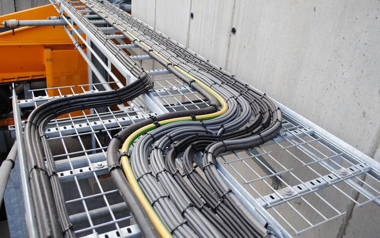
Dense Cable Trays: When multiple power cables are packed tightly together on a single horizontal or vertical cable tray, they experience mutual heating. Each cable acts as a small radiator, warming its neighbors. BS 7671 provides grouping correction factors ($C_{g}$) that must be combined with the temperature correction factors ($C_{a}$). In large industrial installations, the combined derating factor can drop below 0.50, meaning a cable can only be safely loaded to half of its nominal capacity unless physical spacing is increased.
Enclosed Ducts and Trenches: Cables pulled through underground plastic ducts or enclosed concrete trenches suffer from restricted natural air circulation. The air inside the duct becomes trapped, creating a localized greenhouse effect that raises the ambient temperature around the cable sheath and necessitates aggressive thermal derating.
Rooftop and Exposed Outdoor Runs: Cables routed across flat industrial roofs or along open structural steel pipe racks absorb direct thermal energy from solar radiation. In these scenarios, the effective ambient temperature can easily exceed 60°C, requiring the design team to either significantly increase the conductor cross-sectional area or provide protective solar shields to shade the cable routes.
6. UV Resistance for Outdoor Installations
A major challenge for outdoor electrical installations in Oman and the UAE is the extreme intensity of solar ultraviolet (UV) radiation. Industrial sites across the Gulf—such as the expansive oil refineries in Ruwais, the heavy industrial zones in Sohar, massive container berths in Jebel Ali, and open-pit aggregate mines in Fujairah—require extensive outdoor cable routing. Thousands of meters of low-voltage power, control, and sensitive instrumentation cables run along open structural steel pipe racks, elevated cable ladders, and exterior process structures, fully exposed to the elements.
This constant exposure to solar radiation presents a serious threat to the non-metallic components of a cable assembly. Standard formulation polymers, such as generic polyvinyl chloride (PVC) or standard polyethylene (PE) used for outer jackets, are highly susceptible to UV degradation, a process known as photo-oxidation.
The high-energy photons present in ultraviolet light break down the molecular polymer chains within the plastic jacket. Over time, this chemical degradation manifests as a visible fading of the sheath color, followed by surface micro-cracking, loss of flexibility, and eventual deep embrittlement. Once the outer sheath loses its structural integrity and begins to crack open, it creates a pathway for moisture, salt spray, atmospheric humidity, and industrial chemicals to penetrate into the inner layers of the cable.
To prevent premature degradation, it is critical to specify and utilize UV-resistant outer sheaths for all open-air installations, particularly on rooftops, material handling yards, coastal ports, and chemical process areas. Cable manufacturers achieve this specialized UV resilience by blending specific stabilizing additives into the outer jacket compound during the extrusion process. The most effective and widely utilized stabilizer is finely divided Carbon Black.
When added to the polymer matrix at a concentration of approximately 2% to 3%, Carbon Black absorbs the incoming ultraviolet photons and dissipates that energy harmlessly as low-level thermal energy, protecting the polymer bonds from breaking. For applications where a black outer jacket is undesirable due to visibility requirements—such as high-visibility safety jackets—advanced synthetic chemical stabilizers, known as Hindered Amine Light Stabilizers (HALS), are blended into the compound to provide equivalent long-term protection against photo-degradation.
Specifying UV resistance is not just an issue of keeping the cable looking good; it has a direct, profound impact on long-term operational safety and facility maintenance costs. When an outer sheath fails due to UV embrittlement, the entire underlying electrical circuit becomes vulnerable. Water ingress can cause immediate ground faults, short-circuits, and unexpected plant shutdowns that cost industrial operators thousands of dollars per hour in lost production.
Furthermore, replacing degraded cables in an operational, live process area is a difficult, time-consuming task that requires extensive labor, scaffolding, permit-to-work clearances, and specialized handling. By insisting on fully certified UV-stabilized jackets during the initial procurement and engineering design phases, project owners can protect their capital investment, ensure steady power delivery, and lower the total cost of ownership over the facility’s operating life.
7. Mechanical Protection
Industrial facilities in the Gulf region are high-impact, physically demanding environments. Heavy industrial operations—such as automated container ports, iron and steel foundries, massive mineral processing plants, and bulk material handling facilities—rely on large, moving machinery to process massive volumes of material.
In these settings, cables are subjected to significant physical forces. They must routinely withstand heavy impacts, abrasive friction, constant structural vibrations, and potential crushing forces from moving vehicles or shifting material loads. Consequently, selecting a cable based solely on its electrical capacity is insufficient; the cable’s physical construction must also be chosen to match the mechanical stresses of its environment.
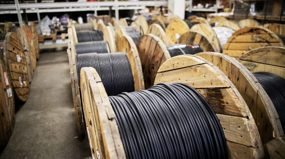
To ensure long-term reliability under these conditions, engineers must utilize heavy-duty cable designs that incorporate robust mechanical protection. The primary cable categories utilized to address these physical challenges include:
Armoured Cables: These cables feature an integrated layer of interlocking metal wire or tape wrapped around the inner bedding sheath, providing an exceptionally high level of resistance against crushing, impact puncture, and accidental mechanical damage.
Heavy-Duty Flexible Rubber Cables: Built using advanced elastomeric synthetic rubber compounds for both insulation and sheathing, these cables offer exceptional flexibility combined with high resistance to tearing, notch propagation, and abrasive wear.
Reinforced Industrial Cables: Designed with integrated internal double-jackets or high-tensile strength textile braids, these options are engineered to withstand continuous pulling and structural forces without experiencing geometric distortion.
Implementing these mechanically robust options is particularly critical in port facilities, mining operations, bulk aggregate handling plants, and heavy manufacturing zones. In a modern automated port, for example, massive ship-to-shore (STS) cranes travel rapidly along concrete rails while continuously hoisting multi-ton containers. The cables supplying power and control signals to these moving structures are constantly subjected to high acceleration forces, continuous bending, and friction against guide channels.
Similarly, in open-cast mineral mines in Oman, cables are dragged across sharp, unyielding limestone and rock surfaces. Using standard unarmoured or light-duty commercial cables in these applications would lead to rapid mechanical failure, resulting in frequent operational disruptions and safety hazards.
7.1 Where Armoured Cable Fits
Selecting the right type of mechanical protection requires a clear understanding of the operational motion profile of the connected equipment. The first major category is fixed installations—where the cable is installed once along a permanent route and is not intended to move during its operational life. For fixed routes where the risk of mechanical impact or crushing is moderate to high—such as cables laid in open concrete trenches, routed along low-level structural pipe racks, or buried directly in the ground—armoured cable is the industry standard.
Under British and international standards, this typically means specifying Steel Wire Armoured (SWA) cables for multi-core configurations, or Aluminium Wire Armoured (AWA) cables for single-core configurations to prevent magnetic hysteresis heating. The heavy metallic armor layer serves as a tough physical shield that deflects impacts from dropped tools, resists puncture from heavy equipment, and provides an excellent low-impedance path for earth fault currents.
The second major category involves dynamic installations—where the connected machinery undergoes continuous or repeated movement, trailing, or reeling as part of its daily operational cycle. In these applications, armoured cable cannot be used because steel wire armor is rigid; repeatedly bending an SWA cable will cause the internal metal wires to displace, bird-cage, and puncture inward, destroying the internal copper conductors.
For these dynamic settings, heavy-duty flexible rubber cables (such as NSSHÖU or NSHTÖU designs) must be specified. These cables utilize fine-stranded Class 5 or Class 6 flexible copper cores combined with tough, elastomeric rubber jackets. This construction allows the cable to bend repeatedly over small radii and withstand continuous reeling onto motorized drums while resisting surface abrasion from contact with concrete ground structures.
Finally, when the anticipated physical risk in an industrial facility is exceptionally high, engineers should not rely on the cable sheath alone for protection. In high-risk zones—such as low-clearance vehicle pathways, heavy material drop areas, or areas exposed to high temperatures near furnaces—design teams must implement additional mechanical containment systems. This involves routing cables through heavy-gauge galvanized steel conduits, enclosing them in structural steel trunking runs, or utilizing dedicated, fully enclosed cable tray management systems with protective peak covers. This multi-layered approach ensures the internal electrical network remains fully insulated from external physical impacts.
8. Fire Safety and LSZH
In modern industrial and commercial project design across the Middle East, fire safety has become a primary driver of technical specifications. Historically, industrial facilities relied heavily on cables jacketed with standard Polyvinyl Chloride (PVC). While PVC offers good electrical insulation, affordability, and reasonable oil resistance, it presents serious hazards during a fire.
When standard PVC is subjected to the high temperatures of an electrical fire, it undergoes thermal decomposition and releases thick, black smoke along with highly toxic, corrosive Hydrogen Chloride (HCl) gas. In enclosed environments, this dense smoke rapidly obscures visibility, blocking escape routes and hindering emergency response efforts. Furthermore, when the released HCl gas mixes with atmospheric moisture or the water vapor from fire sprinkler systems, it forms hydrochloric acid. This acid deposits onto sensitive electronic components, control systems, and instrumentation racks across the facility, causing widespread corrosion and destroying expensive equipment that may not have been touched by the actual flames.
To mitigate these risks, Low Smoke Zero Halogen (LSZH)—also referred to as Halogen-Free Flame Retardant (HFFR)—cables are widely preferred and frequently mandated across the Middle East. LSZH cables are engineered using specialized thermoplastic or thermoset compounds that contain high concentrations of inorganic mineral fillers, such as Aluminum Trihydrate (ATH) or Magnesium Hydroxide (MDH).
When exposed to flame, these mineral fillers undergo an endothermic chemical reaction, releasing chemically bound water molecules that cool the fire front and suppress smoke generation. The resulting exhaust consists primarily of non-toxic water vapor and carbon dioxide, producing zero halogen gases. This significantly improves visibility and ensures the atmosphere remains non-corrosive, protecting both human life and critical electronic infrastructure.
The specification of LSZH systems becomes critical in specific zones of an industrial plant, including:
Enclosed Plant Rooms and Substation Basements: Spaces where dense cable configurations are installed, and natural ventilation is highly restricted.
Control Buildings and SCADA Rooms: Hubs containing the sensitive microelectronics, servers, and control systems needed to safely monitor and operate the industrial facility.
Tunnels and Underground Access Shafts: Enclosed personnel pathways where smoke accumulation poses an immediate risk of asphyxiation.
Designated Escape Routes and Common Stairwells: Pathways that must remain clear of toxic smoke and maintain high visibility to facilitate rapid evacuation.
High-Occupancy Administrative Spaces: Areas within the industrial complex where administrative staff are concentrated.
When designing a comprehensive fire safety strategy, engineers must evaluate both the probability of a fire occurring and the consequences of smoke generation during an evacuation. This requires looking closely at the fire performance certifications of the cable assets. Under BS 7671 and international IEC frameworks, cables are subjected to rigorous tests to verify their performance.
Designers must ensure that specified LSZH cables comply with IEC 60332-1-2 and IEC 60332-3-24 to verify flame retardancy and resistance to vertical flame spread. Furthermore, cables must meet IEC 61034-2 standards to confirm a minimum smoke light transmittance value (typically greater than 60%), and comply with IEC 60754-1 and IEC 60754-2 to verify that the amount of halogen acid gas evolved is negligible, maintaining a safe pH value above 4.3. This rigorous testing approach ensures that the cable system will support, rather than hinder, emergency response efforts during a fire.
9. Cable Selection by Environment
A successful, high-performance electrical design requires that the selected cable construction matches the specific micro-environment of its installation route, rather than relying on a single, uniform cable type across the entire project. An industrial plant in the UAE or Oman contains many distinct zones, each presenting a different combination of thermal, chemical, mechanical, and fire hazards.
A common engineering mistake is to size a circuit based purely on its electrical load and then use the same cable construction from the main substation all the way to the field instrument, regardless of the environments it crosses. This approach often leads to either over-engineering in low-risk zones or dangerous under-specification in high-risk areas.
To illustrate how cable selection must adapt to different micro-environments within a single facility, consider the following standard industrial zones:
9.1 Indoor Plant Areas
Inside climate-controlled substation rooms, motor control centers (MCCs), and air-conditioned administrative spaces, environmental stresses are minimal. The ambient temperature is maintained at a stable 21°C to 25°C, and there is no risk of UV exposure or standing water. In these lower-occupancy, low-risk indoor zones, standard XLPE-insulated power cables with standard outer sheaths are perfectly acceptable and cost-effective. However, if these cables enter an unventilated basement cable vault where dense grouping occurs, fire performance and grouping derating factors must still be assessed.
9.2 Outdoor Exposed Infrastructure
Once cable routes leave the protection of indoor plant rooms and venture onto open outdoor structures, the selection criteria must change immediately. For an outdoor installation in the UAE or Oman, cables must feature a robust, UV-stabilized outer jacket (such as carbon-black loaded compounds) to withstand intense solar radiation. The design team must also apply temperature correction factors based on a realistic ambient baseline of 45°C to 50°C, and include solar radiation adjustments if the trays are exposed to direct sunlight.
9.3 Heavy Mechanical and Process Zones
In heavy processing areas—such as the under-screen areas of aggregate plants, slag handling yards in steel mills, or mobile conveyor links in mining sectors—mechanical stress is the dominant hazard. In these zones, standard cables will quickly fail due to physical impacts and abrasion.
Engineers must specify robust armoured constructions for fixed routes, or heavy-duty armoured rubber cables for areas subject to movement. The outer jacketing materials must be chosen for high tear resistance and oil resilience, ensuring they can withstand exposure to industrial lubricants and mechanical impacts without tearing open.
9.4 Emergency and Safety-Critical Circuits
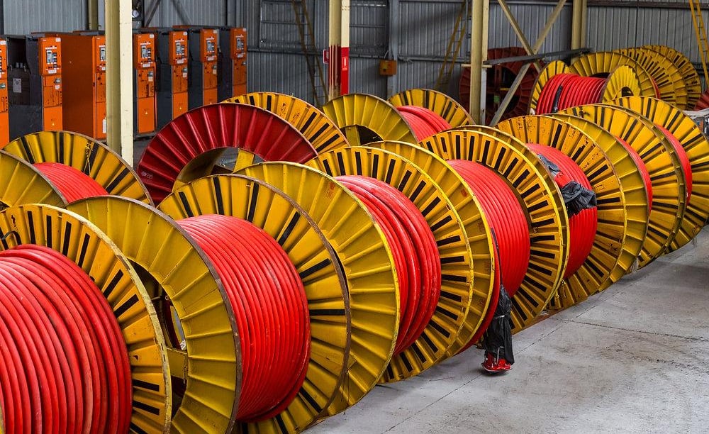
For circuits that must remain operational during an emergency—such as fire pumps, emergency lighting networks, toxic gas detection systems, and motorized isolation valves—the selection criteria focus heavily on fire survival. These circuits require dedicated fire-resistant cables, often featuring a mica tape wrap around the copper conductor or a complete Mineral Insulated Copper Cable (MICC) construction.
These cables are engineered to survive temperatures exceeding 950°C for up to 3 hours under mechanical shock and water spray conditions (complying with BS 6387 Category CWZ or IEC 60331 standards). This ensures that critical safety control loops remain active during a fire, allowing for a structured, safe shutdown of the plant.
10. Industrial Sectors in Oman and UAE
The practical application of these cable selection rules and BS 7671 engineering adaptations varies across different industrial sectors in the Gulf region. Each major industry presents a unique combination of operating demands and environmental hazards, requiring tailored solutions to ensure long-term reliability.
10.1 Oil and Gas Projects
The oil, gas, and petrochemical sectors form a major component of the economic infrastructure in Oman and the UAE. Facilities such as downstream refineries, upstream gas processing plants, and crude storage terminals operate continuously and require exceptionally high levels of reliability.
In these environments, cables must feature high heat tolerance to withstand both the ambient desert climate and the high process temperatures near piping networks. Furthermore, because these sites handle volatile hydrocarbons, cables must be highly resistant to chemical attack, including exposure to aliphatic and aromatic hydrocarbons, solvents, and crude oils. This requires specifying specialized lead-sheathed cables or advanced nylon-barrier multilayer jackets that prevent chemical vapors from penetrating the insulation. Fire safety is also critical, requiring extensive use of LSZH materials and fire-resistant control loops to manage emergency shutdown systems safely.
10.2 Ports and Cranes
The strategic geographic locations of the UAE and Oman have driven the development of massive maritime hubs, including Jebel Ali Port in Dubai, the Port of Khalifa in Abu Dhabi, and the strategic industrial ports of Sohar and Duqm in Oman. These facilities rely on large fleets of Ship-to-Shore (STS) container cranes, Rail-Mounted Gantry (RMG) systems, and bulk shippers.
The electrical systems powering this heavy material handling equipment require high mechanical strength, excellent UV resistance, and flexible industrial cable designs. Power cables feeding moving crane structures must handle continuous reeling and unreeling from motorized drums, high acceleration forces, and ongoing exposure to saline coastal humidity and UV radiation. This demands specialized flexible trailing rubber cables with integrated anti-torsion braids to prevent structural twisting and failure during high-speed operations.
10.3 Mining and Aggregate Operations
In the mountain ranges of Oman (such as the Al Hajar region) and the emirate of Fujairah, large-scale mining and quarrying operations extract minerals, limestone, and aggregate materials for global construction markets. The machinery used in these sectors—including primary crushers, mobile screening rigs, heavy excavators, and overland conveyor networks—operates under rough conditions.
Cables in these environments face extreme physical abuse, including continuous abrasion from sharp rock surfaces, heavy vibrations from crushing machinery, and high impact risks from falling stones. Procurement teams in this sector must prioritize exceptional abrasion resistance and structural durability. This requires specifying heavy-duty rubber-sheathed cables (such as NSSHÖU standard lines) that can be dragged over jagged rock surfaces and operate reliably when submerged in abrasive mud and dewatering pits.
10.4 Desalination Plants
Due to limited natural freshwater resources, the UAE and Oman rely heavily on large-scale seawater desalination facilities, including Independent Water and Power Plants (IWPPs) operating along the coast. These facilities combine several demanding environmental challenges, including outdoor solar exposure, high ambient humidity, and continuous exposure to corrosive seawater, chlorine, and chemical water-treatment agents.
Cables powering heavy intake pumps, chemical dosing systems, and high-pressure reverse osmosis filtration racks must feature robust, chemical-resistant, and watertight construction. A failure in a primary power feeder line at a desalination facility can disrupt water supplies to municipal networks, making detailed cable specification and material validation a critical priority for regional engineers.
11. Practical Specification Logic
To consistently deliver safe, compliant, and cost-effective electrical distribution networks across Middle Eastern industrial projects, engineering teams should follow a structured, step-by-step practical specification logic. Rather than selecting components based on intuition or legacy specifications, designers should utilize a clear, sequential decision tree that integrates the principles of BS 7671 with the realities of the local Gulf environment.
[ Step 1: Thermal Baseline ] Determine Max Ambient (Air: 45-50°C, Soil: 35°C) & Grouping Configuration
│
▼
[ Step 2: Mechanical Profile ] Identify Motion State: Fixed Installation vs. Dynamic (Reeling/Trailing)
│
▼
[ Step 3: Environmental Protection ] Evaluate UV Exposure & Chemical Ingress Risks (Specify Stabilized Jackets)
│
▼
[ Step 4: Life Safety Integration ] Assess Containment Space Occupancy (Select LSZH vs. Fire-Resistant Systems)
│
▼
[ Step 5: Final Sizing Derating ] Apply Correction Factors: Design Current (Ib) ≤ Rated Current (Iz) after Derating
Step 1: Establish the Thermodynamic Baseline
The cable sizing process must begin by determining the actual site conditions. The engineering team must identify the maximum ambient air temperature along the entire cable route (typically 45°C to 50°C for outdoor areas in the Gulf) or the maximum ground temperature (typically 35°C for buried installations).
Next, the installation method must be clearly defined according to BS 7671 framework classifications—whether the cables will be laid on open ladders, enclosed in perforated trays, or pulled through buried conduits. Finally, the grouping configuration must be evaluated by counting the number of adjacent circuits sharing the same containment space to account for mutual heating.
Step 2: Determine the Mechanical Motion Profile
Engineers must evaluate the physical movement requirements of the connected electrical load. If the machinery is entirely stationary—such as a fixed transformer, a localized distribution panel, or a permanent pump station—the design should prioritize rigid, highly protective systems, typically specifying Steel Wire Armoured (SWA) or Aluminium Wire Armoured (AWA) cables.
Conversely, if the load involves moving machinery—such as a traveling crane hoist, a tripper conveyor, or a mobile processing rig—the design must shift to high-flexibility, heavy-duty elastomeric rubber cables equipped with appropriate anti-torsion features to manage dynamic forces.
Step 3: Evaluate Environmental and Chemical Hazards
The entire cable route must be reviewed for outdoor exposure and environmental hazards. If any portion of the run is exposed to direct sunlight, the specification must require a fully certified UV-resistant outer jacket stabilized with Carbon Black or an equivalent HALS additive.
Additionally, the surrounding area must be screened for chemical risks, such as proximity to hydrocarbon storage tanks, salt spray in coastal zones, or chemical dosing lines in desalination facilities. If chemical exposure is likely, the engineer must specify appropriate protective barriers, such as lead sheaths, nylon layers, or specialized fluoro-elastomeric jackets.
Step 4: Integrate Fire Safety and Life Safety Requirements
The human occupancy and evacuation characteristics of the installation area must be clearly defined. If the cable is located inside an enclosed plant room, a control center, an underground tunnel, or along a designated emergency escape route, standard PVC materials must be rejected.
The engineer must specify Low Smoke Zero Halogen (LSZH) compounds that comply with international certifications for flame retardancy, low smoke density, and zero halogen evolution. For circuits critical to plant safety during an emergency, the specification must require certified fire-resistant cables capable of surviving direct fire exposure.
Step 5: Execute Final Cable Sizing and Derating Verification
A fundamental principle of robust design is that cable sizing must be verified after applying all necessary derating factors, never before. The design engineer must calculate the total effective current-carrying capacity ($I_{z}$) by multiplying the base catalog rating ($I_{t}$) by all relevant correction factors for temperature ($C_{a}$), grouping ($C_{g}$), and solar exposure.
The resulting derated capacity must be greater than or equal to the design current of the circuit ($I_{b}$). Finally, the engineer must check that the selected conductor cross-section meets acceptable voltage drop limits over long distances and can safely handle maximum anticipated short-circuit fault currents without thermal failure.
By following this systematic workflow, engineering teams can ensure that the final cable specification is based on the actual physical stresses of the site, rather than idealized catalog assumptions. This approach eliminates guesswork, protects capital infrastructure, and guarantees that the electrical network will remain safe and operational throughout its intended service life.
12. Conclusion
Applying international standards across different geographic regions requires careful adaptation to local conditions. As demonstrated throughout this comprehensive guide, BS 7671 (the IET Wiring Regulations) provides an exceptionally reliable framework for the design, sizing, and execution of electrical installations. However, when importing this British framework into the industrial landscape of the Sultanate of Oman and the United Arab Emirates, it cannot be applied blindly. The physical realities of the Gulf environment require engineers to adapt theoretical design models to meet actual site conditions.
Designing reliable electrical infrastructure for the Middle East requires balancing multiple interconnected environmental factors:
Temperature Derating: The high ambient temperatures of the Gulf require systematic derating calculations to protect cable insulation from thermal failure.
UV Resistance: High solar radiation levels require the use of certified UV-stabilized outer jackets to prevent premature cracking and degradation.
Mechanical Protection: Heavy industrial zones demand robust mechanical protection, requiring SWA cables for fixed installations and flexible rubber cables for dynamic applications.
Fire Safety: Enclosed spaces and critical control loops necessitate high-performance LSZH and fire-resistant cable materials to safeguard personnel and assets.
Ultimately, successful engineering projects in the Middle East require a more conservative, environment-specific approach than standard installations in temperate climates. Design teams, EPC contractors, and procurement managers must look beyond standard factory specifications and catalog assumptions.
By grounding every cable selection decision in the actual physical stresses, thermal gradients, and mechanical forces the cable will face in the field, engineers can build resilient, high-performance electrical networks. This approach ensures long-term operational continuity, supports regional industrial growth, and maintains high standards of safety and reliability across the Gulf.
Port crane cables | Mining cables | Reeling cables | Trailing cables | Festoon cables | Heavy-duty power cables | Medium voltage cables | Offshore crane cables | Underground mining cables | Dragline cables | Shearer cables | Container handling cables | STS crane cables | RTG cables | Mobile equipment cables | Armored cables | Flexible power cables | VFD cables | Submersible cables | Cold resistant cables | Abrasion resistant cables | Flame retardant cables | Marine environment cables | Opencast mining | Underground operations
© 2006 All rights reserved.
[INDUSTRIAL_CABLES]
INDUSTRIAL GRADE CABLE SYSTEMS | PORT & MINING SOLUTIONS
TEL: +86 153 7530 2641 |MAIL: hongjing.Wang@feichuncables.com