
Choosing the Right Power Cable for Port Cranes in the Middle East: A Technical Guide
Discover how to select optimal power cables for port crane operations in extreme Middle East environments. Compare reeling vs. marine cables with real-world port case studies and technical specifications.
hongjing.Wang@Feichun
4/28/202622 min read
Introduction
Port cranes are the backbone of modern shipping operations. Whether moving containers at lightning speed or handling bulk cargo, these machines demand absolute reliability from their electrical systems. Yet in the Middle East, where temperatures soar above 50°C and sandy coastal conditions accelerate cable degradation, selecting the wrong cable can lead to catastrophic downtime and safety hazards.
The challenge isn't complexity—it's specificity. A cable perfect for an automated container terminal in Dubai's stable climate may fail within months at an open-air bulk handling facility in Saudi Arabia. Environmental stress, operational demands, and installation methods each create unique cable requirements that standard specifications often overlook.
This guide cuts through the technical jargon to help you understand why cable selection matters, what sets different cable types apart, and how to match your port infrastructure to the cables that will keep it running reliably for decades.
The Middle East Port Environment: Why Standard Cables Fail
The Middle East presents one of the world's most demanding operating environments for electrical infrastructure. Understanding these specific stressors is crucial before selecting any cable system.
Temperature Extremes Beyond Design Limits
Middle Eastern ports experience ambient temperatures regularly exceeding 50°C during operational hours. Some inland facilities near industrial zones report sustained temperatures above 55°C. Most standard industrial cables are rated for 40°C to 45°C ambient conditions—a design margin that evaporates in Middle Eastern summer months.
When cables operate above their rated temperature, insulation materials begin to experience accelerated degradation. Ethylene Propylene Rubber (EPR), commonly used in power cables, shows measurable loss of mechanical properties at every 10°C increase above its thermal rating. This means a cable rated for 45°C ambient operating at 55°C will age roughly twice as fast as under standard conditions.
UV and Oxidative Degradation from Unfiltered Sunlight
The Middle East receives among the world's highest solar irradiance levels. Port cranes operate in open-air environments with no shade structures, exposing cable sheaths to 8-12 hours of direct sunlight daily. Unlike temperate climates where winter provides seasonal relief, Arabian coastal areas experience year-round intense UV exposure.
Polymeric cable materials breakdown when exposed to UV radiation. Without proper protection compounds, sheath materials become brittle and crack—initiating points for moisture ingress and eventual conductor failure.
Sand and Dust Abrasion
Persistent wind in many Middle Eastern ports generates sandstorms that can last hours. Fine sand particles, when combined with moisture from coastal spray, create an abrasive slurry that attacks cable jackets. Dynamic cable systems—those constantly moving through reeling drums or festoon tracks—experience the worst damage, as the continuous flexing action works sand particles into micro-cracks in the jacket.
Chemical Exposure and Corrosion
Most Middle Eastern ports sit at the interface between industrial zones and coastal environments. Cables are simultaneously exposed to:
Salt spray from seawater (chloride corrosion)
Petrochemical residues from refineries and oil terminals
Sulfur compounds from fuel handling operations
Alkaline dust from cement and mineral handling facilities
These chemical environments accelerate metal corrosion and can penetrate standard rubber jackets, attacking copper conductors and reinforcement braids.
Continuous Mechanical Stress
Port cranes operate nearly 24/7 during peak seasons. Unlike intermittently-used industrial equipment, these machines create relentless mechanical stress on power cables through continuous bending, tensioning, and acceleration forces. An automated container crane might complete 30-40 cycles per hour, subjecting power cables to tens of thousands of stress cycles annually.
Cable Movement Types: Understanding Dynamic vs. Static Applications
Before comparing specific cable models, it's essential to understand how different port crane systems deliver power to their load, because this fundamentally determines which cables will survive.
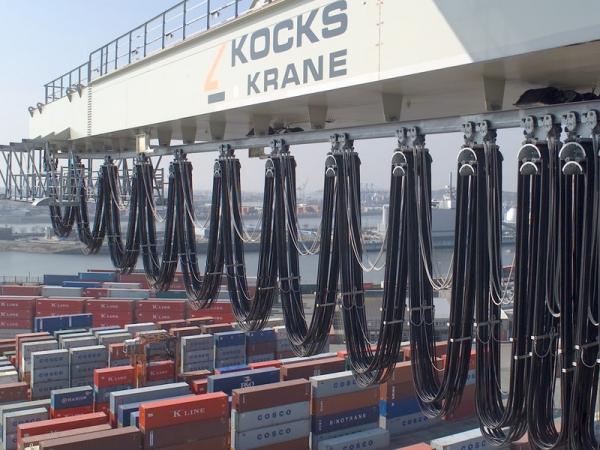
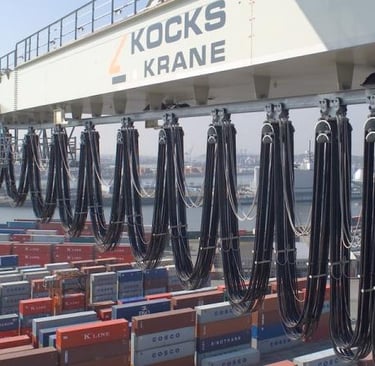
Reeling Cable Systems: The High-Stress Choice
Reeling systems use large drums that wind and unwind cables as cranes move. This approach powers most ship-to-shore cranes and container handling equipment. The cable is continuously flexed, twisted, and subjected to dynamic tensile loads as the crane accelerates and decelerates.
In reeling systems, the cable experiences:
Dynamic bending with radius changing from 1 meter to 20+ meters repeatedly
Torsional stress as the drum rotates (up to ±25°/meter)
Tensile forces ranging from static load to dynamic shock loads during emergency stops
High travel speeds (up to 240+ m/min on modern cranes)
This is the most demanding electrical cable application. The insulation and jacket must flex millions of times without cracking, while maintaining electrical integrity.
Festoon Cable Systems: Moderate Stress
Festoon systems guide cables through C-shaped tracks running parallel to the crane's travel path. The cable bends over rollers at regular intervals but doesn't twist or experience the severe tensile shocks of reeling systems.
This approach appears in lighter-duty gantry cranes and some bulk handling systems where load capacity is moderate (typically under 50 tons).
Fixed Installation: Static Requirements
Some port cranes use permanently installed cable trays and conduit systems. While mechanically simpler than dynamic systems, coastal environment exposure remains demanding. These applications prioritize corrosion resistance and weather protection over flexibility.
Real-World Middle East Port Case Studies: Where Selection Determines Reliability
Case Study 1: Automated Container Terminal, Dubai Jebel Ali Port
The Jebel Ali Port operates one of the world's most advanced automated container terminal (ACT) systems. Rubber-tyred gantry cranes (RTGs) equipped with automated positioning systems move containers across yard stacks up to 5 containers high.
Each RTG uses a reeling cable system with three separate 95mm² power cables supplying 3-phase power to drive motors. The system operates continuously from 6:00 AM to 11:00 PM daily, completing approximately 35 cycles per hour.
Environmental challenges at this site include:
Ambient temperatures reaching 54°C during summer
Coastal salt spray from the Persian Gulf
High UV exposure with no shade structures
Fine dust from bulk cargo operations at adjacent terminals
The facility initially specified standard 0.6/1kV industrial reeling cables. Within 18 months, failure rates exceeded 2 cables per year per crane (total fleet: 40 cranes = unacceptable downtime frequency). Root cause analysis revealed:
Insulation cracking at bending points due to thermal aging
Jacket degradation exposing semiconductive layers
Corrosion of tinned copper braiding reducing mechanical strength
Salt deposits accelerating moisture penetration
After switching to specialized medium-voltage reeling cables with enhanced thermal ratings and improved jacket compounds, failures dropped to approximately 0.3 cables per year fleet-wide. The cable cost premium (roughly 35%) was recouped within 2 years through reduced downtime and maintenance.
Case Study 2: Bulk Cargo Port, Jubail Industrial Zone, Saudi Arabia
Jubail hosts one of the world's largest industrial ports, handling dry bulk commodities (grain, fertilizer, minerals) and petrochemical products. The facility operates large ship loaders and unloaders—machines that can position booms up to 60 meters from the vessel, extending and retracting throughout the loading process.
Ship loaders use rope-driven reeling systems where power cables travel from the control cabin to motors located at the boom tip and base. This creates a unique challenge: cables must route through the rope guides and pulleys, experiencing small radius bends (as tight as 200mm on some designs) combined with high tensile loads (up to 25 tonnes pulling force during emergency stops).
The ambient temperature at Jubail frequently exceeds 52°C, and the industrial atmosphere contains sulfurous compounds from nearby refineries. Standard power cables showed premature failure within 12-24 months, with failure modes including:
Insulation puncture from sharp bend-radius transitions
Jacket embrittlement from combined heat and chemical exposure
Conductor strand breakage under dynamic tensile loads
Water intrusion leading to short circuits
The site switched to cables specifically engineered for dynamic tensile applications with:
Reinforced insulation compounds resisting chemical attack
High-flexibility conductor designs handling micro-radius bends
Jacket materials rated for continuous 90°C conductor temperature
Mechanical reinforcement limiting conductor movement
Cable life extended to 4-5 years with this specification, and more importantly, failure modes shifted from sudden electrical faults to gradual degradation (allowing preventive maintenance).
Case Study 3: Oil Terminal Crane, Ras Al Khaimah
A specialized offshore terminal handling crude oil import/export operations uses fixed-mount cranes with manifold arms that remain installed year-round. Unlike mobile cranes, these systems don't experience bending stress, but they face intense chemical corrosion and UV exposure.
Power cables run along structural frameworks, exposed to:
Continuous salt spray
Oil mist during loading/unloading operations
Thermal cycling from 20°C at night to 58°C during peak daytime
Ozone generation from electrical equipment (motors, switches, breakers)
Initial cable installations using standard 0.6/1kV industrial cables showed sheath degradation within 8-14 months. UV exposure turned black jackets gray, and physical testing revealed 40% reduction in tensile strength. Salt deposits penetrated the jacket, reaching reinforcement braiding and initiating corrosion.
Switching to marine-rated cables with enhanced UV resistance, oil-resistant compounds, and robust sheath systems extended cable life to 6-8 years. The marine-rated cables incorporated halogen-free compounds meeting both environmental regulations and intrinsic safety standards for oil terminal operations.
Comparing Reeling Cables vs. Marine Cables: Technical Specifications and Applications
Understanding the fundamental differences between these cable families is essential for correct selection. While both serve critical functions in port operations, they excel under different conditions.
Reeling Cable Specifications and Engineering Design
Reeling cables are specifically engineered for continuous dynamic flexing, high tensile stress, and mechanical shock loads. These are the workhorses of ship-to-shore cranes, RTG systems, and mobile port equipment.
Electrical Characteristics:
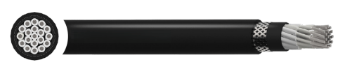
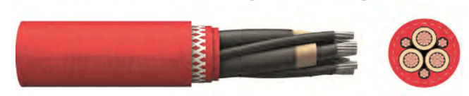
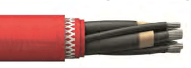
Medium-voltage reeling cables for port applications typically carry ratings of 1.8/3 kV to 12/20 kV, with three-core designs for 3-phase power distribution. The conductor is made from electrolytic copper tinned to prevent oxidation, then stranded into very flexible configurations (class FS stranding) allowing bend radii of 20-30× the cable diameter.
Mechanical Engineering:
The insulation material in advanced reeling cables uses high-grade EPR compounds with improved mechanical properties compared to standard EPR. The addition of reinforcing particles and sophisticated cross-linking chemistry maintains elasticity even after thermal aging.
The sheath system uses a sandwich construction: an inner EPR layer provides water resistance, a reinforced polyester braid provides torsional strength and prevents jacket rotation, and an abrasion-resistant outer sheath (typically PCP-based material) withstands sand and UV exposure.
Conductor Design for Dynamic Stress:
A critical engineering feature often overlooked is the semiconductive layer system. Reeling cables use inner and outer semiconductive layers (typically EPR and modified NBR) designed to strip cleanly when cold—enabling field terminations under Middle Eastern conditions. More importantly, the outer semiconductive layer reduces stress concentrations at the insulation surface, allowing the cable to bend repeatedly without insulation cracking.
Temperature Ratings:
Premium reeling cables for Middle Eastern deployment are rated for 90°C continuous conductor temperature, with maximum permissible operating voltages slightly above their basic rating. This thermal margin is critical in applications where cable temperature regularly reaches 85-88°C due to I²R heating in the copper conductors.
Mechanical Limits:
Reeling cables specify maximum tensile loads (typically 20-30 N/mm² for the conductor) and permissible torsional stress (±25°/meter or greater). These engineering limits define the safe operational envelope—exceeding them initiates rapid degradation.
A typical 3×95mm² reeling cable for 12/20 kV service can handle:
Permissible tensile force: 5,700 Newtons (approximately 580 kilograms pulling force)
Dynamic tensile force during acceleration: 8,550 Newtons
Outer diameter: approximately 51 millimeters
Weight: approximately 7,570 kg/km
Current carrying capacity: approximately 301 Amperes (at 30°C ambient, surface mounting)
Thermal Aging Resistance:
Advanced reeling cables incorporate antioxidants and thermal stabilizers in the EPR insulation, allowing them to maintain mechanical properties after thousands of hours at elevated temperatures. The outer sheath uses UV absorbers and antiozonants to resist atmospheric degradation.
Marine Cable Specifications and Engineering Design
Marine cables serve a fundamentally different purpose: stationary or slowly-moving installations in harsh chemical environments. They prioritize corrosion resistance, weather protection, and long-term environmental stability over flexibility and dynamic stress handling.
Electrical Characteristics:
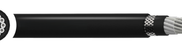
Marine power cables typically operate at 0.6/1 kV, with single-core or multi-core designs. The voltage rating reflects their typical use in ship's systems and fixed electrical infrastructure, where dynamic voltage swings are minimal.
Material Selection for Corrosion Resistance:
The defining feature of marine cables is their material selection. Conductors use tinned copper (not bare copper), where a thin layer of tin prevents direct copper-seawater contact. The tin coating also improves solderability for terminations in marine environments.
Insulation uses halogen-free EPR compounds that, even when degraded, release only water vapor and carbon dioxide rather than toxic chlorine or fluorine gases. This is critical because marine cables are often installed near human workspaces and in confined engine rooms.
The sheath typically uses halogen-free compounds with enhanced oil resistance, meaning the jacket itself resists penetration by petroleum products and chemical vapors.
Environmental Protection Features:
Marine cables incorporate a color-coded identification system (often with black semiconductive layers visible under UV light during factory inspection), enabling rapid identification in complex ship and port installations.
The braid reinforcement uses tinned copper wire rather than standard steel, preventing galvanic corrosion between the braid and the copper conductor. In salt-water environments, standard steel braiding can corrode and lose up to 80% of tensile strength within 2-3 years.
Flame Retardance and Safety:
Marine cables are rigorously tested for flame propagation (IEC 60332-3-24: fire survival test). Halogen-free compounds naturally provide this property by releasing water that cools the insulation, preventing flame spread.
Mechanical Design:
While marine cables aren't designed for tight bending, they maintain flexibility for installation routing. The minimum bending radius is typically 8× the cable diameter—significantly larger than reeling cables (20-30×) but reasonable for fixed installations.
A typical 3×50mm² marine cable for 0.6/1 kV service provides:
Outer diameter: approximately 18 millimeters
Weight: approximately 1,840 kg/km
Current carrying capacity: approximately 137 Amperes (at 45°C ambient in air)
Tensile strength: rated for static load only, not dynamic cycling
Chemical Resistance Matrix:
Marine cable jacketing resists:
Saltwater and seawater spray
Mineral oils and petroleum fuels
Ozone from air discharge equipment
UV radiation and sunlight
Moisture and fungal growth
The key difference from standard industrial cables is the engineered compound formulation, not simply thickness. A thicker standard industrial cable jacket will still degrade in salt spray; a properly formulated marine jacket of normal thickness will resist for decades.
Critical Differences in Real-World Performance
The performance gaps between reeling and marine cables become stark in field conditions:
Flexibility Test: A reeling cable bent to 200mm radius 10,000 times shows no insulation cracks. The same marine cable bent to the same radius shows multiple insulation punctures after 2,000 cycles.
Salt-Spray Exposure: A marine cable exposed to salt spray for 2,000 hours shows no visual jacket degradation. A reeling cable shows jacket surface crazing and visible braid corrosion under the same conditions.
Thermal Aging: After 2,000 hours at 90°C, a reeling cable retains approximately 85% of its original tensile strength. A standard industrial cable (without thermal stabilizers) retains only 60%.
These performance deltas explain why selecting the wrong cable type leads to rapid failure, not gradual degradation.
Google Featured Snippet: Quick Answer
When should you use reeling cables vs. marine cables at Middle Eastern ports?
Use reeling cables for dynamic applications with continuous movement: ship-to-shore cranes, rubber-tyred gantries, ship loaders, and any system that winds power cables on rotating drums. These cables handle repeated bending, twisting, and high tensile stress. Use marine cables for fixed installations in harsh coastal environments: permanent crane infrastructure, oil terminal manifolds, and stationary electrical distribution systems. Marine cables excel at resisting salt spray, oil exposure, and UV degradation but cannot withstand continuous flexing. In the Middle East specifically, both cable types should feature enhanced thermal ratings (90°C minimum conductor temperature) and improved UV/chemical resistance compounds to survive ambient temperatures exceeding 50°C and intense solar exposure.
AI Search Optimization: FAQ Module
Q1: What cable temperature rating do I need for Middle Eastern port operations?
A: Minimum 90°C conductor temperature rating is recommended. While standard industrial cables are rated for 70°C or 80°C, Middle Eastern ports regularly experience sustained ambient temperatures of 50-55°C, combined with I²R heating in conductors carrying peak loads. This pushes cable temperature to 85-90°C under normal conditions. Using cables rated for only 70°C ambient results in conductor temperatures exceeding their thermal limit, accelerating insulation degradation and shortening cable life from 5-7 years to 2-3 years. The cost difference for 90°C-rated cables is typically 8-15%, easily justified by extended service life.
Q2: Why do port cables fail faster in the Middle East than in Europe or North America?
A: Four factors compound to accelerate failure: (1) ambient temperature averaging 10-15°C higher than standard design conditions, (2) year-round UV exposure compared to seasonal variation in temperate climates, (3) salt spray and chemical corrosion from coastal and industrial environments, and (4) continuous operation schedules (often 20+ hours daily) compared to intermittent industrial duty. Combined, these conditions can reduce cable lifespan by 50-70% compared to standard climate deployments.
Q3: Can I use lower-cost standard cables and replace them more frequently?
A: This strategy often backfires economically and operationally. While a standard cable might cost 40% less, its failure results in crane downtime costing $15,000-$50,000 daily depending on cargo volume and port penalties. One unplanned failure pays for a premium cable inventory. Additionally, frequent replacements create compound downtime from installation and testing delays. Properly selected cables matching the application environment minimize total cost of ownership by eliminating emergency replacements.
Q4: What's the difference between "marine-grade" and "port-grade" cables?
A: These terms lack formal standardization. "Marine-grade" typically means IEC 60092-compliant cables with halogen-free insulation meeting ship system requirements. "Port-grade" is marketing terminology suggesting environmental durability without specific standards. Always specify cables by voltage, application (reeling vs. fixed), conductor material, and relevant standards (IEC 60811, DIN VDE 0250, etc.) rather than relying on grade terminology.
Q5: How do I know if my crane cable is near end-of-life?
A: Five warning signs indicate replacement planning is needed: (1) visual crazing or micro-cracks in the jacket, (2) semiconductive layer flaking during handling, (3) discoloration of the sheath from UV exposure, (4) difficulty in bending to normal bend radius (stiffness indicates insulation degradation), (5) any evidence of moisture on the conductor during termination inspection. Once any of these appear, plan replacement within 3-6 months rather than waiting for failure.
Q6: Does cable diameter affect performance in Middle Eastern conditions?
A: Yes, critically. Larger diameter cables (e.g., 95mm² vs. 50mm²) experience lower current density in the conductor, resulting in lower I²R heating and lower operating temperature. A 95mm² cable carrying 250 Amperes might operate at 80°C; the same current in a 50mm² cable would reach 110°C. In Middle Eastern ambient temperatures of 50°C+, this temperature margin determines whether the cable survives within its thermal rating or exceeds it. When sizing cables for these environments, use the next larger cross-section compared to temperate climate calculations.
Q7: What maintenance prevents cable failure?
A: Quarterly inspections identifying early degradation signs allow preventive replacement. Visual inspection of jacket condition, flex testing at bending points, and thermography imaging of loaded cables can identify hot spots before failure. For reeling systems, check drum bearing condition—damaged bearings allow cable misalignment and accelerated wear. For fixed installations, measure insulation resistance annually using megohm meters (insulation dropping below 100 megohms indicates moisture ingress and replacement need).
Q8: How do sea-salt and sand actually damage cables?
A: Salt spray deposits hygroscopic crystals on the cable jacket. These crystals absorb moisture, creating an electrochemical cell between the copper conductor and reinforcement braid. This cell drives corrosion of both metals. Sand particles trapped in the jacket surface create stress concentrations; when the cable flexes, cracks initiate at these points and propagate into the insulation. The combination is particularly damaging: sand creates the initial crack, salt-induced moisture penetrates the opening, and corrosion accelerates insulation failure.
Q9: Should I use single-core or multi-core cables for port cranes?
A: Multi-core cables (3 cores for 3-phase power) simplify installation and reduce cable count in reeling systems, lowering total drag in the drum system. However, single-core cables offer lower cost per ampere and slightly better thermal performance (better surface cooling area). For dynamic reeling applications, the installation simplicity of multi-core cables usually outweighs minor efficiency gains from single cores. For fixed installations, either can work; cost and routing convenience typically drive selection.
Q10: What role does UV protection play in Middle Eastern port cables?
A: UV exposure is among the most damaging environmental factors. Unprotected polymeric materials break down within 12-24 months of continuous outdoor exposure in the Middle East. UV absorber additives in the sheath delay degradation to 5-7 years, while reinforced UV packages extend this to 10+ years. For permanent installations, this isn't optional—it determines whether cables survive one equipment replacement cycle or require mid-cycle replacement.
Port Infrastructure Deep Dive: Application Matching
Ship-to-Shore Cranes and Automated Container Terminals
Modern ship-to-shore (STS) cranes at automated container terminals like Jebel Ali, Abu Dhabi, and King Abdulaziz Port operate at the intersection of maximum electrical demand and maximum mechanical stress.
These cranes coordinate:
Bridge motion (the long beam across the ship): 400+ meter spans at speeds up to 200 m/min
Trolley motion (perpendicular movement): 50+ meter lengths at 150 m/min
Spreader bar motion (vertical): 50+ meter height with multiple load-sharing cables
Simultaneous control requiring three independent 3-phase power distribution systems
Each system uses independent reeling cable runs. The ship-to-shore crane's power cables must:
Survive repeated flexing at the cable reel junction
Handle acceleration loads when the crane suddenly changes direction (dynamic tensile force up to 30 N/mm²)
Maintain electrical performance over cable runs of 500+ meters
Operate continuously for 15-18 hours daily during peak container ship movements
For this application, 3×50mm² to 3×95mm² medium-voltage reeling cables rated for 6/10 kV or 12/20 kV service are standard. The larger cross-sections are preferred in Middle Eastern deployments to manage the I²R heating in 50°C+ ambient temperatures.
Cable management systems at these facilities include:
Reels designed to minimize bend radius stress (typically 25-30× the cable diameter)
Cable drag chains or festoon systems reducing stress at connection points
Strain relief fittings engineered to prevent stress concentration at terminations
Redundant cable runs for critical power, allowing planned replacement without crane downtime
Rubber-Tyred Gantry Cranes and Yard Operations
RTG cranes handle the majority of container movements at most modern ports. These smaller cranes (typically 40-60 ton capacity) operate yard stacks, positioning containers for truck pickup or vessel loading.
RTG cable systems differ from STS cranes:
Shorter cable runs (50-150 meters vs. 500+ meters)
Less predictable motion patterns (yard cranes accelerate unpredictably following traffic control signals)
Ambient exposure without protective structures (full sun and salt spray exposure)
High cycle counts (30-40 container moves per hour = tens of thousands of cycles annually)
RTG operations particularly stress cables because:
Rapid acceleration creates high inertial forces
Emergency stop events create sudden dynamic tension peaks
Continuous yard repositioning subjects cables to every possible bend angle
Open-yard exposure means unfiltered UV and salt-spray contact
For RTG applications in the Middle East, recommended cable specifications include:
3×25mm² to 3×50mm² power distribution cables
Reeling cable construction with enhanced thermal ratings
Jacket materials with integrated UV absorbers and antiozonants
Annual inspection and lifecycle planning at 4-5 year intervals
Bulk Handling Systems: Ship Loaders and Unloaders
Ship loaders—the giant boom-mounted systems that load cargo from stockpiles into vessels—create unique cable challenges. Unlike container cranes with vertical-only boom movement, ship loaders extend booms 50+ meters horizontally while rotating 180+ degrees. Power cables must:
Route through moving boom structures
Handle small-radius bends at boom joint connections (as tight as 200mm)
Support high tensile loads when the boom extends under full load
Operate in harsh petrochemical environments (Jubail, Yanbu, Al Raysah terminals handle petroleum products, ammonia, urea, and other chemicals)
The combination of small-radius bending and chemical exposure means standard industrial cables are unsuitable. Ship loaders require:
Reeling cables with bend radius capability down to 15-20× diameter
Jackets engineered to resist specific chemical exposures (oil, ammonia, fertilizer dust)
Reinforced insulation handling frequent small-radius flexing
Mechanical sensors on boom cables detecting abnormal tension patterns
Typically, 3×35mm² to 3×70mm² cables are specified, with current-carrying capacity limiting the smaller sizes in high-temperature zones. The cost premium for these specialized cables is 50-70% above standard industrial grades, but availability during extended maintenance windows justifies the investment.
Fixed Terminal Infrastructure and Oil Operations
Permanent crane installations at oil terminals, LNG facilities, and general cargo docks create stationary infrastructure cables. These systems:
Remain exposed to environment for 10+ years
Experience thermal cycling (20°C night to 55°C+ daytime)
Face continuous salt-spray and chemical exposure
Must maintain availability for 24/7 critical operations
Unlike dynamic cables, fixed installations allow use of marine-rated power cables optimized for environmental resistance rather than flexibility. Key specifications include:
0.6/1 kV or 3.6/6 kV marine-rated power distribution cables
Halogen-free insulation and sheath systems (environmental and safety requirement)
Tinned copper conductors and reinforcement braids
Enhanced UV protection compounds
Oil and ozone resistance certifications
Cable lifecycle management at these installations emphasizes preventive maintenance: annual insulation resistance testing, thermography of loaded circuits, visual inspection for jacket degradation, and planned replacement at 6-8 year intervals rather than failure-driven replacement.
Selection Framework: Making the Right Choice for Your Port
Selecting the correct cable requires systematic evaluation across five dimensions:
Dimension 1: Movement and Stress Pattern
The single most important decision: Is this a dynamic reeling application or a fixed installation?
Dynamic applications demand reeling cables. Ask: Will the cable be wound on rotating drums? Will it experience small-radius bending (under 500mm)? Will it endure multiple bending cycles daily? Will it experience acceleration-induced tensile shock? If yes to any, reeling cable design is required.
Fixed installations can use marine cables optimized for environmental protection. Ask: Will this cable remain stationary throughout its life? Will it experience primarily environmental stresses rather than mechanical flexing? If yes, marine cable advantages in corrosion resistance become valuable.
Dimension 2: Environmental Exposure Assessment
Document all environmental factors your specific installation experiences:
Ambient temperature range and typical operating temperature
Seasonal and daily temperature variation (affects thermal cycling stress)
Proximity to seawater spray (distance from high-tide line)
Industrial environment classification (petrochemical, bulk cargo, container only)
Sun exposure (covered areas, under container stacks, or open yard)
Wind speed and dust conditions (arid climates accelerate abrasion)
This documentation allows matching cable materials to actual exposure rather than generic "marine" or "industrial" classifications.
Dimension 3: Electrical Load and Thermal Management
Calculate the cable's operating temperature under peak load conditions:
Conductor temperature = Ambient temperature + Temperature rise from I²R losses
Temperature rise = (Resistance per kilometer × Current²) / (Thermal conductivity adjustment × Insulation thickness)
For a 3×50mm² cable carrying 200 Amperes in 50°C ambient:
Copper resistance of 50mm² at 20°C = approximately 0.391 Ω/km
At 50°C adjustment = approximately 0.47 Ω/km
Temperature rise = approximately 16°C
Operating temperature = 50°C + 16°C = 66°C
This is well below the 90°C rating. But if the ambient reaches 55°C and the cable carries 220 Amperes:
Temperature rise = approximately 19°C
Operating temperature = 55°C + 19°C = 74°C
Still acceptable, but margin is shrinking. If the same cable carries 250 Amperes:
Operating temperature = 55°C + 22°C = 77°C
At this point, you've exhausted 85% of the thermal margin. Any unexpected load increase (motor overload, multiple motors starting simultaneously) or temperature spike (unusual weather, equipment failure) will exceed the cable's rating.
The solution: Specify the next larger cable size (3×70mm² in this scenario), which increases both ampacity (better current distribution) and thermal margin.
Dimension 4: Standards and Certifications
Your port authority and insurance requirements likely specify cable standards. Understanding what each covers:
IEC 60092-350 (Ship Cables): Used for marine and offshore applications. Covers electrical, mechanical, and environmental performance of maritime cables.
DIN VDE 0250-813 (Flexible Medium-Voltage Cables): German standard for reeling and flexible applications. Covers dynamic stress, bending, and torsional requirements. This is the standard referenced for most port reeling cable systems.
IEC 60811 (Insulation and Sheath Test Methods): Not a cable specification itself, but defines how cable properties are measured. Important for ensuring independent testing.
IEC 61034 (Smoke and Toxic Gas Emission): Defines halogen-free cable behavior under fire. Required for indoor installations and near human workspaces.
Most Middle Eastern ports accept cables certified to any of these standards, provided the cable is tested by accredited laboratories (IECEE or equivalent). Don't assume "marine-rated" means certified to IEC 60092; verify specific standard certification.
Dimension 5: Total Cost of Ownership Analysis
The initial cable cost is often 10-20% of the total cost of ownership. Properly allocate the remaining 80-90%:
Installation labor: Terminating medium-voltage cables requires specialized technicians (often airfreight contractors). Plan $2,000-$5,000 per cable termination.
Downtime cost: Crane unavailability during cable replacement ranges from $10,000 to $50,000 daily depending on port volume.
Testing and commissioning: Medium-voltage cables require insulation resistance testing, continuity verification, and load testing before return to service. Plan 2-3 days per installation.
Maintenance: Premium cables with better design often require less preventive maintenance.
Replacement frequency: A premium cable lasting 6-8 years vs. standard cable lasting 2-3 years dramatically shifts the cost comparison.
Example calculation for a 3×50mm² cable system requiring replacement every 3 years:
Standard cable scenario:
Cable cost: $8,000
Installation (2 terminations): $4,000
Downtime (3 days): $90,000
Replacement frequency: Every 3 years
10-year cost: (Initial) + 2× (replacement) + 6× (downtime) = $8,000 + $16,000 + $180,000 = $204,000
Premium cable scenario:
Cable cost: $11,000
Installation (2 terminations): $4,000
Downtime (2 days): $60,000
Replacement frequency: Every 5 years
10-year cost: (Initial) + 1× (replacement at year 5) + 3× (downtime) = $11,000 + $15,000 + $90,000 = $116,000
The premium cable saves $88,000 over 10 years, despite 37% higher initial cost.
Common Specification Errors and How to Avoid Them
Error 1: Undersizing Cables for Thermal Margin
Specifying cables based only on ampacity (current-carrying capacity) ignores thermal margin erosion from elevated Middle Eastern ambient temperatures. Ampacity ratings assume 45°C ambient; every 10°C above this reduces safe ampacity by approximately 15%.
A 3×35mm² cable rated for 110 Amperes at 45°C ambient can safely carry only 93 Amperes at 55°C ambient. If you specify this cable for a 100-Ampere circuit, you've already exceeded its derated capacity and are operating above the cable's thermal limit.
Prevention: Always de-rate cables for actual ambient temperature. Use thermal margin calculations showing that peak operating temperature stays at least 10°C below the cable's maximum rating.
Error 2: Ignoring Torsional Stress in Reeling Applications
Some specifications detail bend radius and tensile limits but overlook torsional stress. In reeling systems, cables don't just bend—they twist as the reel rotates. A cable accepting ±25°/meter torsional stress can only twist 25 degrees over a 1-meter length.
Oversized reels (>3 meters diameter) and undersized cables (trying to minimize cost) can exceed safe torsional limits. When this happens, conductor strands slip relative to each other, developing internal hot spots and eventual insulation failure at twist points.
Prevention: Verify that your cable reel diameter and reeling design stay within the cable's mechanical limits. Consult the cable manufacturer on specific reel designs—they can calculate safe operational envelopes.
Error 3: Using Single Voltage Rating When Dual Ratings Are Available
Most cable standards allow ratings like 0.6/1 kV (meaning 0.6 kV phase-to-neutral, 1 kV phase-to-phase). However, some installations use only the lower rating (e.g., 0.6 kV systems at some older ports).
When upgrading to higher voltage in the future, you need dual-rated cables if you're expanding existing infrastructure. Single-rated 1 kV cables cannot be back-used in 0.6 kV systems (insulation is optimized for the higher voltage and may be oversized for lower-voltage use).
Prevention: Specify dual-rated cables (0.6/1 kV or 1.8/3 kV) even if your current system uses only the lower rating. This provides future flexibility for voltage upgrades.
Error 4: Confusing Conductor Size with Ampacity
A common specification mistake treats "95mm² cable" and "250-Ampere cable" as equivalent. They're not. Ampacity depends on conductor size, insulation material, jacket material, installation method, ambient temperature, and loading pattern.
The same 95mm² conductor in a reeling cable (with thicker insulation for flexibility) might have 250-Ampere rating, while a fixed installation cable (with lighter insulation) could be 300+ Amperes. Middle Eastern deployments derate further.
Prevention: Always specify cables by conductor cross-section (e.g., 3×50mm²) and voltage rating, then verify ampacity meets your requirements at the relevant ambient temperature and installation conditions.
Error 5: Skipping Termination and Accessory Compatibility
The cable is only as reliable as its terminations. Medium-voltage cable terminations require specialized fittings matched to:
Cable diameter and jacket material
Voltage rating (stress cones and metallic components sized for the voltage)
Mechanical stress (additional retention needed for high-tensile cables)
Environmental exposure (stainless or nickel-plated fittings for salt spray)
Mixing cable and termination types (e.g., marine cable with industrial terminations) creates failure points. The jacket might resist salt spray beautifully, but the termination degrades in months.
Prevention: Specify cables, termination hardware, and installation methods as an integrated system. Don't order cables separately from terminations. Engage termination specialists early in the design phase.
Error 6: Underestimating UV Degradation Timeline
UV absorption additives in cable jackets deplete over time. A cable rated for "5-year UV resistance" in typical climates experiences that protection consumed within 2-3 years in Middle Eastern conditions (3× higher solar irradiance). After the absorbers are depleted, degradation accelerates dramatically.
Plan cable replacement at 4-5 year intervals for outdoor installations, not at the nominal specification, to replace cables while they still have residual mechanical properties rather than waiting for failure.
Prevention: Schedule replacement based on field degradation assessment (visual inspection, tensile testing), not calendar dates. Inspect cables annually and advance replacement if degradation is evident.
Conclusion: Strategic Cable Selection for Middle Eastern Port Success
The Middle East's port infrastructure—among the world's most advanced and capital-intensive—faces unique electrical challenges that standard cable specifications don't adequately address. Ambient temperatures regularly exceeding 50°C, year-round UV exposure, salt-spray corrosion, and continuous mechanical stress from 24/7 crane operations create an environment where cable selection profoundly determines reliability.
The fundamental principle guiding correct selection is this: Match the cable type to the application pattern and specify thermal/environmental enhancements matching the Middle Eastern environment.
For dynamic applications requiring continuous flexing—ship-to-shore cranes, RTG systems, ship loaders—reeling cables engineered with 90°C+ conductor temperature ratings, enhanced UV protection, and chemical-resistant compounds are non-negotiable. These cables cost 35-50% more than standard industrial alternatives, but this cost premium is typically recovered within 2 years through reduced unplanned downtime and maintenance labor.
For fixed infrastructure in harsh coastal environments—oil terminals, permanent crane installations—marine-rated cables with halogen-free insulation, tinned copper reinforcement, and oil/ozone resistance provide the longest lifecycle and lowest total cost of ownership, despite their higher initial cost.
The worst financial outcome occurs when incorrect cable selection forces replacement at 2-3 year intervals (the cost of downtime and installation labor far exceeds cable cost savings) or creates sudden unplanned failures during peak operational periods (when crane downtime costs are highest).
By systematically evaluating the five selection dimensions—movement and stress pattern, environmental exposure, electrical load and thermal management, relevant standards, and total cost of ownership—you can specify cables that survive and perform reliably in Middle Eastern conditions, supporting port operations that move global commerce.
The cable in your crane's reel isn't just an electrical component. It's the critical link between electrical power and mechanical motion. Choose wisely.
References and Further Reading
IEC 60092-350: Cables for Ships – Flexible Polyester or Rubber Insulated Cables
DIN VDE 0250-813: VDE specification for reeling cables
IEC 61034-1 & 2: Measurement of smoke density of cables burning under defined conditions
IEC 60754-1 & 2: Test on gases evolved during combustion of materials
Technical specifications: Medium-voltage reeling cables (PROTOLON(SMK) series) and marine power cables (RFOU series)
Port Authority Technical Guidelines: Dubai, Abu Dhabi, Jubail, and Saudi Ports Authority standards
Port crane cables | Mining cables | Reeling cables | Trailing cables | Festoon cables | Heavy-duty power cables | Medium voltage cables | Offshore crane cables | Underground mining cables | Dragline cables | Shearer cables | Container handling cables | STS crane cables | RTG cables | Mobile equipment cables | Armored cables | Flexible power cables | VFD cables | Submersible cables | Cold resistant cables | Abrasion resistant cables | Flame retardant cables | Marine environment cables | Opencast mining | Underground operations
© 2006 All rights reserved.
[INDUSTRIAL_CABLES]
INDUSTRIAL GRADE CABLE SYSTEMS | PORT & MINING SOLUTIONS
TEL: +86 153 7530 2641 |MAIL: hongjing.Wang@feichuncables.com