CRANE PUR FO 2 × 12 …/125 Fiber Optic Cable for Crane Reeling Systems: Reliable Optical Communication in Dynamic Industrial Applications
How heavy-duty PUR-sheathed fiber optic cables maintain signal integrity through salt spray, thermal cycling, oil contamination, and the relentless mechanical stress of industrial reeling systems.
hongjing.Wang@Feichun
3/12/202617 min read

Introduction: Why Optical Communication Has Become Essential in Modern Crane Systems
Contemporary material handling equipment is a dense network of embedded intelligence. Cranes on modern port terminals integrate load weighing systems, anti-sway controls, collision avoidance radar, HD camera feeds, and industrial fieldbus protocols such as PROFIBUS or EtherNet/IP — all running simultaneously. The aggregate bandwidth requirement of these systems, combined with the need for deterministic, low-latency transmission, has pushed copper-based solutions to their practical limits.
Fiber optic cables offer three structural advantages that copper cannot match in this context: complete immunity to electromagnetic interference from high-power motors and variable-frequency drives; substantially higher data throughput over longer distances without signal degradation; and galvanic isolation, which eliminates ground loop problems endemic to large steel structures spanning hundreds of metres.
But the move to optical communication in crane systems introduces a new challenge: the fiber must survive an environment that was historically the domain of the most robust industrial copper cables. A fiber optic cable transmits light, not electrons. This fundamental property grants immunity to electromagnetic noise — but it does not exempt the cable from the mechanical and chemical forces of a crane environment. The physics of optical transmission demand that every layer of the cable construction be optimized simultaneously for signal fidelity and physical survival.
Typical Applications in Material Handling and Industrial Communication
The CRANE PUR FO cable is designed for reeling systems on mobile material handling equipment, including motor-driven cable reels and spring-driven cable reels used on long-travel cranes. Beyond crane reeling, it serves as the physical medium for long-distance optical communication networks (LDN), including optical PROFIBUS fieldbus backbones, industrial control communication systems spanning large production facilities, and data transmission links between moving machinery and fixed control infrastructure.
In automated container terminals, these cables connect the supervisory control system to fully autonomous stacking cranes where no human operator is present and communication downtime tolerance is essentially zero. In bulk material handling facilities handling coal, iron ore, or grain, they traverse dusty, vibration-heavy environments where the cumulative mechanical and chemical insults would destroy a cable not specifically engineered for the duty.
Key Environmental and Mechanical Challenges
Continuous Dynamic Movement
Unlike fixed installation cables that are laid once and left undisturbed, cables on motor-driven and spring-driven reels experience tens of thousands of bend-flex cycles over their service life. Each winding and unwinding cycle imposes a complex combination of tensile stress, bending stress, and lateral compression on the cable cross-section. For optical fibers, which transmit light through a silica core as small as 9 µm in diameter in single-mode designs, even microscopic changes in geometry translate directly into increased attenuation or catastrophic fracture. The minimum permissible bending radius of 250 mm is therefore not a conservative safety margin but a materials-derived constraint rooted in the optical physics of the fiber itself.
High-Speed Reeling Dynamics
At reeling speeds up to 120 m/min — approximately 7.2 km/h — the cable is subject to significant centrifugal forces and impact loads as it transitions between the free-hanging span and the drum surface. The combination of velocity and mass creates dynamic tensile peaks well above the static working load. The cable is engineered to accommodate peak dynamic tensile loads up to 1,500 N — approximately 150 kg-force — without transmitting strain to the optical fiber bundle. The continuous operational tensile limit is 1,000 N, and the reinforcement architecture must maintain these ratings across the full thermal and operational envelope of the installation.
Thermal Cycling
Port and crane environments impose wide diurnal and seasonal temperature swings. A crane gantry at a northern European port may experience cable surface temperatures from −25 °C on a January morning to +65 °C on a summer afternoon when the dark outer sheath absorbs direct solar radiation. Materials with different coefficients of thermal expansion must accommodate these cycles without delamination, cracking, or inducing bending strain on the optical fiber elements inside. The cable is rated for free moving operation from −30 °C to +80 °C, and for transportation and storage from −40 °C to +80 °C — a distinction with important commissioning implications discussed later in this article.
Oil Contamination
Hydraulic systems, gear lubrication, and diesel engines are intrinsic to heavy lifting equipment. Cable sheaths in crane environments are regularly exposed to hydraulic oil, gear oil, and diesel fuel, particularly in machinery rooms where cables pass through cable entry glands. Non-oil-resistant cable materials will swell, soften, and lose mechanical integrity within weeks of sustained contact. Oil resistance to IEC 60811-404 is a primary qualification requirement for cables in this service environment, not an optional enhancement.
UV Radiation and Weathering
Outdoor crane structures receive cumulative UV irradiance exposure equivalent to multiple years of ordinary indoor cable installation within a single year of service. Photochemical degradation of polymer chains causes surface cracking, chalking, and embrittlement — processes that accelerate dramatically in the presence of concurrent thermal and mechanical cycling. The outer sheath must resist this degradation over a service life measured in years or decades, not months.
Salt Spray and Moisture
In maritime environments, cable surfaces are permanently exposed to a fine aerosol of sodium chloride solution. Salt is an aggressive electrolyte that attacks metallic components and accelerates hydrolytic degradation of certain polymer families. In humid tropical port environments, moisture penetration into cable interstices can also promote biological fouling and sustained chemical attack. The all-dielectric construction of the CRANE PUR FO cable — no metallic elements anywhere in the cross-section — eliminates galvanic corrosion as a failure mode entirely, which is the primary mechanism by which metallic-armoured cables fail in salt spray environments.
In offshore and port environments, the cable does not fail from any single cause — it fails from the accumulation of a thousand small insults delivered simultaneously.
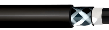
Cable Design and Construction: A Layer-by-Layer Analysis
The mechanical and chemical performance of a dynamic fiber optic cable is not determined by any single material choice. It emerges from the coordinated interaction of every layer in the cable cross-section.
Optical Fiber Configuration and Loose-Tube Construction
The cable houses 2 × 12 optical fiber cores in two color-coded loose tubes — tube 1 and tube 2 — each containing 12 fibers. Available fiber types include single-mode E9/125 (OS2), graded-index 50/125 µm multimode (OM2 through OM4), and graded-index 62.5/125 µm multimode (OM1), with fiber color coding per ANSI/TIA/EIA 598-A. Hybrid configurations combining, for example, 12 fibers of OM4 with 12 single-mode OS2 fibers in a single cable are available on request — a capability particularly valuable in modern port automation where a single cable run must serve both long-haul control network and high-bandwidth local network applications.
In a loose-tube construction, the optical fibers are housed inside a tube with an internal diameter larger than the fiber bundle, filled with a thixotropic gel or dry water-blocking element. This means the fibers are mechanically decoupled from the tube wall: when the cable bends, the tube deforms but the fibers redistribute within the tube space, finding their natural bending geometry rather than being forced to follow a fixed surface. This prevents the geometric distortions — micro-bends — that increase transmission attenuation. Loose-tube construction is specifically preferred over tight-buffered construction for dynamic reeling applications for precisely this reason.
TPE Tube Jacket
The individual fiber bundles are housed in loose-tube assemblies jacketed in thermoplastic elastomer (TPE). TPE combines the processing advantages of thermoplastics with rubber-like elastic recovery, ensuring the tube geometry is fully restored after each bending cycle. It is chemically inert, electrically isolating, and maintains its flexibility across the operational temperature range of the installation.
Synthetic Strain Relief Elements
Tensile loads in a reeling cable must be intercepted and distributed before they can reach the optical fiber elements. Within the cable core, synthetic strain relief elements run parallel to the fiber tubes, providing the primary load path during normal operation. These elements are dielectric — no metallic fiber — preserving the complete electromagnetic immunity of the cable construction.
Separating Tapes
Separating tapes isolate the tube-and-strain-relief assembly from the outer reinforcement braid, preventing abrasive contact between layers under dynamic loading and providing a clean interface for the inner sheath application.
Inner Sheath — Thermoplastic Elastomer PUR
The inner sheath provides the first layer of environmental containment for the optical fiber assembly. Polyurethane elastomers — particularly polyether-based grades used in outdoor dynamic cable applications — combine excellent resistance to hydrocarbon oils and fuels with broad temperature flexibility and elastic recovery under repeated deformation. The inner PUR layer also provides mechanical damping, absorbing vibrational energy before it reaches the fiber bundle.
High-Tech Multifilament Reinforcement Braid
The braid of high-technology multifilament yarns provides the primary tensile strength of the cable, enabling it to withstand the 1,500 N peak dynamic tensile loads of reeling operation. Two critical specifications govern this layer. First, the yarns are non-hygroscopic: they absorb less than 4–8% moisture by mass even at 100% relative humidity, compared to over 30% for older natural fibre constructions. This means the braid does not swell when wet, does not change mechanical stiffness in humid conditions, and does not support the progressive ionic contamination of splice points that wet fibers can promote. Second, the yarns are specified as low shrinkage: they do not contract under sustained tensile loading, which would otherwise cause the braid to progressively tighten around the optical fiber elements over the service life of the cable and introduce damaging compressive micro-bending stress on the fibers.
Outer Sheath — Reinforced Halogen-Free PUR
The outer sheath is the cable's primary interface with the environment. It is formulated from thermoplastic polyurethane reinforced with dielectric yarns and specified as halogen-free, with a black matt finish applied by inkjet marking.
The polyurethane outer sheath incorporates UV stabilizer packages — typically hindered amine light stabilizers (HALS) combined with UV absorbers such as benzotriazoles — that interrupt the photochemical radical chain reactions responsible for polymer degradation under UV irradiance. Carbon black pigmentation provides an additional UV screening mechanism. The combination enables unrestricted outdoor use, covering ozone, UV, and moisture exposure without service-life limitation.
The halogen-free formulation is critical for enclosed spaces such as crane cabin wiring routes and below-deck cable runs. In a fire event, halogenated polymer sheaths release hydrogen chloride gas — a dense, corrosive acid vapour that destroys electronic equipment and presents physiological hazard at low concentrations. Halogen-free compounds produce primarily CO₂ and water vapour, and the cable passes the single-cable vertical flame test per IEC 60332-1-2, meaning it will not propagate a flame along its length when ignited by a standardized burner.
Material Science Principles: Understanding PUR Performance
Polyurethane is a segmented block copolymer comprising alternating hard and soft segments. The hard segments — typically urethane or urea groups — form physical cross-links via hydrogen bonding, providing dimensional stability and chemical resistance. The soft segments — polyether or polyester polyol chains — provide elasticity and low-temperature flexibility.
This dual-phase microstructure explains why PUR simultaneously resists oil penetration (a function of chemical polarity incompatibility between the hard segments and hydrocarbon oils), maintains flexibility at −30 °C (a function of the low glass-transition temperature of the polyether soft segments), and withstands abrasion at temperatures above +60 °C (a function of the physical cross-link density). Polyether-based PUR grades, typically preferred for outdoor cable applications, also exhibit significantly better hydrolytic stability than polyester variants — directly addressing the moisture and salt spray challenges of marine and port environments.
This is why PUR outperforms the alternatives. PVC becomes brittle at low temperatures and has limited oil resistance without heavy plasticizer loading, which can leach over time and cause progressive stiffening. Standard neoprene rubber offers reasonable weather resistance but is mechanically weaker under sustained dynamic tensile loads. For outdoor dynamic cable applications where oil resistance, cold flexibility, abrasion resistance, and long-term UV stability must coexist in a single compound, PUR has become the engineering standard.
Salt Fog, Humid Heat, and Accelerated Ageing: What the Standards Say
The environmental qualification framework for industrial cables in harsh service draws on a combination of cable-specific standards and environmental testing protocols.
For oil resistance, the cable is qualified to IEC 60811-404, which specifies immersion in standardised reference oils at elevated temperature with post-immersion assessment of mass change, tensile strength retention, and elongation at break. Passing this test with a polyether-PUR compound demonstrates that the sheath will not swell beyond dimensional tolerances nor lose mechanical integrity in chronic hydrocarbon exposure.
Flame behaviour is qualified to IEC 60332-1-2, the single-cable vertical flame test. Salt fog resistance and humid heat performance are not always individually certificated on cable-level datasheets, as these properties derive from the polymer chemistry rather than cable architecture. However, polyether PUR formulations used in modern outdoor industrial cables are routinely tested to IEC 60068-2-52 (salt mist, cyclic) and IEC 60068-2-78 (damp heat) as part of compound qualification by the raw material manufacturer.
The individual optical fibers are qualified to IEC 60793-2-50 (single-mode, E9/125, category B1.3/OS2) and IEC 60793-2-10 (graded-index multimode, category A1), with single-mode fibers additionally conforming to ITU-T G.652 D and multimode fibers to ITU-T G.651. The cable is compliant with RoHS Directive 2015/863/EU and CPR 305/2011 (the EU Construction Products Regulation governing fire performance of cables in buildings and infrastructure).
Real-World Application Scenarios
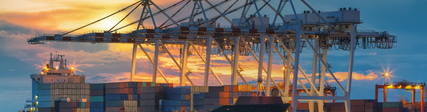
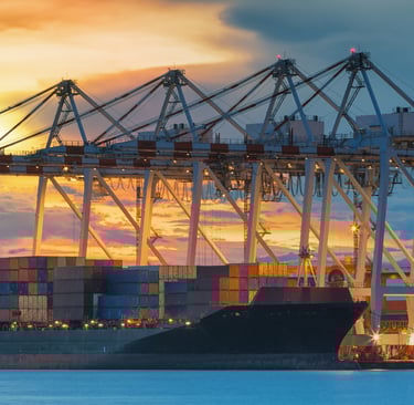
Container Port Gantry Cranes
Shore-to-ship and yard crane installations are among the most demanding reeling applications in existence. Cable reels on ship-to-shore cranes at major container terminals travel lateral distances of 50 to 100 metres per operating cycle, completing thousands of cycles per day over a service life of 15 to 25 years. The combination of salt spray from the marine environment, diesel and hydraulic oil contamination from the crane machinery, direct solar heating, and the sheer number of mechanical cycles makes this environment the definitive qualification test for any dynamic fiber optic cable. Single-mode fiber in the E9/125 OS2 configuration is typically selected for these installations, providing the long-distance capability needed to connect the moving crane to the quayside control system.
Automated Stacking Cranes in Modern Container Terminals
Fully automated rubber-tyred gantry cranes (RTGs) and rail-mounted gantry cranes (RMGs) in automated container terminals operate without human operators in the cabin. In many modern automated terminal designs, the cable reel is the sole physical data link between the terminal management system and the crane's onboard PLC. There is no wireless fallback, and the tolerance for communication downtime is effectively zero. These installations have driven the adoption of hybrid cable configurations — single-mode fibers for the low-latency control network plus multimode OM4 fibers for the high-bandwidth local automation network — in a single cable run, eliminating the complexity and failure-point risk of two parallel cable systems.
Offshore Platform Supply Cranes
Supply vessel handling cranes on fixed and floating offshore installations are exposed to continuous salt spray, H₂S-contaminated atmospheres at some hydrocarbon processing platforms, and extreme UV irradiance at lower latitudes. Cable flex cycles on offshore cranes are relatively infrequent compared to port cranes, but mechanical shock loads during vessel operations in heavy sea states can be high. The all-dielectric construction eliminates the cathodic protection interference issues that metallic-armoured cables create on offshore structures, and the PUR outer sheath provides the chemical resistance needed to survive the petrochemical environment.
Steel Mill Bridge and Ladle Cranes
Ladle and coil handling cranes in steel mills operate above open furnaces and continuous casting lines where radiant heat loads, metal splatter risk, and airborne ferrous particles create a uniquely aggressive environment. The cable's resistance to high ambient temperatures and its halogen-free flame-retardant formulation are particularly relevant here, as fire events in steel mill crane infrastructure can propagate rapidly unless cable materials are specified to resist flame spread.
Long-Distance Optical PROFIBUS Networks
In facilities where the control network must span kilometre-scale distances — large port terminals, chemical plants, automotive manufacturing complexes — optical PROFIBUS running on single-mode E9/125 fiber provides deterministic fieldbus communication immune to the electromagnetic interference that industrial plants generate. The CRANE PUR FO cable in its single-mode configuration serves these installations not only as a crane cable but as the durable, mechanically protected fiber optic infrastructure for the entire LDN backbone.
Installation Considerations for Long Service Life
Respecting the Minimum Bending Radius
The 250 mm minimum bending radius is a materials-derived constraint, not an arbitrary safety factor. Bending an optical fiber beyond its critical radius induces macro-bending losses through mode field expansion in single-mode fiber, and micro-bending losses through geometric deformation of the core-cladding interface in both fiber types. Cable guide systems on reels must be designed to ensure the cable never transits a bend tighter than this radius at any point in the travel range, including at the drum flange transition and at the cable exit point from the reel housing.
Managing Tensile Loads
The 1,000 N continuous operational load and 1,500 N peak dynamic tensile load define the mechanical design envelope of the strain relief system. Applications with very large free-hanging cable spans subject to aerodynamic buffeting — for example, a long-travel crane in a high-wind coastal environment — require engineering review to assess whether cable catenary management or additional festoon guide supports are required to keep in-service loads within the cable rating.
Temperature Commissioning in Cold Climates
The operational temperature floor for free movement is −30 °C, not the −40 °C floor specified for transportation and storage. At temperatures between −30 °C and −40 °C, the cable must not be flexed or spooled. The polymer sheath materials remain above their glass transition temperatures for static conditions in this range, but dynamic loading at these temperatures reduces the safety margin against brittle fracture to an unacceptable level. In cold climate installations, it is good practice to allow the cable to reach operating temperature — through either ambient warming or a brief low-speed reel exercise cycle — before commencing full-speed operations on cold mornings.
Field Termination and Splice Points
The cable's outer sheath provides excellent environmental resistance along its run, but termination and splice points are the most vulnerable locations in any cable system. In exposed outdoor or maritime environments, all connector housings and splice closures must be rated to at least IP67. Fusion splice closures should use gel-sealed or heat-shrink re-enterable designs rather than mechanical closures that can allow moisture ingress during the pressure cycling associated with temperature changes. Routing termination points inside weatherproof junction boxes wherever the application permits is strongly recommended, reserving the cable's direct weathering performance for the cable runs themselves.
Advantages of Fiber Optics Over Copper in Crane Communication
The advantages of optical transmission over copper in crane and industrial environments can be understood at the physics level, not merely as a marketing comparison.
Electromagnetic immunity is inherent, not engineered. A copper cable in proximity to large variable-frequency drives requires careful shielding, grounding, and often physical separation to maintain signal integrity. A fiber optic cable is simply immune — there is no electrical conductor to receive induced noise. In crane machinery rooms where multi-megawatt drives operate in close physical proximity to the communication cable runs, this property alone is sufficient justification for fiber.
Bandwidth scales without infrastructure change. A single-mode fiber installed today for a 1 Gbps PROFIBUS application can support 100 Gbps Ethernet tomorrow with a transceiver change and no cable replacement. Copper infrastructure locked to a given bandwidth class requires full cable replacement to upgrade. For installations with service lives of 20 or more years, this future-proofing has significant economic value.
Distance limitations effectively disappear. Single-mode fiber supports transmission over 10 km or more at full bandwidth, compared to the 100-metre limit of copper Ethernet. Large terminal installations spanning a kilometre or more between control rooms and remote crane positions require copper signal repeaters or active electronics at intermediate points — infrastructure that itself requires maintenance and represents failure points. Single-mode fiber eliminates this entirely.
Galvanic isolation is inherent. Large steel crane structures spanning significant distances develop ground potential differences that create ground loop currents in copper conductors, corrupting low-level signals and accelerating corrosion. All-dielectric fiber carries no current and is completely immune to this failure mode.
The weight advantage is meaningful at scale. At approximately 200 kg/km, the CRANE PUR FO cable is substantially lighter than an equivalent copper multi-conductor industrial cable, reducing the mechanical load on cable reels and festoon systems and lowering the inertial forces that contribute to dynamic tensile loading during reel acceleration and deceleration.
Conclusion
Modern crane systems do not merely move loads — they are networked industrial machines generating and consuming data continuously, with communication reliability that is inseparable from operational safety. In this context, the cable that carries the communication signal is not a commodity item to be selected on price. It is a critical component whose failure mode must be understood, whose material properties must be matched to the specific environmental stressors of the installation, and whose service life must be measured against the expected service life of the equipment it connects.
The CRANE PUR FO 2×12 …/125 cable addresses this requirement through an engineered convergence of optical transmission technology and industrial cable material science. Its loose-tube fiber management, dielectric strain relief, dual-layer PUR sheathing, multifilament braid reinforcement, and halogen-free construction each address specific failure mechanisms — tensile fatigue, bending fatigue, oil absorption, UV degradation, moisture ingress, and salt-induced chemical attack — that would otherwise limit service life in the environments where these cables are deployed.
As port terminal automation advances toward fully autonomous operations, edge-computing-based machine vision, and dense real-time sensor networks, the data bandwidth and latency requirements of crane communication will continue to grow. Fiber optic cables specifically designed for the dynamic crane environment are not merely a present solution. They are the physical infrastructure on which the next generation of intelligent material handling will be built.
Frequently Asked Questions
Q: What makes PUR a better sheath material than PVC or rubber for outdoor crane cables?
PVC becomes brittle at low temperatures and has limited oil resistance without heavy plasticizer loading, which can leach over time and cause progressive stiffening. Standard neoprene rubber offers good weather resistance but is mechanically weaker under sustained dynamic tensile loads. Polyurethane elastomers — particularly polyether-based grades — combine excellent abrasion resistance, broad temperature flexibility from −30 °C to +80 °C, strong resistance to hydrocarbon oils and fuels, inherent UV stability when properly stabilized, and the elastic recovery needed for repeated bending on cable reels. For outdoor dynamic cable applications, PUR has become the engineering standard precisely because it simultaneously satisfies requirements that individually rule out every alternative compound.
Q: Can this cable be used in saltwater spray zones on offshore platforms or port quayside installations?
Yes. The cable is rated for unrestricted outdoor use including resistance to ozone, UV, and moisture. The all-dielectric construction — no metallic elements anywhere in the cross-section — eliminates galvanic corrosion as a failure mode, which is the primary mechanism by which metallic-armoured cables fail in salt spray environments over time. The polyether PUR sheath is hydrolytically stable and does not deteriorate on sustained salt water contact. The non-hygroscopic reinforcement braid maintains its mechanical properties wet or dry, and does not support the progressive ionic contamination of splice points that absorptive fibre constructions can promote. For truly immersed installation points, additional IP-rated enclosure protection at termination locations is recommended.
Q: How does loose-tube fiber construction protect against micro-bending losses in dynamic applications?
In a loose-tube construction, the optical fibers are housed inside a tube with an internal diameter larger than the fiber bundle, either gel-filled or fitted with a dry water-blocking element. This means the fibers are mechanically decoupled from the tube wall. When the cable bends, the tube deforms but the fibers can redistribute within the tube space, finding their natural bending geometry rather than being forced to follow the tube's outer surface. This prevents micro-bending — microscopic geometric distortions of the fiber core that increase transmission attenuation and, in severe cases, cause stress fractures. Loose-tube construction is specifically preferred over tight-buffered construction for dynamic reeling applications for this reason, and is standard practice in all quality industrial fiber optic cables designed for continuous movement.
Q: What is the difference between E9/125 single-mode and G50/125 multimode fiber for industrial communication, and how do I choose?
Single-mode fiber with a 9 µm core guides only one light propagation mode, eliminating modal dispersion entirely. This enables transmission over tens of kilometres and supports very high bit rates at any distance. It is the correct choice for long-distance links — inter-terminal communication, LDN backbones, and any link longer than approximately 300 to 550 metres. Single-mode sources (lasers) are slightly more expensive than multimode sources. Graded-index multimode fiber with a 50 µm core accepts multiple propagation modes and works with lower-cost VCSEL sources. OM4-grade 50/125 µm fiber supports up to 100 Gbps over approximately 150 metres, making it ideal for intra-crane local networks and machine control links within a single crane structure. The availability of both fiber types in one cable — the hybrid 12×G50 + 12×E9 configuration — allows a single cable run from a control room to a crane to serve both the long-haul control network and the high-bandwidth local automation network without two separate cable deployments.
Q: What are the installation temperature limits and why do they differ from the operating temperature range?
The storage and transport range of −40 °C to +80 °C reflects the temperatures at which the cable can exist in a static, stress-free condition without permanent damage. The lower operational limit of −30 °C for free moving and festoon applications reflects the temperature at which the polymer materials retain sufficient toughness to withstand repeated bending without brittle fracture under dynamic loads. Below −30 °C, even a well-formulated PUR compound will show increased stiffness and reduced impact resistance under the stress of reeling. This does not mean the cable fails instantly at −32 °C — it means the safety margin against brittle cracking during mechanical stress becomes unacceptably thin. In cold climate installations, allowing the cable to reach operating temperature before commencing full-speed reeling operations is always recommended.
Q: Why is the reinforcement braid specified as non-hygroscopic and low shrinkage?
Non-hygroscopic means the reinforcement yarns do not absorb atmospheric moisture. This matters for three reasons: absorbed moisture causes fibers to swell, potentially compressing the optical fiber bundle and inducing micro-bending losses; a wet reinforcement braid changes in mechanical stiffness, affecting the dynamic response of the cable; and dry fibers do not introduce ionic contamination at splice points or promote the biological fouling possible in permanently damp fibre constructions. Low shrinkage means the reinforcement yarns do not contract under sustained tensile loading — a property critical to preventing the reinforcement from progressively tightening around the optical fiber elements over years of service and introducing compressive bending stress on the fibers that would continuously degrade transmission performance.
Q: How should this cable be terminated and spliced in exposed outdoor environments?
The cable's outer sheath provides excellent environmental resistance along its run length, but termination and splice points are the most vulnerable locations in any outdoor cable installation. In exposed maritime or industrial outdoor environments, all connector housings and splice closures must be rated to at least IP67. Connectors should use waterproof field-assembly types with appropriate ingress protection ratings, or factory-installed assemblies with pre-qualified environmental ratings. Fusion splice closures should use gel-sealed or heat-shrink re-enterable designs rather than mechanical closures, which can admit moisture during the pressure cycling caused by temperature changes over the diurnal cycle. Routing termination points inside weatherproof junction boxes wherever the application allows is strongly recommended.
Q: Is the cable halogen-free and why does this matter in crane applications?
Yes — the outer sheath is formulated as halogen-free. In a fire event, PVC and other halogenated polymer sheaths release hydrogen chloride gas — a dense, highly corrosive acid vapour. In the enclosed machinery spaces common to crane gantries, overhead bridge cranes, and below-deck cable runs on offshore platforms, this gas rapidly attacks electronic control equipment, corrodes exposed metal surfaces, and creates physiological hazard for personnel at low concentrations. Halogen-free compounds produce primarily CO₂ and water vapour — far less corrosive and less acutely toxic. The IEC 60332-1-2 flame test addresses whether the cable spreads a flame; the halogen-free specification addresses the chemical toxicity of the combustion products. Both properties are relevant to crane fire safety, and both are addressed in this cable's specification.
Technical specifications subject to revision without prior notice. Attenuation values in the finished cable may deviate from standard optical fiber specifications due to manufacturing variables.
Port crane cables | Mining cables | Reeling cables | Trailing cables | Festoon cables | Heavy-duty power cables | Medium voltage cables | Offshore crane cables | Underground mining cables | Dragline cables | Shearer cables | Container handling cables | STS crane cables | RTG cables | Mobile equipment cables | Armored cables | Flexible power cables | VFD cables | Submersible cables | Cold resistant cables | Abrasion resistant cables | Flame retardant cables | Marine environment cables | Opencast mining | Underground operations
© 2006 All rights reserved.
[INDUSTRIAL_CABLES]
INDUSTRIAL GRADE CABLE SYSTEMS | PORT & MINING SOLUTIONS
TEL: +86 153 7530 2641 |MAIL: hongjing.Wang@feichuncables.com