Dust and Sand Abrasion: Protecting Crane Cables in Desert-Adjacent Marine Terminals
Explore how sand abrasion damages crane cables in UAE coastal ports and desert terminals, and discover abrasion-resistant materials, failure modes, and protection strategies.
hongjing.Wang@Feichun
7/6/202618 min read
1. Introduction
Within the global logistics network, the maritime terminals of the United Arab Emirates and the wider Gulf Cooperation Council region serve as critical links for international trade. Ports such as Jebel Ali in Dubai, Khalifa Port in Abu Dhabi, and other major hubs across the Arabian Gulf handle millions of twenty-foot equivalent units annually, operating continuously to keep supply chains moving. However, maintaining this high operational efficiency requires equipment to withstand one of the most chemically and mechanically aggressive environments on Earth.
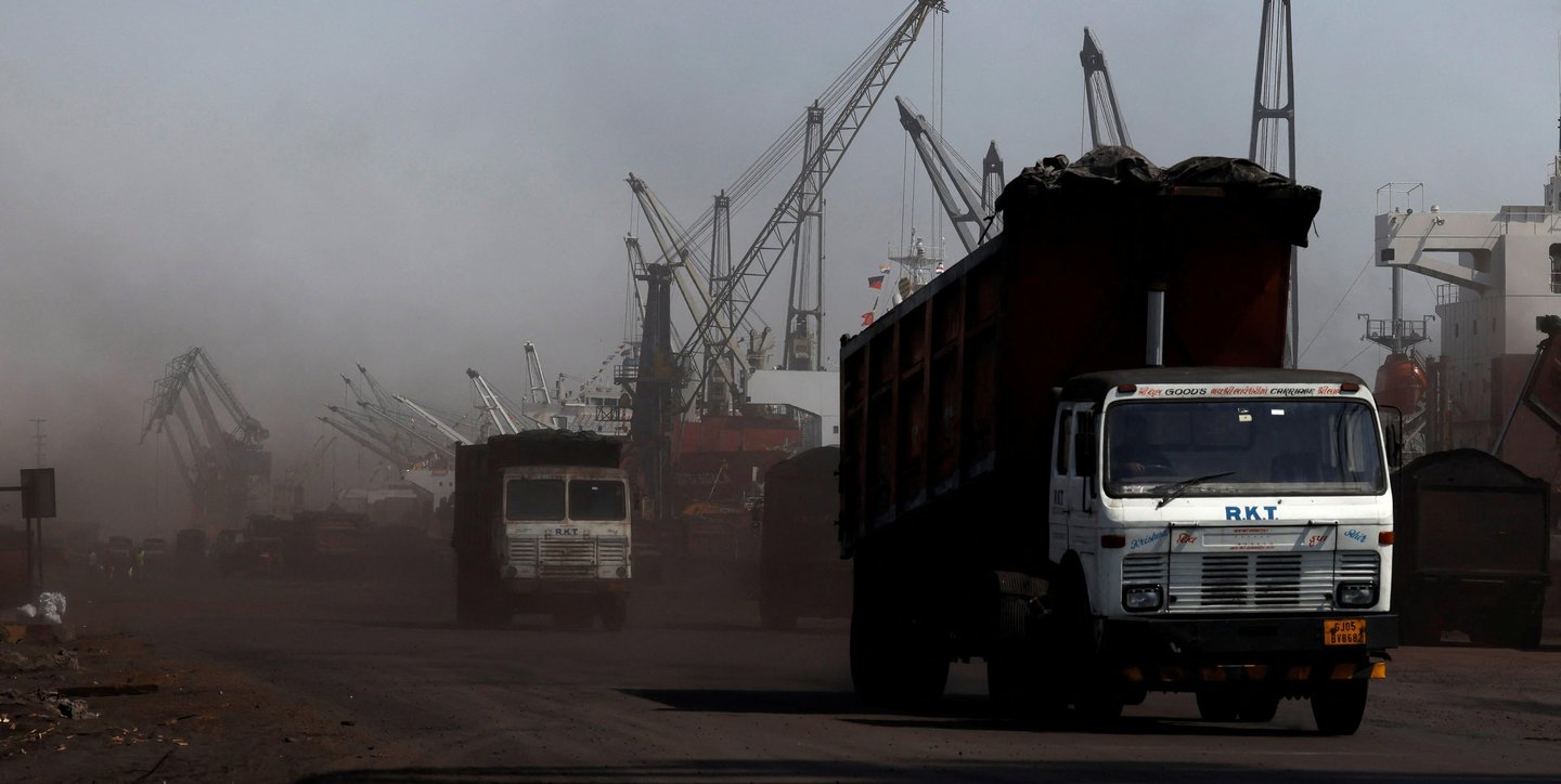
In these desert-adjacent marine terminals, heavy-duty container handling equipment—particularly Ship-to-Shore cranes, Rail-Mounted Gantry cranes, and Rubber-Tired Gantry cranes—is exposed to a severe combination of environmental stresses. Unlike typical European or North American ports that primarily deal with moisture and salt spray, Gulf terminals face a complex mix of intense solar radiation, high marine humidity, persistent salt air, and a heavy load of wind-borne desert sand and fine ambient dust.
When these airborne micro-abrasives settle onto the moving parts of a crane, they do not remain static. As the crane cycles continuously to load and unload vessels, its medium-voltage power cables and high-speed fiber-optic control lines are subjected to relentless mechanical motion. The cables are reeled, unreeled, curved, and dragged through guides at high speeds, trapping the abrasive sand grains against the polymer surfaces. This environment is especially common in terminals located near open desert corridors and coastal industrial zones, where the prevailing winds constantly resupply the port with fresh, sharp silica particles.
For port engineering directors, maintenance managers, and procurement officers across the GCC, understanding and mitigating this specific wear mechanism is essential. This article serves as a practical, engineering-focused guide to analyzing how sand abrasion compromises cable integrity, comparing the performance of specialized jacket compounds, and implementing effective protection strategies to maximize cable service life and prevent costly operational downtime.
2. Why Sand Abrasion Is a Real Problem in Gulf Ports
To understand the scale of mechanical wear in Gulf marine terminals, one must look at the regional geography and atmospheric patterns. The Arabian Peninsula is home to some of the largest contiguous sand deserts in the world, including the Rub' al Khali (the Empty Quarter). Wind-blown sand research and geological monitoring in the UAE have documented active sand transport across these vast desert corridors. This research confirms that the region experiences a significant and continuous airborne sand load, rather than just static ground dust. Under the influence of regional wind systems, such as the seasonal Shamal winds that blow from the north and northwest, millions of tons of fine, mineral-rich particles are lifted high into the atmosphere and carried over long distances, directly intersecting with coastal industrial zones.
When these airborne sand plumes reach a marine terminal, the environmental interaction changes. In a dry inland desert, sand particles remain loose and free-flowing, often blowing off smooth surfaces as quickly as they arrive. However, in a coastal port environment, this fine silica-rich sand mixes with high marine humidity and airborne sea salt. The moisture in the air creates a thin, microscopic film of condensation on exposed machinery, structures, and cable jackets. When dry desert sand contacts these damp surfaces, it sticks, forming a gritty, abrasive paste that clings to the equipment.
This persistent contamination creates a continuous source of abrasion for crane cables, particularly along exposed cable runs, festoon systems, and large reeling drums. As the crane operates, it cannot escape this abrasive matrix. Every movement of the trolley or travel of the gantry forces the cable to interact with the trapped sand grains, turning what should be a smooth mechanical transition into a destructive grinding process.
3. Sand Size and Abrasion Behavior
From an engineering perspective, the destructiveness of wind-borne sand is directly related to its physical characteristics. The airborne particulate matter found in Gulf port environments typically falls within a specific abrasive particle range of 50 to 200 micrometers. This particle size distribution is critical to analyze because it dictates how the sand behaves when interacting with industrial machinery.
Particles within this 50 to 200 micrometer range are small enough to act almost like a fluid. They easily penetrate small clearances, migrating deep into cable guide systems, interior channels of energy chains (cable tracks), rollers, and the compact interfaces of cable reeling drums. Standard mechanical seals and basic weather stripping often fail to stop particles of this size. At the same time, these grains are large and heavy enough to carry substantial kinetic energy when driven by the wind.
More importantly, these sand particles consist primarily of quartzose silica ($SiO_2$), a mineral with a hardness rating of 7 on the Mohs scale. This makes the dust harder than most structural polymers, standard rubbers, and even some soft metals used in industrial machinery. When the wind speed increases during seasonal dust storms or afternoon thermal shifts, it raises the impact energy of these hard particles. The result is a continuous surface bombardment of the exposed crane cables, rather than an isolated wear event. Over months of exposure, millions of these micro-impacts progressively degrade the outer layer of the cable jacket, wearing away the material through a steady process of erosion.
4. Mechanical Wear Mechanisms
The degradation of a port crane cable by sand contamination is a multi-stage mechanical process. It involves several distinct wear mechanisms that operate simultaneously wherever the cable experiences movement, pressure, or friction.
Micro-Cutting and Surface Abrasion
The primary mechanism at play on a bare cable jacket is surface abrasion through micro-cutting. Because wind-borne sand grains are highly angular with sharp, fractured edges, they act like miniature cutting tools. When a sand particle is pressed against the outer sheath of a cable under the tension of a reeling drum or the weight of a festoon sag, the sharp edge digs into the polymer. As the cable moves, the particle plows a microscopic furrow along the surface, shaving away a tiny volume of the jacket material. Over millions of operational cycles, these individual micro-cuts accumulate, leading to measurable material loss and a uniform reduction in sheath thickness.
Grinding in Cable Guide Systems
This abrasive action accelerates significantly within the cable guide systems, rollers, and sheave wheels of the crane. As a cable passes through a guide or rolls over a sheave, it creates a localized pressure zone. Sand particles trapped between the moving cable jacket and the rigid surface of the guide roller are subjected to high compressive forces. Instead of blowing away, the sand grains are embedded into the interface, acting exactly like an industrial grinding compound or sandpaper. Every acceleration and deceleration of the crane trolley forces the cable to slide through this abrasive trap, rapidly wearing down the outer sheath.
Festoon and Reel Sliding Wear
The specific geometry of crane cable management systems introduces targeted wear profiles:
Festoon Systems: In a classic festoon arrangement, cables hang in long loops supported by mobile trolleys. As the main crane trolley travels along the runway, these loops rapidly expand and compress. The cables experience intense flexing at the saddle supports, where wind-borne sand gathers in the crevices. The continuous shifting and rubbing against the metal or polyurethane saddles under a heavy sand load creates localized wear zones, often leading to flattening or deep scoring of the cable profile at the support points.
Reeling Systems: For long-travel gantry movements and vertical hoist configurations, cables are wound tightly onto motorized reels. Here, sliding wear occurs as the cable guides direct the cable onto the drum layer by layer. If sand is present on the drum or the lower layers of the cable, the incoming cable is forced against a gritty surface under significant mechanical tension. This creates interlayer abrasion, where the jackets of adjacent cable turns rub against each other with sand trapped in between, damaging the outer sheath even when the cable is supposedly static on the reel.
Because abrasion is a cumulative process, this mechanical wear is often difficult to detect in its early stages. The cable may appear perfectly operational for the first several months of service, showing only a slight loss of its factory surface gloss. However, beneath the surface, the structural integrity of the outer jacket is steadily declining as the sharp silica particles continuously wear away the protective material.
5. Material Comparison for Abrasion Resistance
Given the severe mechanical wear caused by sand contamination, selecting the correct polymer compound for the cable's outer jacket is one of the most critical decisions a port engineer can make. Standard commercial cable jackets designed for indoor industrial use or temperate climates quickly degrade when deployed in a desert-adjacent marine terminal. The outer layer requires a specialized jacket compound engineered specifically for high mechanical tensile strength, superior cut resistance, and excellent long-term abrasion resistance.
Polyurethane (PUR) Outer Sheaths
For highly dynamic applications involving continuous reeling, fast festoon cycling, and exposure to abrasive dust, Polyurethane (PUR) is often preferred by cable designers. PUR is an engineered elastomer characterized by exceptional mechanical durability. It features a high molecular density that gives it excellent resistance to micro-cutting and tearing.
When a sharp silica particle impacts a high-grade PUR jacket, the material's natural elasticity allows it to deform temporarily and absorb the energy of the particle, rather than fracturing or cutting. Once the stress is removed, the PUR rebounds to its original shape. This high resilience makes PUR extremely effective at resisting the continuous grinding action found in cable tracks and on reeling drums. Additionally, PUR outer sheaths maintain their mechanical properties across a wide temperature range, ensuring the cable does not soften or become prone to gouging during hot afternoon operations in the Gulf, where ambient temperatures can exceed 50°C.
Chlorinated Polyethylene (CPE) and Rubber Compounds
Chlorinated Polyethylene (CPE) and specialized synthetic rubber compounds (such as heavy-duty polychloroprene or ethylene propylene rubber formulas) are also widely used in port environments, particularly for larger, heavy-core power distribution cables.
CPE Jackets: CPE provides a balanced combination of chemical resistance, flame retardancy, and mechanical toughness. It handles exposure to oils, ozone, and ultraviolet radiation exceptionally well, making it a stable choice for outdoor marine environments. However, its ultimate resistance to pure sand abrasion is highly dependent on the specific formulation and the density of the curing agents used during manufacturing.
Heavy-Duty Rubber Compounds: Specialized rubber sheaths provide excellent flexibility and are highly resistant to twisting and torsional stresses, which is vital for vertical tender cranes and complex spatial movements. However, standard industrial rubber compounds tend to have a lower surface slickness compared to PUR. This higher coefficient of friction can cause sand particles to catch and drag across the surface more easily, potentially increasing the rate of micro-cutting unless the compound is explicitly modified with anti-abrasion additives.
The Role of Shore Hardness
When evaluating candidate jacket materials, technical procurement teams frequently look to Shore hardness as a key practical reference for identifying a tough outer jacket. For desert-port applications, an outer jacket hardness in the range of Shore A85 to Shore A95 is typically targeted.
Materials within this hardness range provide the necessary structural rigidity to resist the penetration of sharp sand grains, while maintaining enough structural flexibility to handle tight bending radii around sheaves and drums without cracking. A jacket that is too soft (below Shore A80) allows sand grains to embed deeply into the polymer matrix, turning the cable jacket itself into an abrasive surface that degrades guide rollers and adjacent cables. Conversely, a jacket that is too hard (above Shore D50) becomes brittle, increasing the risk of stress cracking during high-speed flexing.
Comprehensive Material Evaluation
It is important to note that focusing on mechanical tensile strength alone is not enough to guarantee long-term survival in a sandy environment. Cable survivability requires a holistic design approach where several performance metrics are optimized together:
$$\text{Cable Survivability} \propto \text{Abrasion Resistance} + \text{Cut Resistance} + \text{Crack Resistance} + \text{Tensile Strength}$$
A cable jacket might possess impressive tensile strength when pulled in a straight line in a laboratory, but if it lacks cut and tear resistance, a single deep score from a sharp quartz particle can propagate into a catastrophic split during routine bending. Therefore, the polymer matrix must be engineered to resist both the initial micro-penetration of the sand and the subsequent growth of surface micro-cracks under continuous mechanical cycling.
6. Typical Failure Modes
When a crane cable is deployed without adequate protection or the correct material formulation in a desert-adjacent port, the continuous sand abrasion triggers a predictable sequence of structural failures. Recognizing these typical failure modes early allows maintenance teams to intervene before a catastrophic electrical event occurs.
Phase 1: Sheath Thinning
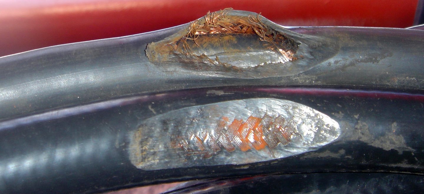
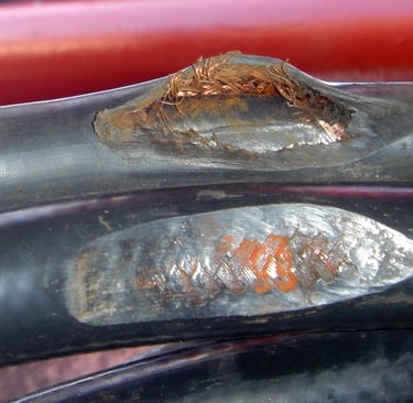
The earliest visible sign of sand abrasion is a uniform thinning of the outer outer sheath. As the micro-cutting mechanism shaves away the polymer matrix layer by layer, the overall outer diameter of the cable begins to decrease. This thinning is rarely perfectly uniform; it concentrates on the sections of the cable that experience the highest contact pressures, such as the sides that ride directly against guide rollers or the bottom layer that bears the weight of the cable on a reeling drum. At this stage, the cable continues to perform its electrical duties perfectly, masking the underlying structural degradation from operators who rely solely on digital telemetry.
Phase 2: Armor Exposure
In reinforced cable constructions designed for high tensile loads, a metallic or high-strength textile strength member—such as a galvanized steel wire braid, an aluminum shield, or an aramid anti-torsion braid—is embedded beneath the outer jacket. As the sand abrasion removes the outer protective polymer layer, it eventually breaches the jacket completely, leading to localized armor exposure.
Once the reinforcing braid is exposed to the open air, its structural utility drops. In the case of steel wire armoring, the mechanical protection is compromised as individual wires are ground down by the sand. More importantly, breaching this outer layer removes the primary barrier against the surrounding environment.
Phase 3: Micro-Cracking and Moisture Ingress
As the cable continues to flex over sheaves and drums with a thinned, structurally weakened outer sheath, the localized stress concentrations cause microscopic fractures to develop along the surface furrows. These micro-cracks rapidly expand under the thermal expansion and contraction cycles common in the Gulf region, where daytime surface temperatures on machinery can vary widely between day and night.
Once these micro-cracks form, the path is cleared for the next destructive phase: moisture ingress. In coastal terminals, the ambient air is heavily saturated with water vapor and highly corrosive sea salt ions ($\text{Na}^+$ and $\text{Cl}^-$). Capillary action draws this saline moisture through the micro-cracks and directly into the internal structure of the cable.
Phase 4: Internal Deterioration and Failure
With moisture inside the cable core, internal degradation accelerates:
Corrosion of Shields and Ground Conductors: The salt water reacts with copper grounding braids and metallic shields, initiating galvanic corrosion that increases electrical resistance and compromises shielding effectiveness.
Insulation Degradation: The moisture migrates toward the primary conductor insulation (such as XLPE or EPR). Over time, under the influence of high electrical voltage stresses, the trapped moisture causes the formation of water trees—microscopic void networks within the insulation that slowly grow until they cause a dielectric breakdown.
Short Circuits and Flashovers: The final result is a sudden phase-to-phase or phase-to-earth short circuit, leading to an immediate power failure, equipment trip, and unscheduled port downtime.
In desert-adjacent coastal terminals, this specific combination of sand abrasion and moisture ingress is dangerous because it transforms a purely mechanical surface wear issue into a deep, systemic electrical failure. The outer sheath is no longer able to function as a complete barrier, leaving the vulnerable internal components exposed to a hostile environment.
7. Real Port Environment in the Middle East
To appreciate the operational conditions that crane cables must survive, it helps to look at the physical environment of major marine terminals in the United Arab Emirates, with a particular focus on the coastal industrial sectors where the desert landscape directly interfaces with heavy maritime operations.
A clear example of this environment is the Jebel Ali industrial area and its expansive port complex in Dubai. Jebel Ali is one of the largest man-made harbors in the world and a high-traffic hub for global logistics. The geography of the site is unique: to the west and south, the port infrastructure directly borders open coastal desert terrain and arid industrial buffer zones. This layout creates an uninhibited pathway for wind-borne dust and sand to blow directly into the container yards and berth spaces.
An operational terminal in this zone experiences several overlapping environmental factors:
Constant Heavy Truck Movement: Internal terminal tractors, container haulers, and external freight trucks move continuously through the yard. This high-volume traffic generates mechanical turbulence that resuspends settled ground dust, keeping fine silica particles circulating in the air at crane level.
Exposed Cable Routes: Many cranes feature long-travel gantry systems where cables lie in exposed concrete trenches running parallel to the shipping berths. These ground-level trenches act as natural collectors for wind-blown sand, ensuring that the cable is dragged through an accumulation of abrasive material during every long-travel movement.
High Ambient and Solar Temperatures: Sunlight heats the dark polymer jackets of crane cables well beyond ambient air temperatures, often reaching 70°C or higher. This thermal stress can soften lower-grade plastics, making them more susceptible to gouging and micro-cutting by sharp sand grains.
Intense Industrial Runoff and Dust: Nearby industrial installations—including aluminum smelters, cement plants, and manufacturing facilities within the free zone—contribute additional chemical particulates to the atmosphere, which mix with the sand and salt air to form a highly reactive surface deposit.
These severe operating conditions are not unique to Jebel Ali; they are a defining characteristic of maritime logistics hubs across the GCC region. From the industrial ports of Industrial City Abu Dhabi (ICAD) and the expanding berths of King Abdulaziz Port in Dammam, Saudi Arabia, to the coastal terminals of Shuwaikh in Kuwait and Sohar in Oman, crane cables face the same environmental challenge: surviving the intense friction of high-capacity container handling while operating in a continuous matrix of desert sand and marine humidity.
8. Real-World Case Context
The clear need for high component reliability in Gulf ports is underscored by analyzing historical operational incidents in the region. A notable example is the significant crane accident that occurred at Jebel Ali Port Terminal 1.
In this incident, a large container vessel drifted out of its approach channel during berthing maneuvers and collided directly with the harbor quay, striking a prominent shore-side Ship-to-Shore gantry crane. The force of the impact caused structural failure of the crane, resulting in its collapse onto the quay wall and an adjacent container yard, which led to a secondary impact with a second crane and caused several injuries to shore personnel.
While the direct cause of this specific accident was a mechanical or navigational steering failure on board the vessel rather than an electrical fault, the event provides vital context for port engineers regarding the extreme operational risks and economic vulnerabilities present at heavy container terminals. A single structural or component failure on a Ship-to-Shore crane does not simply require a routine maintenance repair; it has the potential to trigger a cascading operational incident that compromises worker safety, damages multi-million-dollar assets, and shuts down an entire commercial berth for months.
When a terminal crane is taken out of service—whether due to a rare ship collision or routine, preventable downtime caused by an aborted cable insulation failure—the financial penalties are severe. Berth congestion increases, shipping lines face costly delays, and the port operator loses revenue to competing regional hubs.
This reality emphasizes why every sub-component of a crane system, including the power and control cables, must be engineered for strict reliability and physical survivability under harsh conditions. Preventive design, meticulous material selection, and robust environmental protection are not optional luxuries; they are essential engineering practices required to maintain safe, steady, and predictable operations at high-throughput global gateways.
9. Protection Strategies
Protecting crane cables from sand abrasion and premature failure requires a multi-layered engineering approach. Port operators cannot alter the regional wind patterns or eliminate desert dust, but they can minimize its impact by combining proper material selection, protective physical routing, and structured maintenance practices.
1. Specification of High-Grade Jacket Materials
The first and most effective line of defense is specifying high-grade, abrasion-resistant jacket materials during the procurement phase. For exposed, high-dynamic sections of the crane—such as the main vertical festoons or high-speed reeling systems—standard rubber or commercial PVC should be replaced with specialized Polyurethane (PUR) formulations featuring a verified Shore hardness between A85 and A95. The high mechanical tensile strength and structural resilience of PUR ensure that the outer sheath can deflect sharp silica particles and resist the continuous micro-cutting action of trapped dust without experiencing rapid material loss.
2. Implementation of Protective Routing and Enclosures
Modifying the physical path of the cable can significantly reduce its exposure to airborne contaminants:
Sealed Cable Tracks (Energy Chains): For horizontal trolley movements along the crane boom, open festoon arrangements can be replaced with enclosed plastic or stainless-steel energy chains equipped with integrated dust-protection seals or overlapping covers. These enclosures shield the internal cables from direct wind-blown sand and prevent dust from accumulating on the individual jackets.
Covered Ground Trenches: For long-travel gantry systems where cables lie at ground level, the open concrete trenches should be fitted with heavy rubber belt covers or automatically elevating brush seals. These mechanical barriers allow the crane's cable guide arm to pass through during movement while keeping wind-blown sand, yard debris, and industrial dust out of the storage channel.
Optimized Roller and Sheave Design: Guide rollers and sheaves should utilize smooth, non-porous materials, such as high-density polyurethane or polished stainless steel, which resist sand embedding. Rollers must be fitted with sealed, self-lubricating bearings to prevent sand from seizing the rotating mechanism, which would transform a rolling contact into a destructive sliding contact.
3. Structured Maintenance and Cleaning Protocols
To combat the cumulative nature of sand wear, terminal maintenance plans should include dedicated dust-management procedures:
Regular Mechanical Cleaning: High-speed cable reeling paths and guide channels should be equipped with automated nylon brush sets or high-pressure air knives that continuously clear loose sand from the cable surface before it winds onto the drum.
Laser Sheath-Thickness Testing: During scheduled maintenance windows, technicians should utilize portable laser micrometer gauges or ultrasonic thickness testers to measure the outer diameter of critical cables at high-wear zones. Tracking this data allows engineers to plot the actual rate of sheath thinning and schedule replacements before the internal armor layer becomes exposed.
Targeted Replacement Intervals: Instead of operating a cable until an electrical fault occurs, ports should establish predictive replacement intervals based on operational cycle counts and historical material wear rates specific to the sand load of the terminal.
Ultimately, port design teams must prioritize physical survivability in sandy environments alongside core electrical performance metrics. A cable with excellent dielectric properties is of little use if its outer protective barrier is worn away by sand within its first year of service.
10. Materials and Testing Reference
To ensure that industrial cables can withstand the abrasive conditions of a desert-adjacent terminal, procurement teams must look past basic product brochures and verify performance against recognized international standard testing frameworks. The primary global authority governing testing methods for electric and optical fiber cables used in industrial applications is the International Electrotechnical Commission (IEC) 60811 series.
The IEC 60811 standard outlines precise laboratory procedures for testing the non-metallic compounds used in cable jackets and insulation layers. These standardized tests verify critical material properties, including:
Initial mechanical tensile strength and ultimate elongation at break.
Long-term thermal aging behavior in controlled ovens to simulate decades of outdoor exposure.
Resistance to environmental stress cracking when exposed to surface active agents, oils, and chemical contaminants.
Low-temperature flexibility to ensure the material does not fracture during unexpected temperature drops or high-impact events.
While the IEC 60811 series provides a valuable framework for comparing the baseline physical properties of different polymer families, interpreting these laboratory metrics for desert-port applications requires engineering judgment. Standard tensile tests pull a clean polymer sample under controlled laboratory conditions, which does not fully capture the complex, real-world wear caused by continuous sand abrasion, wind bombardment, and shifting coastal humidity.
Therefore, for projects located in high-abrasion zones like the GCC, standard material test results should be interpreted alongside data from specialized abrasion tests—such as the needle abrasion test or the rotating drum abrasion method (often referenced under ISO 4649 or equivalent standards). These tests subject the material to direct contact with a calibrated abrasive surface under a specified load, providing a clearer indication of how a PUR or CPE compound will handle real-world silica exposure. Sourcing teams should require manufacturers to provide comprehensive third-party test evidence from accredited independent testing houses, ensuring the cable’s design claims are fully verified by empirical data.
11. Procurement Checklist
When sourcing crane cables for high-capacity maritime terminals in the GCC, relying on standard generic specifications can lead to early material selection errors. Technical procurement teams should utilize a rigorous, application-specific checklist to evaluate potential manufacturing partners. Before issuing a purchase order, suppliers should provide clear answers and supporting documentation for the following essential buyer questions:
What is the precise chemical composition of the outer jacket compound? The supplier must state whether the material is a standard PVC, a commercial rubber compound, or an engineered Polyurethane (PUR). For dynamic, high-wear zones, preference should be given to thermoplastic polyurethanes designed for industrial applications.
What is the verified Shore hardness of the cable’s outer sheath? Ensure the manufacturer provides laboratory evidence confirming a Shore hardness in the range of A85 to A95. This metric ensures the jacket is rigid enough to resist the penetration of sharp quartz sand grains while maintaining the flexibility needed for smooth reeling operations.
How does the cable perform under verified sand abrasion and micro-cutting tests? Request specific weight-loss or volume-loss data from standardized abrasion testing (such as ISO 4649 drum testing). This data allows engineers to directly compare the wear rates of different candidate compounds.
Is there documented evidence of successful long-term outdoor use in an active marine-port environment? A qualified manufacturer should provide a reference list detailing active installations in regions with similar climate profiles, such as existing terminals across the UAE, Oman, Saudi Arabia, or Qatar.
Is the cable structurally rated for the specific crane management system (festoon, reel, or guide track)? A cable engineered for an energy chain requires different internal twisting tolerances and surface friction properties than a cable designed for a high-tension vertical reeling system. The supplier must certify the construction for the exact mechanical motion profile of the application.
Has the supplier provided certified third-party test data for both abrasion resistance and environmental crack resistance? Avoid relying on simple catalog claims or generic compliance statements. Demand type-test reports from accredited independent laboratories confirming the compound retains its structural properties after exposure to combined thermal, mechanical, and UV aging.
In major GCC infrastructure and industrial projects, successful procurement requires moving past generic standard compliance. Sourcing teams must demand explicit application proof, ensuring that the selected vendor can demonstrate their products possess the mechanical design features needed to survive the unique environmental challenges of desert-adjacent port operations.
12. Conclusion
Sand abrasion in desert-adjacent marine terminals represents a real and continuous operational risk, rather than a theoretical engineering concern. The unique geography of the Gulf Cooperation Council region ensures that high-capacity ports—which handle a significant portion of global container traffic—must operate within a challenging environmental intersection where sharp desert silica dust meets highly humid, corrosive marine air.
The most exposed sections of a port crane’s electrical infrastructure, particularly its dynamic power and control cables, are steadily degraded by the combination of wind-borne sand, high contact pressures in guide systems, and continuous mechanical movement. If left unmanaged, standard cable jackets experience progressive surface micro-cutting, leading to sheath thinning, moisture ingress, and eventual dielectric breakdown of the internal insulation, which can cause unscheduled terminal downtime and significant financial liabilities for port operators.
Mitigating this severe mechanical wear requires a proactive strategy that integrates advanced material science with protective mechanical design. By specifying specialized outer jackets engineered from high-tensile, abrasion-resistant polyurethanes with verified Shore hardness profiles, port operators can establish a durable defense against micro-abrasive erosion. When these material choices are paired with protective routing systems, covered ground trenches, and structured, data-driven maintenance plans, terminal engineering teams can optimize component life, ensure smooth cargo handling, and secure long-term operational success at the region's vital maritime gateways.
Port crane cables | Mining cables | Reeling cables | Trailing cables | Festoon cables | Heavy-duty power cables | Medium voltage cables | Offshore crane cables | Underground mining cables | Dragline cables | Shearer cables | Container handling cables | STS crane cables | RTG cables | Mobile equipment cables | Armored cables | Flexible power cables | VFD cables | Submersible cables | Cold resistant cables | Abrasion resistant cables | Flame retardant cables | Marine environment cables | Opencast mining | Underground operations
© 2006 All rights reserved.
[INDUSTRIAL_CABLES]
INDUSTRIAL GRADE CABLE SYSTEMS | PORT & MINING SOLUTIONS
TEL: +86 153 7530 2641 |MAIL: hongjing.Wang@feichuncables.com