High-Speed R-(N)TSCGEWOEU Reeling Cable Solutions: Advanced Engineering for Ship-to-Shore and Rubber-Tyred Gantry Cranes in Middle Eastern Ports
This article focuses on R-(N)TSCGEWOEU as a reinforced high-speed reeling cable for STS cranes, RTGs, and ship loaders. It explains common cable failure modes, high-speed motion challenges, and the mechanical features that improve reeling performance.
hongjing.Wang@Feichun
7/28/202614 min read
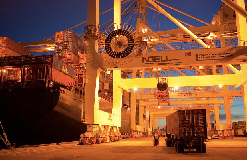
Modern maritime trade across the Middle East relies heavily on uninterrupted efficiency at major logistics hubs such as Jebel Ali Port, Khalifa Port, King Abdulaziz Port in Dammam, and Salalah Port. To keep container ships moving on schedule, heavy equipment like Ship-to-Shore cranes, Rubber-Tyred Gantry cranes, and high-capacity ship loaders operate under demanding schedules. These giant machines do not simply require standard electrical flexibility; they demand cables engineered to survive extreme dynamic forces, relentless high-speed reeling cycles, severe torsional twisting, and intense thermal conditions.
Operating along the Arabian Gulf, the Red Sea, and the Gulf of Oman exposes cabling infrastructure to harsh environmental challenges. Summer temperatures routinely exceed 45 ℃ to 50 ℃, direct solar UV radiation bakes steel reels to even higher temperatures, salt-laden marine air promotes chemical corrosion, and airborne desert sand creates continuous surface friction. Under these conditions, running heavy crane equipment at high speeds can quickly destroy standard flexible cables, leading to outer jacket cracking, core deformation, phase-to-phase electrical short circuits, and unscheduled terminal downtime.
The R-(N)TSCGEWOEU flexible reeling cable provides a robust solution for high-speed dynamic duty. Engineered with reduced structural dimensions and high dynamic strength, this special medium-voltage cable handles high reeling speeds, intense torsional forces, and repeated reverse bending. Its heavy-duty design is also proven in demanding open-cast mining applications—powering excavators, dumpers, and mobile stone crushers—demonstrating its mechanical reliability for port crane electrification.
What Makes R-(N)TSCGEWOEU Different?
The letter "R" in the R-(N)TSCGEWOEU designation signifies a reinforced design specifically built for rapid reeling duty. While standard flexible reeling cables perform well under moderate speeds and predictable linear motion, rapid-cycling container cranes present far higher dynamic stresses that require advanced structural reinforcement.
Compared to conventional cable options, the R-(N)TSCGEWOEU design delivers four key engineering advantages:
Higher Reeling Speed Capabilities: Built with lightweight internal materials and tight core lay lengths, the cable stays structurally balanced on high-speed motorized drums without developing internal core displacement or wave-like distortions.
Superior Dynamic Load Endurance: The inner layers, anti-torsion braid, and outer sheath work together to absorb sudden acceleration forces, emergency braking torque, and dynamic tensile loads.
Advanced Resistance to Torsion and Reverse Bending: High-speed travel over guide sheaves, turnover rollers, and monospiral drums subjects cables to continuous axial twisting. The R-type construction uses an embedded synthetic braid to neutralize rotational stress and protect internal conductors.
Reduced Physical Dimensions: By utilizing high-efficiency insulation compounds like specialized EPDM rubber, the cable achieves a smaller outer diameter and lighter overall weight without compromising dielectric strength or mechanical toughness. This compact footprint is ideal for compact spooling drums and limited reel geometry.
This combination of reduced physical dimensions, thermal endurance, and dynamic flexibility makes the R-(N)TSCGEWOEU cable manufactured by brands like Feichun a top-tier choice for STS trolley systems, RTG yard cranes, and high-speed spooling equipment.
Application And Duty Cycle
The R-(N)TSCGEWOEU cable is engineered for dynamic reeling systems operating under heavy mechanical duty, including both monospiral (flat spooling) reels and cylindrical (multi-layer) drums. Its rugged construction performs reliably across wet, dry, humid, or dusty industrial environments, underground and open-cast mining sites, and explosion-risk hazardous areas.
Translating these heavy-duty capabilities into port crane operations highlights why the cable excels on modern quay decks:
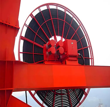
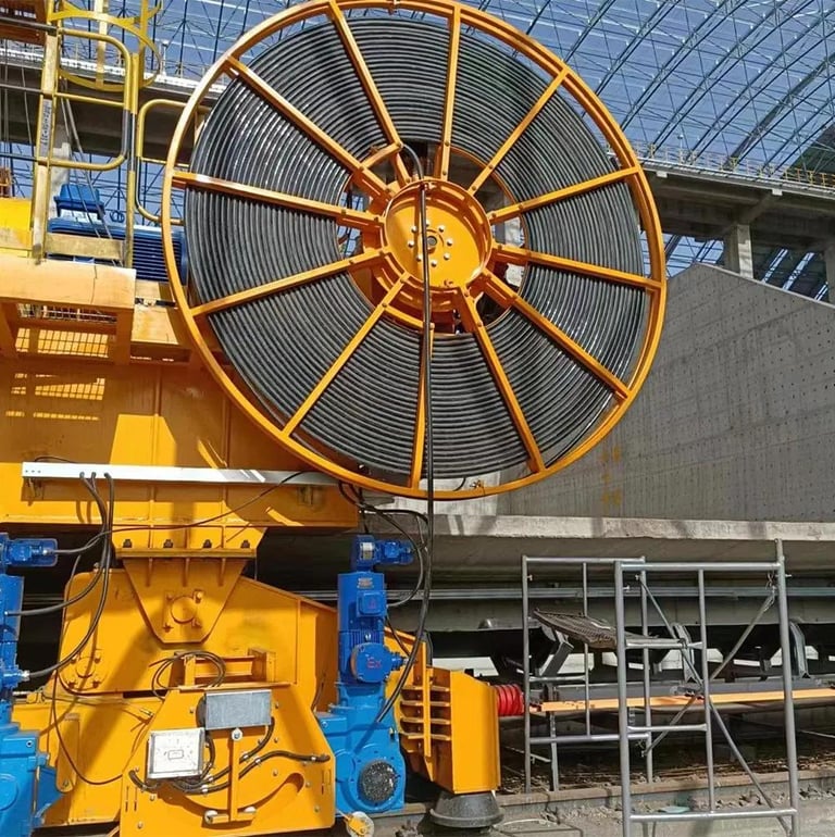
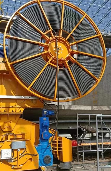
Monospiral Reel Duty: Monospiral drums lay cable in a single flat layer, subjecting the cable to tight bending radii, constant reverse flex cycles, and continuous surface friction as layers wrap over each other. The reduced outer diameter of the R-(N)TSCGEWOEU cable fits neatly into monospiral grooves, minimizing mechanical pinch points and heat buildup.
Cylindrical Reel Duty: Multi-layer cylindrical drums subject lower cable layers to heavy crushing loads and side-wall abrasion. The thermosetting outer rubber jacket and dense internal padding resist flattening and structural core distortion.
Continuous Motion Cycles: Ship-to-Shore cranes and automated stacking gantries run through thousands of acceleration and deceleration cycles every day. The cable's balanced design absorbs constant tension changes, preventing internal component migration and ensuring long service life.
Why Ordinary Cables Fail
Using standard flexible rubber cords or fixed power cables on high-speed crane reels often leads to premature failure. When standard cables are subjected to dynamic reeling, extreme heat, and severe physical stress, they usually suffer from four common structural failures:
COMMON HIGH-SPEED REELING CABLE FAILURES Failure Type Primary Cause ───────────────────────────────────────────────────────────────── Bird-Caging Outer sheath stretches away from internal cores, causing conductors to bunch into open cages. Torsion Damage Unchecked axial twisting breaks internal wires, leading to "corkscrewing" and short circuits. Jacket Cracking UV radiation and extreme ambient heat dry out low-grade rubber, causing surface splits. Conductor Breakage Repetitive bending fatigue snaps copper strands, causing complete phase loss and equipment failure.
Bird-Caging: When a cable is continuously wound under high travel speeds, the outer jacket can stretch at a different rate than the internal power cores. This causes the copper strands to bunch up, creating visible cage-like bulges that jam in guide rollers and ruin the cable.
Torsion Damage and Corkscrewing: As cables pass through reverse-bending guide sheaves across multiple planes, they experience natural rotational torque. If the cable lacks a reinforced anti-torsion braid, this twisting builds up internally until the cores buckle into a corkscrew shape, destroying internal insulation.
Surface Jacket Cracking: Intense Middle Eastern solar UV rays, combined with high ambient heat and airborne salt mist, rapidly age lower-grade rubber compounds. The jacket dries out, hardens, and forms deep cracks that allow water and abrasive silica sand to reach the electrical insulation.
Conductor Breakage from Bending Fatigue: Continuous reverse bending over tight sheaves causes metal fatigue in standard copper strands. Over time, individual copper wires snap, reducing current-carrying capacity, creating localized electrical hot-spots, and ultimately causing catastrophic phase-to-phase short circuits.
In busy container ports, any of these failures causes immediate crane shutdowns, blocks berth schedules, disrupts truck lanes, and results in expensive emergency repairs. Installing specialized high-speed reeling cables eliminates these vulnerabilities, protecting terminal profitability.
Ship-to-Shore Crane Motion Profiles
Ship-to-Shore cranes represent the largest and most vital handling machinery in modern maritime terminals. Operating an STS crane involves complex, simultaneous multi-axis movements that place severe dynamic stress on medium-voltage power cables:
High-Speed Trolley Travel: The trolley moves back and forth along the crane boom at speeds often exceeding 240 meters per minute. Power and control cables spooled on motorized reels must accelerate, run, and decelerate in perfect sync with the trolley, absorbing heavy dynamic tensile loads.
Boom Hoist and Travel Cycles: When a crane raises its boom to clear ship superstructures, feed cables undergo steep angular bends, long vertical suspensions, and elevated mechanical tension.
Motorized Cable Reel Spooling: The main cable reel constantly adjusts torque to pay out and wind in hundreds of meters of heavy medium-voltage cable without letting it slacken into quayside trenches or pulling it too tight.
To handle these combined forces, the R-(N)TSCGEWOEU cable maintains high axial stiffness and longitudinal flexibility, keeping its physical shape stable throughout rapid, repetitive crane motions.
Rubber-Tyred Gantry Crane Requirements
Rubber-Tyred Gantry cranes serve as the backbone of container yard stacking operations. Unlike rail-mounted equipment, RTGs move on heavy rubber tires, transferring between stack blocks, turning across yard corridors, and operating in dynamic container yard layouts.
For electrified RTGs powered via motorized reel systems, cabling requirements are demanding:
High Dynamic Flexibility: RTGs execute frequent short-distance travels, constant directional changes, and high-frequency stops. Cables must flex easily around tight reel drums without developing internal structural memory or stiffness.
Heavy Surface Abrasion Resistance: RTG cables frequently touch concrete yard decks, steel guide troughs, and alignment funnels. Contact with fine desert sand on concrete surfaces acts like sandpaper, making an abrasion-resistant outer jacket essential.
Torsion Neutralization during Yard Turning: When an RTG rotates its wheels 90 degrees to change stack lanes, connected reeling cables experience intense rotational torque. The embedded polyamide anti-torsion braid within the R-(N)TSCGEWOEU cable absorbs this rotational stress, preventing internal structural distortion.
Matching these mechanical demands with an R-type high-speed reeling cable ensures reliable yard container handling, reduced cable wear, and lower terminal maintenance costs.
Cable Construction Features
The durability of the R-(N)TSCGEWOEU cable comes from its specialized multi-layer construction, where every component is engineered to deliver mechanical strength, electrical field control, and long-term weather resistance.
R-(N)TSCGEWOEU CROSS-SECTIONAL BUILD .─────────────────────────. / Class 5 Conductor \ . (Tinned / Bare) . / ─────────────────────────────── \ │ Semi-Conductive Tape Separator │ │ Extruded Semi-Conductor Layer │ .───────────. │ Special EPDM Rubber Insulation │ .───────────. / Earth \│ Strippable Insulation Screen │/ Earth \ . Conductor . Thermosetting Inner Sheath (5GM3) . Conductor . \ (Semi-Cond) / \ Polyamide Anti-Torsion Braid / \ (Semi-Cond) / \ / \ Thermosetting Outer Sheath(5GM5)/ \ / ' . . ' ───────────────────────────────── ' . . ' ' . ' ' . '
High-Flexibility Copper Conductors
The main power conductors feature flexible Class 5 stranded copper wires made from annealed tinned or bare electrolytic copper. Fine stranding provides excellent flexibility, while tinning protects individual strands against chemical oxidation caused by ambient heat and humidity.
Semi-Conductive Tape Separator and Conductor Screen
A specialized semi-conductive tape separator is wrapped over the stranded copper conductor, followed by an extruded semi-conductive rubber layer. This creates a perfectly smooth boundary over the stranded wires, distributing electrical stress evenly and eliminating air gaps that could trigger localized partial discharges.
High-Grade EPDM Rubber Insulation
Primary electrical insulation consists of a high-performance Ethylene Propylene Diene Monomer rubber compound. EPDM delivers exceptional dielectric strength, outstanding thermal aging endurance, low moisture absorption, and high dynamic flexibility across extreme operating temperatures.
Strippable Insulation Screen
A specialized semi-conductive strippable layer is extruded over the EPDM insulation. This outer screen provides precise electrical field control while allowing fast, clean cold stripping during field termination, saving labor time and protecting underlying insulation during splicing.
Integrated Earth Conductors
The protective ground system uses Class 5 flexible copper conductors coated with an extruded semi-conductive rubber compound. Positioned symmetrically in the core gaps, these earth conductors balance cable weight, minimize electromagnetic interference, and ensure ground continuity.
Integrated Fiber Optic Module
For applications requiring simultaneous power and data transmission, an optional A-D(ZN)13Y fiber optic module can be integrated into the core assembly. Available with 6, 12, 18, or 24 individual glass fibers in G50/125 µm, G62.5/125 µm, or E9/125 µm configurations, this module supports real-time telemetry, remote control signals, and condition monitoring without requiring a separate communication cable.
Multi-Layer Protective Sheath Architecture
The sheathing architecture uses a multi-layer design to maximize strength and weather protection:
Inner Sheath: A special synthetic thermosetting compound (type 5GM3 under VDE norms) forms a protective inner cushion, sealing internal components against moisture and absorbing dynamic impacts.
Anti-Torsion Braid: A high-strength reinforcement braid woven from polyamide threads is embedded directly between the inner and outer rubber sheaths. This braided layer converts axial twisting forces into longitudinal stability, preventing structural corkscrewing during high-speed reeling.
Outer Sheath: The exterior jacket is extruded from a heavy-duty thermosetting synthetic rubber compound (type 5GM5) in a bright red finish. It delivers exceptional resistance to physical abrasion, tearing, surface impact, solar UV radiation, ozone, moisture, and industrial oils.
Voltage And Temperature Ratings
The R-(N)TSCGEWOEU cable family is manufactured across four standardized medium-voltage classes, allowing port engineers and OEM specifiers to match exact electrical requirements:
ELECTRICAL VOLTAGE SPECIFICATIONS Rated Voltage Class (Uo/U) Maximum Permissible Voltage AC Test Voltage ───────────────────────────────────────────────────────────────────────────── 3.6/6 (7.2) kV 7.2 kV 11 kV 6/10 (12) kV 12 kV 17 kV 8.7/15 (18) kV 18 kV 24 kV 12/20 (24) kV 24 kV 29 kV
High Thermal Operating Thresholds
Temperature ratings are optimized for demanding industrial duty and high ambient temperature environments:
Maximum Conductor Operating Temperature: +90 ℃ continuously under full electrical load.
Maximum Short-Circuit Conductor Temperature: +250 ℃ for emergency short-circuit durations up to 5 seconds.
Minimum Ambient Temperature for Fixed Installations: -40 ℃.
Minimum Ambient Temperature for Mobile Reeling Installations: -25 ℃.
Operating in Middle Eastern ports—where summer air temperatures reach 45 ℃ to 50 ℃ and radiant solar heat drives steel reel surfaces even higher—requires a continuous +90 ℃ conductor rating. This high thermal threshold provides an essential thermal safety buffer during continuous heavy crane operations.
Key Dimensional Parameters by Voltage Class
The R-(N)TSCGEWOEU design features reduced physical dimensions compared to traditional heavy-duty rubber cables, keeping outer diameters compact and overall weights manageable.
The following dimensional parameters highlight representative conductor sizes across the four standard voltage classes:
3.6/6 (7.2) kV Class
3 x 25 + 25/2 + FO: Nominal conductor diameter 6.5 mm, nominal overall outer diameter 39.9 mm, nominal weight 2479 kg/km, maximum tensile load 1500 N.
3 x 50 + 25/2 + FO: Nominal conductor diameter 9.3 mm, nominal overall outer diameter 45.8 mm, nominal weight 3534 kg/km, maximum tensile load 3000 N.
3 x 95 + 50/2 + FO: Nominal conductor diameter 13.0 mm, nominal overall outer diameter 55.6 mm, nominal weight 5689 kg/km, maximum tensile load 5700 N.
3 x 150 + 70/2 + FO: Nominal conductor diameter 16.2 mm, nominal overall outer diameter 64.3 mm, nominal weight 8259 kg/km, maximum tensile load 9000 N.
3 x 185 + 95/2 + FO: Nominal conductor diameter 18.3 mm, nominal overall outer diameter 68.8 mm, nominal weight 9624 kg/km, maximum tensile load 11100 N.
6/10 (12) kV Class
3 x 25 + 25/2 + FO: Nominal conductor diameter 6.5 mm, nominal overall outer diameter 41.6 mm, nominal weight 2624 kg/km, maximum tensile load 1500 N.
3 x 50 + 25/2 + FO: Nominal conductor diameter 9.3 mm, nominal overall outer diameter 47.5 mm, nominal weight 3699 kg/km, maximum tensile load 3000 N.
3 x 95 + 50/2 + FO: Nominal conductor diameter 13.0 mm, nominal overall outer diameter 57.3 mm, nominal weight 5890 kg/km, maximum tensile load 5700 N.
3 x 150 + 70/2 + FO: Nominal conductor diameter 16.2 mm, nominal overall outer diameter 66.0 mm, nominal weight 8490 kg/km, maximum tensile load 9000 N.
3 x 185 + 95/2 + FO: Nominal conductor diameter 18.3 mm, nominal overall outer diameter 70.5 mm, nominal weight 9871 kg/km, maximum tensile load 11100 N.
8.7/15 (18) kV Class
3 x 25 + 25/2 + FO: Nominal conductor diameter 6.5 mm, nominal overall outer diameter 45.1 mm, nominal weight 2933 kg/km, maximum tensile load 1500 N.
3 x 50 + 25/2 + FO: Nominal conductor diameter 9.3 mm, nominal overall outer diameter 52.7 mm, nominal weight 4270 kg/km, maximum tensile load 3000 N.
3 x 95 + 50/2 + FO: Nominal conductor diameter 13.0 mm, nominal overall outer diameter 60.7 mm, nominal weight 6309 kg/km, maximum tensile load 5700 N.
3 x 150 + 70/2 + FO: Nominal conductor diameter 16.2 mm, nominal overall outer diameter 69.4 mm, nominal weight 8971 kg/km, maximum tensile load 9000 N.
3 x 185 + 95/2 + FO: Nominal conductor diameter 18.3 mm, nominal overall outer diameter 75.8 mm, nominal weight 10702 kg/km, maximum tensile load 11100 N.
12/20 (24) kV Class
3 x 25 + 25/2 + FO: Nominal conductor diameter 6.5 mm, nominal overall outer diameter 48.1 mm, nominal weight 3229 kg/km, maximum tensile load 1500 N.
3 x 50 + 25/2 + FO: Nominal conductor diameter 9.3 mm, nominal overall outer diameter 55.7 mm, nominal weight 4600 kg/km, maximum tensile load 3000 N.
3 x 95 + 50/2 + FO: Nominal conductor diameter 13.0 mm, nominal overall outer diameter 65.6 mm, nominal weight 6961 kg/km, maximum tensile load 5700 N.
3 x 150 + 70/2 + FO: Nominal conductor diameter 16.2 mm, nominal overall outer diameter 72.5 mm, nominal weight 9401 kg/km, maximum tensile load 9000 N.
Critical Mechanical Parameters for Reeling Performance
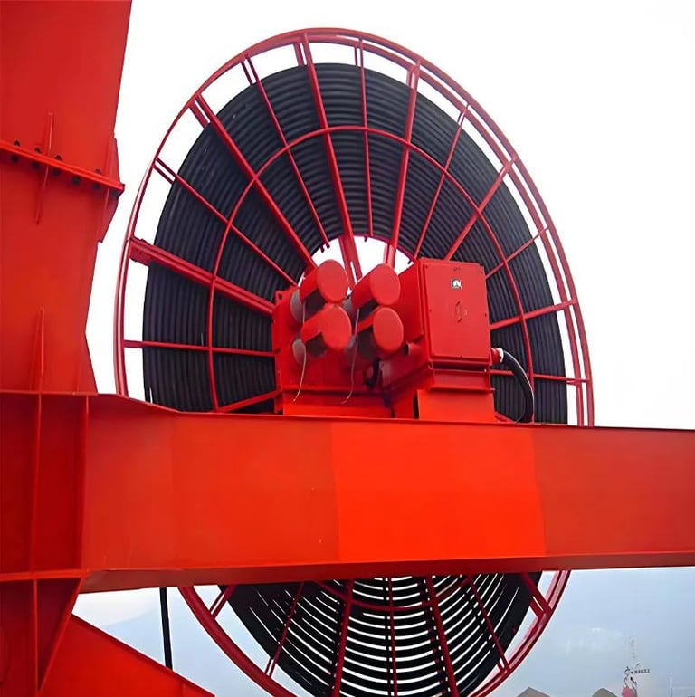
Selecting the right high-speed reeling cable requires verifying mechanical ratings against specific drum geometry and speed profiles. The R-(N)TSCGEWOEU design is engineered to meet demanding mechanical benchmarks:
CRITICAL MECHANICAL PERFORMANCE VALUES Mechanical Metric Design Benchmark Specification ───────────────────────────────────────────────────────────────────────── Minimum Dynamic Bending Radius 6 × Outer Cable Diameter (6 × D) Maximum Continuous Tensile Load 20 N per mm² copper cross-section Peak Acceleration Tensile Load Up to 30 N per mm² copper cross-section Permissible Torsional Stress ±25 degrees per meter (±25 °/m) Gantry Travel Speeds Beyond 240 m/min (consult Feichun)
Ultra-Tight Minimum Bending Radius
With a minimum dynamic bending radius of just 6 times the outer cable diameter (6 × D), the R-(N)TSCGEWOEU cable flexes easily around compact spooling barrels, small guide sheaves, and tight turnover assemblies without causing internal structural fatigue or insulation damage.
Dynamic Tensile Load Capacities
During standard spooling operations, maximum continuous pulling tension should not exceed 20 N per square millimeter of total copper cross-section. During rapid acceleration, braking, or sudden directional changes, the cable handles dynamic peak tensile loads up to 30 N per square millimeter.
Resistance to Torsional Twist
The embedded polyamide anti-torsion braid allows the cable to withstand severe axial twisting up to plus or minus 25 degrees per meter (±25 °/m). This prevents structural corkscrewing and internal core displacement during high-speed multi-plane travel.
High Travel Speed Compatibility
The R-(N)TSCGEWOEU cable is engineered for fast travel speeds. For ultra-high-speed machinery operating beyond 240 meters per minute, engineering consultation with Feichun is recommended to optimize drum control, motor torque settings, and guide sheave spacing.
Why Reeling Speed Matters
As modern container terminals increase travel speeds to accelerate ship turnover, cable reels experience significantly higher mechanical stress. High reeling speeds create physical forces that accelerate wear on standard cables:
MECHANICAL IMPACTS OF HIGH REELING SPEEDS [ High Travel Speed ] ───> Elevated Friction & Internal Heat Higher Dynamic Tensile Spikes Increased Flexing Fatigue Cycles Amplified Axial Torsional Torque
Friction and Thermal Build-up: Rapid winding and unwinding on monospiral drums creates heavy surface friction and internal heat. Without high-performance EPDM insulation and thermosetting rubber sheaths, heat accumulation degrades low-grade rubber compounds.
Tensile Spikes During Acceleration: Sudden motor acceleration creates sharp tensile load spikes. Standard cables can stretch under these loads, causing internal core displacement.
High Flexing Fatigue: High travel speeds subject cables to thousands of reverse bending cycles per hour over guide rollers, leading to metal fatigue in copper conductors.
Rotational Torque Amplification: Fast movement across guide sheaves amplifies axial twisting forces, rapidly degrading cables that lack specialized anti-torsion braiding.
Selecting a purpose-built high-speed reeling cable engineered for rapid motion ensures that travel speed increases translate into higher port productivity rather than unexpected downtime.
Fiber Optics for Advanced Crane Systems
Modern smart container terminals require simultaneous medium-voltage power delivery and real-time data communication. Incorporating an optional A-D(ZN)13Y fiber optic module within the R-(N)TSCGEWOEU cable core provides an integrated power and optical data transmission solution.
INTEGRATED FIBER OPTIC CABLE ARCHITECTURE ┌─────────────────────────────────────────────────────────────────┐ │ Fiber Module Type: A-D(ZN)13Y with 6, 12, 18, or 24 Fibers │ ├─────────────────────────────────────────────────────────────────┤ │ Multimode G50/125 µm & G62.5/125 µm for Local Control Networks │ ├─────────────────────────────────────────────────────────────────┤ │ Monomode E9/125 µm for Long-Distance High-Speed Data Links │ └─────────────────────────────────────────────────────────────────┘
Integrating fiber optics directly into the power cable offers key technical advantages for terminal automation:
Multi-Channel Data Transmission: Supports 6, 12, 18, or 24 individual optical glass fibers, accommodating extensive network topologies within a single cable.
Multimode and Monomode Options: Multimode fibers (G50/125 µm and G62.5/125 µm) support short-to-medium distance control networks, while monomode fibers (E9/125 µm) enable long-distance signal transmission to central operations desks without signal repeaters.
Complete Immunity to Electrical Noise: Optical signals traveling through glass fibers are completely immune to electromagnetic fields and variable frequency drive noise, ensuring stable data transmission alongside high-voltage power lines.
Essential Support for Smart Port Technologies: Provides the reliable data backbone needed for high-definition video camera feeds, laser spreader positioning systems, remote joystick control, and predictive health sensors.
For a comprehensive analysis of optical fiber construction techniques, gel-filled buffer tube designs, and splicing procedures for dynamic marine equipment, explore our separate technical guide on specialized fiber optic cables for industrial applications.
Where It Fits In Port Cranes and Heavy Equipment
The combination of reduced outer dimensions, high dynamic tensile capacity, severe torsion protection, and optional fiber optic integration makes R-(N)TSCGEWOEU cables an ideal choice for high-stress port and industrial equipment:
Ship-to-Shore (STS) Cranes: Supplies reliable power and continuous data links to fast-moving trolleys, boom hoist drives, and main gantry travel reels operating on monospiral drums.
Rubber-Tyred Gantry (RTG) Cranes: Delivers flexible power to yard container stackers, resisting severe ground abrasion, solar UV rays, and rotational torque during 90-degree wheel turns.
Continuous Ship Unloaders and Bulk Loaders: Powers long-travel bulk material handling equipment operating under heavy dust, high vibration, and continuous outdoor exposure.
Heavy Open-Cast Mining Machinery: Powers large excavators, mobile crushers, and haulage dumpers in open-cast mines, proving its mechanical durability in severe industrial environments.
Selection Checklist For Buyers
When procuring high-speed medium-voltage reeling cables for Middle Eastern port projects, engineering teams should evaluate technical submittals against this checklist:
Confirm Reel Type and Geometry: Verify whether the installation uses monospiral reels or multi-layer cylindrical drums, ensuring drum barrel diameters meet or exceed the 6 × D minimum bending radius requirement.
Validate Travel Speeds and Acceleration Curves: Confirm maximum travel speeds and acceleration profiles[cite: 2]. For travel speeds exceeding 240 m/min, consult Feichun to verify reel torque settings and tension control.
Calculate Dynamic Pulling Tension: Calculate peak dynamic pulling forces during startup and braking to ensure loads remain within the 20 N/mm² continuous (or 30 N/mm² peak) limits for the selected copper cross-section.
Check Space Constraints and Cable Weight: Review available spooling reel width and guide funnel dimensions, selecting compact cable diameters to minimize total drum weight and reel inertia.
Determine Optical Communication Needs: Identify the required fiber count (6, 12, 18, or 24) and glass fiber type (multimode or monomode) for control, video, and monitoring systems.
Verify Environmental Resistance Compounds: Confirm that the outer sheath compound (type 5GM5) includes UV and ozone stabilization for high ambient heat, salt fog resistance, and oil resistance per DIN EN 60811-404 standards.
Recommended Visual Documentation Elements
To complement technical submittals, blog articles, or engineering proposals, consider incorporating these visual elements:
STS Crane Motorized Reel Layout: A technical illustration showing a high-speed monospiral reel, turnover sheaves, and cable routing along a quayside trench.
RTG Yard Crane Cable Spooling Diagram: A diagram illustrating an electrified RTG moving along container stacks with an active reeling system.
Cable Drum and Sheave Geometry Close-Up: An annotated schematic showing cable wrap patterns, minimum bending radii over guide rollers, and anti-torsion braid performance.
Conclusion
Operating container terminals in the Middle East requires high equipment reliability under challenging environmental conditions. Standard flexible cables are simply not built to handle the combination of high travel speeds, continuous reverse bending, severe torsional torque, intense UV exposure, and ambient summer heat.
The R-(N)TSCGEWOEU flexible reeling cable provides a purpose-built solution for dynamic crane duty[cite: 2]. Featuring a compact cross-section, flexible Class 5 tinned copper conductors, high-grade EPDM rubber insulation, an embedded polyamide anti-torsion braid, a heavy-duty thermosetting outer sheath, and an optional integrated fiber optic module, it delivers reliable medium-voltage power and data transmission under high mechanical stress.
By choosing R-(N)TSCGEWOEU cables manufactured by Feichun, port operators can minimize cable failures, lower maintenance costs, and keep container handling operations running smoothly.
Would you like me to generate a technical datasheet submittal or calculate thermal ampacity derating values for this cable based on your target Middle Eastern port's maximum ambient summer temperatures?
Port crane cables | Mining cables | Reeling cables | Trailing cables | Festoon cables | Heavy-duty power cables | Medium voltage cables | Offshore crane cables | Underground mining cables | Dragline cables | Shearer cables | Container handling cables | STS crane cables | RTG cables | Mobile equipment cables | Armored cables | Flexible power cables | VFD cables | Submersible cables | Cold resistant cables | Abrasion resistant cables | Flame retardant cables | Marine environment cables | Opencast mining | Underground operations
© 2006 All rights reserved.
[INDUSTRIAL_CABLES]
INDUSTRIAL GRADE CABLE SYSTEMS | PORT & MINING SOLUTIONS
TEL: +86 153 7530 2641 |MAIL: hongjing.Wang@feichuncables.com