How Jebel Ali Port and Bowen Basin Coal Mines Rely on (N)TMCGCW11Y Medium Voltage Cables to Power Critical Operations
Learn how the high-flexible medium voltage screened single-core cable (N)TMCGCW11Y powers crane systems at Jebel Ali Port and mining fleets in Australia's Bowen Basin — covering design specs, electrical ratings, mechanical performance, and real-world deployment insights under DIN VDE 0250-813.
hongjing.Wang@Feichun
3/27/202619 min read

What Is the (N)TMCGCW11Y Cable? (Google Featured Snippet)
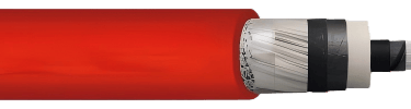
The (N)TMCGCW11Y is a high-flexible, medium voltage, screened single-core rubber-insulated cable with a thermoplastic polyurethane (PUR) outer sheath, designed and tested in accordance with DIN VDE 0250-813. It is engineered for dynamic industrial environments — including port crane systems, offshore shore power infrastructure, and underground or open-pit mining operations — where cables must endure repetitive bending, mechanical impact, wide temperature swings, and continuous movement. Rated voltages range from 3.6/6 kV up to 18/30 kV, with a maximum conductor operating temperature of 90 °C and a short-circuit withstand temperature of 200 °C. The cable features finely stranded tinned copper conductors (Class 5, IEC 60228), EPR insulation with inner and outer semi-conductive layers, a concentric tinned copper ground conductor, steel wire braid reinforcement, and a halogen-free, flame-retardant red PUR outer sheath.
1. Introduction: Built for the World's Harshest Industrial Environments
Port terminals and mining operations share a common engineering challenge: they demand reliable, uninterrupted electrical power in conditions that would rapidly destroy ordinary cables. Gantry cranes lift and reposition thousands of containers per day. Draglines in coal mines operate around the clock across open-pit faces spanning several kilometres. Shore power systems must connect and disconnect from vessels dozens of times per shift.
In these environments, cable failure is never just a maintenance inconvenience — it translates directly into halted production, compromised safety, and cascading financial loss. The (N)TMCGCW11Y medium voltage cable was developed precisely to address this reality, combining mechanical robustness, superior electrical performance, and environmental resistance in a single-core design that engineers can specify with confidence for dynamic installations.
This article examines the technical foundations of the cable, illustrates its specifications in practical terms, and walks through how it performs in two representative real-world deployments: the container terminal at Jebel Ali Port, Dubai (UAE), and longwall and open-cut mining equipment at the Bowen Basin coalfields in Queensland, Australia.
2. Standards Compliance: The Engineering Foundation
The (N)TMCGCW11Y is designed, constructed, and tested against a robust framework of international and European standards. Understanding which standards apply — and why — is essential for engineers evaluating cable suitability for specific project classifications.
DIN VDE 0250-813 governs the overall design and type-testing requirements for flexible medium voltage cables intended for industrial and mining applications. Compliance with this standard confirms that the cable has been validated for electrical withstand, mechanical durability, and thermal performance under representative service conditions.
DIN EN / IEC 60228 defines the conductor class. Class 5 conductors, used in this cable, are the most finely stranded category, which directly correlates to the cable's outstanding flexibility and resistance to fatigue from repeated bending cycles.
EN 50363-10-2 covers the thermoplastic polyether-based PUR outer sheath system, ensuring defined performance in terms of mechanical properties, temperature resistance, and chemical compatibility.
EN 60332-1-2 defines the flame propagation behaviour of a single vertically mounted cable subjected to a defined flame source. Meeting this standard is a basic prerequisite for safe routing in enclosed structures such as cable ducts, crane masts, and switchgear rooms.
EN 60811-404 specifies the method for testing oil resistance of insulation and sheath materials — a critical parameter in both port machine rooms and mining environments where hydraulic fluids and lubricants are present.
EN 60754-1 quantifies the amount of halogen acid gas released during combustion. Low halogen acid gas emission reduces corrosive damage to sensitive electrical equipment and lowers the risk of toxic exposure for personnel trapped in an area during a fire event.
Together, these standards provide a comprehensive quality assurance framework covering electrical safety, fire performance, mechanical robustness, chemical resistance, and environmental suitability for long service life in demanding industrial settings.
3. Electrical Characteristics: Voltage Classes and System Compatibility
One of the most important design decisions for any medium voltage cable project is selecting the correct voltage class. The (N)TMCGCW11Y is available across six rated voltage levels:
3.6/6 kV — suited to smaller distribution networks and equipment with relatively modest current demands, commonly found in older port auxiliary systems or light-duty mining plant.
6/10 kV — a very widely used industrial voltage class, covering the majority of modern port crane feeder systems and medium-scale mining equipment.
8.7/15 kV — common in European and Australian mining networks, particularly for feeder cables to large electric shovel and dragline systems.
12/20 kV — increasingly used in large port infrastructure and offshore wind O&M vessels where distribution efficiency at higher voltage reduces cable cross-section and associated weight.
14/25 kV — less common but important for large open-pit mining fleets and some Middle Eastern industrial distribution systems operating at non-standard voltage levels.
18/30 kV — the highest class in the range, applicable to power supply for very large mining drives, high-capacity shore power terminals, and offshore platform main feeders.
In AC systems, the maximum permissible operating voltage is 15% above the rated phase-to-earth voltage, and AC test voltages according to DIN VDE 0250-813 confirm dielectric integrity across the full service life. For DC applications — increasingly relevant as shore power technology moves toward DC grid architectures — the cable supports maximum operating voltages approximately double the AC values at equivalent rated classes.
The maximum permissible conductor temperature in normal continuous operation is 90 °C, which governs current carrying capacity according to IEC 60364-5-52. Under short-circuit conditions, the conductor may reach 200 °C for a brief period without permanent damage to the insulation system — a safety margin that ensures the cable survives fault clearance events that would otherwise cause immediate insulation breakdown in lesser designs.
4. Thermal Performance: From Arctic Laydown Yards to Qatari Summer Heat
Temperature range is a defining characteristic of any flexible industrial cable. The (N)TMCGCW11Y supports:
Fixed installation: -50 °C to +90 °C ambient temperature range. This extraordinary cold-weather capability makes the cable suitable for installations in northern Canadian mining sites, Norwegian offshore terminals, and Siberian industrial plants, where equipment must remain operational through extreme winter conditions without any risk of insulation embrittlement or cracking.
Flexible operation: -40 °C to +90 °C. Even when the cable is being continuously moved, bent, and flexed, it retains its mechanical integrity and electrical performance at temperatures that would cause many competitive materials to become dangerously brittle.
At the upper end, the +90 °C ambient rating is significant for Middle Eastern port environments such as Jebel Ali, where cable management surfaces inside crane structures can reach extreme temperatures under direct summer sunlight. Cables that are only rated to +70 °C ambient may require uprating, derating, or additional thermal protection measures — adding cost and complexity that the (N)TMCGCW11Y eliminates.
The EPR (Ethylene Propylene Rubber) insulation system is inherently superior to XLPE for high-temperature applications because it maintains flexibility across a wider temperature range and resists thermal ageing and oxidation more effectively over multi-decade service lives. The outer PUR sheath complements this by providing surface protection against the UV radiation, ozone, and moisture that EPR insulation alone would not resist adequately.
5. Mechanical Properties and Flexibility: Engineering for Continuous Motion
The mechanical specification of the (N)TMCGCW11Y reflects a cable designed not merely for occasional repositioning but for continuous, high-cycle dynamic service.
The maximum permissible tensile load is 15 N/mm² of conductor cross-section. For a 1×95 mm² cable, this means the cable can sustain a sustained tensile force of approximately 1,425 N before reaching the design limit — providing ample margin for the dynamic loads introduced by crane boom movements and cable reel acceleration.
Bending radius requirements define how tightly a cable can be wound or turned without fatigue damage accumulating at the bend point:
Fixed installation: ≥ 6 × outer diameter. For a cable with an outer diameter of, say, 32 mm, this means the absolute minimum static bend radius is 192 mm. In practice, fixed installations are designed with larger radii for longevity.
Free moving (dynamic): ≥ 8 × outer diameter. The same cable in a moving application would require a minimum radius of 256 mm. Energy chain systems and cable reels must be engineered to honour this requirement across all operating positions, including at the fully extended and fully retracted positions of the chain or reel.
Movement speed capabilities are a critical parameter for energy chain and reel system designers:
Shore power systems: approximately 6 m/min. Shore power cable management systems connect and disconnect large flexible cable assemblies from berthed container vessels. The relatively low movement speed reflects the weight of the cable assemblies and the controlled nature of the connection process, but it also demands cables that can be reliably handled by automated tensioning systems without kinking or jacket damage.
Energy chains on cranes: 70 to 240 m/min. This is an extremely demanding specification. At 240 m/min — equivalent to 4 metres per second — the cable must withstand the acceleration and deceleration forces generated each time the crane trolley reverses direction, multiplied by the thousands of cycles completed in a single working day.
The Class 5 finely stranded tinned copper conductor construction, the flexible EPR insulation, and the concentric tinned copper protective conductor together create a cable assembly that distributes bending stress uniformly across thousands of individual wire strands rather than concentrating it in a small number of solid conductors. This is what enables the cable to survive millions of bending cycles without conductor wire fatigue failure.

6. Cable Construction and Materials: Layers That Work Together
Understanding the function of each layer in the cable construction helps engineers appreciate why specifications are set as they are and how they interact in service.
Conductor — Tinned copper, Class 5, DIN EN/IEC 60228. Fine stranding means more individual wires of smaller diameter bundled together. Each wire bends more easily than a thicker strand, and the friction between wires in the bundle allows the assembly to flex repeatedly without fatigue cracks initiating at wire surfaces. Tinning protects the copper surface from oxidation, which is particularly important in the presence of ozone, moisture, and chemically active environments.
Inner semi-conductive stress control layer. This thin semi-conductive rubber layer sits immediately over the conductor and eliminates the air voids that would otherwise form between the irregular conductor surface and the insulation. Without this layer, partial discharge would initiate in those voids and progressively destroy the insulation from the inside out. The stress control layer ensures a smooth, equipotential interface between conductor and insulation.
EPR insulation — DIN VDE 0207-20. Ethylene Propylene Rubber with improved electrical and mechanical characteristics provides the primary dielectric barrier. EPR's molecular structure makes it inherently resistant to water treeing — a degradation mechanism that causes premature failure in XLPE cables exposed to water ingress — making it the preferred insulation material for outdoor and submerged medium voltage cable applications.
Outer semi-conductive insulation shield layer. Placed over the insulation, this layer performs the mirror function of the inner layer: it provides a smooth interface between insulation and ground conductor, preventing partial discharge from initiating at the insulation outer surface.
Concentric ground conductor — Tinned copper wire strands, approx. 85% coverage, DIN VDE 0250-1. The concentric ground conductor fulfils two essential functions simultaneously. First, it provides a low-impedance return path for fault current, enabling protective devices to clear ground faults rapidly and reliably. Second, its uniform distribution around the insulated core creates an electrostatic shield that confines the electric field within the cable — reducing electromagnetic interference emitted by the cable and protecting the cable from external interference sources.
Steel wire braid reinforcement. Braided over the ground conductor assembly, the steel wire braid dramatically increases the cable's resistance to crushing, abrasion, impact, and torsional forces. In crane applications where cable may be dragged across steel cable guide surfaces, or in mining environments where rock fragments may contact the cable, this layer provides a first line of mechanical defence.
Outer sheath — Thermoplastic polyether-based PUR, red, EN 50363-10-2. Polyether-based PUR combines properties that no other single sheath material matches: exceptional abrasion resistance, high flexibility even at low temperatures, resistance to hydrolysis (degradation by moisture over time), resistance to oils and fuels, UV stability, ozone resistance, and halogen-free combustion characteristics. The red colour provides immediate visual identification and assists with safety inspection. Inkjet marking enables traceability throughout the cable's service life.
7. Screening, Grounding, and Electromagnetic Compatibility
In medium voltage systems, unscreened single-core cables present significant electromagnetic interference risks and unsafe touch voltages on adjacent metalwork. The concentric ground conductor of the (N)TMCGCW11Y provides continuous 360° electrostatic shielding along the full cable length.
The approximately 85% coverage of the concentric ground conductor represents a carefully balanced engineering choice. Higher coverage improves shielding effectiveness but adds weight and reduces flexibility. The 85% figure provides effective screening performance — reducing capacitively coupled interference to acceptable levels — while retaining the cable flexibility necessary for energy chain and reel applications.
In crane systems where multiple single-core cables are routed in close proximity, effective screening prevents capacitive coupling between phases, which would otherwise cause interference in control and measurement circuits running in the same cable tray. This is particularly important for the precise positioning control systems used in automated container terminals, where inaccurate load position data caused by electrical interference could result in operational errors.
For shore power systems, where the cable passes through the hull penetration of a vessel and connects to the ship's main switchboard, electromagnetic compatibility requirements are often specified by the classification society. The screened design of the (N)TMCGCW11Y supports compliance with these requirements without additional screening measures.
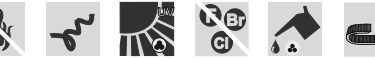
8. Fire, Safety, and Environmental Resistance
Halogen-free construction. Both the PUR outer sheath and the internal compound materials are selected to ensure that the cable does not release significant concentrations of hydrogen chloride or other halogen acid gases when burned. According to EN 60754-1 testing, the halogen acid gas content falls within safe limits. This matters enormously in confined spaces — crane operator cabs, switchgear rooms, ship engine rooms, and mining machine operator compartments — where personnel may not be able to immediately evacuate during a fire event.
Flame retardancy — EN 60332-1-2. The cable resists sustained flame propagation when subjected to a defined test flame. This does not mean the cable is fireproof — no polymer-based cable is — but it does mean that a localised fire will not use the cable as a propagation pathway to spread beyond its point of origin. In long cable runs on crane structures or in cable management trays, this characteristic is critical to preventing a small electrical fault from escalating into a catastrophic fire.
UV and ozone resistance. Both the PUR sheath and EPR insulation system are formulated to resist surface degradation from prolonged ultraviolet radiation and atmospheric ozone. This is directly relevant to cables installed on outdoor crane structures in sunny, coastal environments such as Jebel Ali, where UV exposure is intense and salt-laden sea air accelerates ozone generation.
Oil resistance — EN 60811-404. Tested and confirmed to resist swelling, softening, or mechanical degradation when in contact with mineral oils and hydraulic fluids. In crane machine rooms and mining equipment, hydraulic fluid leaks are a routine occurrence, and cables that absorb oil will rapidly develop jacket cracks and become a contamination pathway for moisture ingress to the insulation.
Water submersion resistance. The (N)TMCGCW11Y is rated for use in locations where cables are completely submerged and subjected to continuous water pressure of up to 10 bar — protection class Ad8. For shore power cables in tidal port environments, this rating ensures that cables accidentally submerged during berthing operations are not damaged, maintaining service continuity without emergency replacement.
9. Real-World Application Case Study 1: Jebel Ali Port, Dubai — Shore Power and Crane Energy Chain Systems
Jebel Ali Port in Dubai, operated by DP World, is one of the largest container terminals in the world and the busiest port in the Middle East. The terminal handles millions of TEUs annually across dozens of deep-water berths equipped with Ship-to-Shore (STS) cranes and Automated Stacking Cranes (ASC).
Shore Power Infrastructure at Jebel Ali
As part of sustainability and emissions reduction programmes aligned with the UAE's Net Zero 2050 strategic initiative, Jebel Ali has expanded its shore power (also called cold ironing) infrastructure to allow berthed container vessels to switch off their auxiliary diesel generators and connect to the terminal's electrical grid. This reduces noise, exhaust emissions, and fuel consumption while vessels are loading and unloading.
Shore power at a major container terminal operating at Jebel Ali's scale typically involves medium voltage cable assemblies connecting the quayside distribution point to the vessel's shore connection cabinet. The voltage class for modern large-vessel shore power connections at 50 Hz typically falls in the 6/10 kV or 12/20 kV range.
The (N)TMCGCW11Y at these voltage classes is ideally suited to the Jebel Ali shore power environment for several reasons. The upper ambient temperature rating of +90 °C accommodates the extreme summer heat on the quayside, where cable surface temperatures on exposed cable management equipment can exceed the ambient air temperature significantly. The minimum bending radius of 8 × outer diameter for free-moving applications is compatible with the cable reels and management systems used to deploy and recover shore power cables at each berth. The movement speed of approximately 6 m/min matches the controlled deployment speed of motorised shore power cable reel systems.
The oil resistance of the PUR sheath prevents degradation from hydraulic fluid contamination common in the quay crane machine rooms through which cable routing may pass. The water submersion rating to 10 bar ensures that cables accidentally submerged when a berth is flooded during storm surges or maintenance operations remain serviceable without requiring replacement.
The halogen-free, flame-retardant characteristics are particularly important in the confined spaces of vessel engine rooms and shore connection cabinet areas, where personnel may be working in close proximity to cable assemblies.
STS Crane Energy Chain Systems at Jebel Ali
The STS gantry cranes at Jebel Ali are equipped with trolley energy chain systems that must carry medium voltage power cables from the fixed boom structure to the moving trolley — a distance that can exceed 60 metres of travel on large post-Panamax cranes. The trolley reverses direction many times per hour during active loading and unloading operations.
At energy chain speeds of up to 240 m/min, a cable at this installation must be capable of withstanding the full acceleration and deceleration load at every cycle, sustained across a service life measured in years rather than months. The Class 5 fine stranding and the minimum dynamic bending radius of ≥ 8 × outer diameter specification of the (N)TMCGCW11Y directly address this requirement. At a 6/10 kV rated voltage — appropriate for the crane hoist and trolley drive systems — the cable provides sufficient insulation margin with a compact outer diameter that minimises the energy chain's internal space requirements.
The steel wire braid reinforcement protects against abrasion from the energy chain guide tracks, which are exposed to salt air and sand at a coastal port environment. The UV-resistant red PUR sheath remains flexible and visually inspectable throughout the crane's service life, supporting the predictive maintenance programmes that DP World and similar terminal operators use to maximise uptime.
10. Real-World Application Case Study 2: Bowen Basin, Queensland — Mining Equipment Power Supply
The Bowen Basin in central Queensland is Australia's primary metallurgical coal-producing region, containing several of the world's largest coal mines including Goonyella Riverside, Peak Downs, Saraji, and Blackwater. These open-cut operations use electric cable reel systems on draglines, electric shovels, and conveyor drive stations, requiring medium voltage flexible cables capable of sustained dynamic operation in one of the world's most demanding mining environments.
Dragline Cable Reel Systems at Goonyella Riverside
Draglines are among the largest electrical machines ever built. The draglines operating at mines such as Goonyella Riverside in the Bowen Basin are typically powered at 8.7/15 kV or 11 kV (which falls within the 6/10 kV class for Australian grid conventions), supplied via motorised cable reel systems that allow the machine to walk and swing across the mine bench while maintaining continuous power connection.
The cable reel at a large dragline may carry 300 to 500 metres of medium voltage cable, unreeling and recovering the cable as the machine traverses the pit perimeter. The cable must sustain tensile loads from its own weight over extended spans, resist crushing where it contacts the ground, and survive repeated winding and unwinding cycles that impose significant bending fatigue at the reel drum.
The (N)TMCGCW11Y's tensile rating of 15 N/mm² per conductor, combined with the concentric ground conductor and steel wire braid, gives the assembly the mechanical strength to survive the combination of dead weight tension, dynamic impact loads from ground contact, and drum bending cycles. A 1×185/25 mm² or 1×240/25 mm² cross-section at 8.7/15 kV would typically be specified for dragline feeders in this size class, providing the current carrying capacity needed for multi-megawatt machines while remaining manageable on a reel drum of practical diameter.
The minimum bending radius of ≥ 8 × outer diameter for free-moving applications must be respected in the design of the reel drum diameter. For a 1×240/25 cable with an outer diameter in the range of 43–45 mm, this means the reel drum inner diameter must be at least 360 mm — a standard engineering constraint that experienced mining cable reel designers build into their drum specifications.
The -40 °C flexible operation temperature rating is relevant to Bowen Basin operations because Queensland winters, while mild by world standards, can produce overnight minimum temperatures low enough to stiffen inferior cable materials, causing handling damage and increased bending stress during early-morning equipment start-up. The (N)TMCGCW11Y retains its designed flexibility well below any temperature encountered in the Bowen Basin climate.
Electric Shovel Power Supply at Peak Downs
Electric mining shovels at open-cut operations such as Peak Downs receive power through trailing cables that must be managed as the machine moves across the pit bench. The trailing cable lies on the pit floor, is periodically repositioned by dedicated cable handlers, and must resist crushing by bucket loads and running over by support vehicles.
The steel wire braid reinforcement of the (N)TMCGCW11Y provides a first line of defence against crushing forces, while the robust PUR outer sheath resists abrasion from the coarse coal and overburden materials the cable contacts on the pit floor. The oil resistance of the sheath prevents degradation from hydraulic fluid drips from the shovel's hydraulic systems and from the fuel and oil residues common on active mine benches.
At the 6/10 kV or 8.7/15 kV voltage classes relevant to large electric shovels in the Bowen Basin, the cable provides reliable power supply while the screened construction ensures electromagnetic compatibility with the mine's communications and control systems — increasingly important as mines adopt automated dispatch, GPS tracking, and remote monitoring systems that rely on radio frequency communications that can be disrupted by poorly screened power cables.
11. Selection Considerations for System Designers
Selecting the correct (N)TMCGCW11Y configuration for a specific project requires evaluation of several interdependent parameters:
Voltage class selection must be based on the system operating voltage, including consideration of the 15% overvoltage margin for AC systems. Selecting one voltage class higher than strictly required by the operating voltage provides an additional safety margin in systems with poor voltage regulation.
Cross-section selection is governed by current carrying capacity requirements, which depend on the load current, ambient temperature, installation method, and grouping of cables in the same conduit or tray. The reference values in the datasheet are based on IEC 60364-5-52, installation method F (free in air), trefoil arrangement, at 30 °C ambient temperature. Projects with different installation conditions must apply the appropriate derating factors from DIN VDE 0298-4.
Bending radius and energy chain geometry must be designed together. The energy chain manufacturer and the cable supplier need to agree on the energy chain's internal bend radius, filling factor, and separation requirements before the system is finalised. An energy chain designed without confirming cable compatibility may impose bending radii smaller than the cable minimum, dramatically shortening cable service life.
Movement speed in the energy chain must be confirmed to be within the cable's mechanical capability. While the datasheet lists 70–240 m/min as a typical range for crane energy chains, specific applications should be reviewed against the cable supplier's detailed application data.
Environmental factor checklist: UV exposure level; presence of oils, fuels, or chemicals; ambient temperature range at both installation and operation phases; water exposure risk and pressure; wind load on exposed cable sections; and the fire resistance classification required by the applicable building or facility code.
Ground fault protection coordination. In screened medium voltage systems, the ground conductor impedance must be evaluated against the protection relay settings to confirm rapid fault clearance. The concentric ground conductor coverage and cross-section must be confirmed as adequate for the maximum prospective ground fault current.
12. Summary of Key Benefits
The (N)TMCGCW11Y medium voltage cable delivers a comprehensive performance package for demanding crane, port, mining, and offshore applications:
High flexibility from Class 5 fine-stranded tinned copper conductors and EPR insulation supports continuous dynamic operation in energy chains and cable reels without fatigue failure.
Wide temperature range from -50 °C (fixed) or -40 °C (flexible) to +90 °C makes it suitable for both arctic and desert industrial environments without special thermal management measures.
Robust mechanical construction with steel wire braid reinforcement provides resistance to crushing, abrasion, impact, and torsion in the most demanding port and mining environments.
Effective screening and grounding through the 85% coverage concentric tinned copper conductor ensures electromagnetic compatibility and safe fault clearance in screened medium voltage networks.
Fire and environmental safety through halogen-free PUR sheath, EN 60332-1-2 flame retardancy, oil resistance, UV resistance, ozone resistance, and Ad8 water submersion rating delivers long service life in corrosive, wet, and contaminated environments.
Broad voltage class range from 3.6/6 kV to 18/30 kV accommodates the full spectrum of industrial and port medium voltage distribution systems without requiring different cable families for different parts of the same installation.
Engineers and project planners specifying medium voltage cables for new port infrastructure, crane upgrades, mining equipment procurement, or shore power installations should evaluate the (N)TMCGCW11Y as a primary candidate wherever high flexibility, mechanical durability, and broad environmental resistance are required simultaneously.
FAQ: (N)TMCGCW11Y Medium Voltage Cable — Common Questions Answered
Q: What does the designation (N)TMCGCW11Y stand for? A: The designation follows the German cable coding system under DIN VDE standards. Key elements include: (N) indicating a harmonised or national standard type; T for thermoplastic or rubber-based insulation depending on position; M for mining/industrial application; C indicating copper conductor; G for rubber (Gummi) insulation; C for concentric ground conductor; W for steel wire braid; 1 and 1 for specific construction codes; and Y for polyurethane outer sheath.
Q: What is the rated voltage range of the (N)TMCGCW11Y? A: The cable is available in six voltage classes: 3.6/6 kV, 6/10 kV, 8.7/15 kV, 12/20 kV, 14/25 kV, and 18/30 kV. The notation follows the convention of phase-to-earth voltage (U₀) / phase-to-phase voltage (U).
Q: How many bending cycles can the cable withstand? A: The cable is designed for continuous dynamic operation typical of industrial energy chain and cable reel applications. Specific bending cycle life data depends on the actual bend radius, movement speed, and ambient temperature, and should be confirmed with the manufacturer for the specific application parameters. The design standards require proven performance under representative test conditions.
Q: Can the (N)TMCGCW11Y be used for DC shore power systems? A: Yes. The cable is rated for DC systems, with the maximum permissible DC operating voltage approximately double the equivalent AC rating at each voltage class — for example, 9/18 kV DC at the 3.6/6 kV rated class. This makes it suitable for emerging DC shore power architectures.
Q: What cross-sections are available? A: Standard cross-sections range from 1×25/16 mm² up to 1×300/25 mm², where the first number is the main conductor area and the second is the ground conductor area. Availability varies by voltage class, and non-standard cross-sections can typically be produced on request.
Q: Is the cable suitable for permanent underwater installation? A: The cable is rated for locations where cables are completely covered with water and permanently subjected to a pressure of up to 10 bar, corresponding to protection class Ad8. This is sufficient for most port and tidal shore power applications, though deepwater submarine cable applications would require a specifically qualified submarine cable design.
Q: What makes EPR insulation better than XLPE for this type of application? A: EPR (Ethylene Propylene Rubber) maintains higher flexibility across a wider temperature range than XLPE (cross-linked polyethylene), which becomes stiffer at low temperatures. EPR also has inherently higher resistance to water treeing — a degradation mechanism caused by moisture ingress that can cause premature XLPE cable failure. For outdoor, wet, and cold-climate dynamic applications, EPR insulation provides a longer and more predictable service life.
Q: Why is the outer sheath colour red? A: The red colour is specified for identification purposes, consistent with the colour coding used for medium voltage flexible cables in industrial applications per DIN VDE 0250-813. Red alerts maintenance personnel that the cable is a medium voltage conductor, supporting safe working procedures and reducing the risk of accidental contact during maintenance activities.
Q: Does the cable comply with RoHS and CPR requirements? A: Yes. The cable is compliant with the RoHS Directive 2015/863/EU regarding restriction of hazardous substances, and with the Construction Products Regulation (CPR) 305/2011 where applicable. A UL certification is also held for North American and international projects requiring UL-listed components.
Q: How is current carrying capacity calculated for specific installation conditions? A: Reference current carrying capacities are tabulated based on IEC 60364-5-52, installation method F (free in air), trefoil arrangement, at 30 °C ambient temperature with 90 °C conductor temperature. For other ambient temperatures, installation methods, or grouping arrangements, derating factors from DIN VDE 0298-4 must be applied. Detailed current carrying capacity tables for the specific installation should be calculated using the applicable derating factors.
Technical specifications referenced in this article are based on the (N)TMCGCW11Y product datasheet. Project engineers should verify all parameters with the cable manufacturer for their specific application, and apply the relevant national and local regulations in addition to the referenced international standards.
Port crane cables | Mining cables | Reeling cables | Trailing cables | Festoon cables | Heavy-duty power cables | Medium voltage cables | Offshore crane cables | Underground mining cables | Dragline cables | Shearer cables | Container handling cables | STS crane cables | RTG cables | Mobile equipment cables | Armored cables | Flexible power cables | VFD cables | Submersible cables | Cold resistant cables | Abrasion resistant cables | Flame retardant cables | Marine environment cables | Opencast mining | Underground operations
© 2006 All rights reserved.
[INDUSTRIAL_CABLES]
INDUSTRIAL GRADE CABLE SYSTEMS | PORT & MINING SOLUTIONS
TEL: +86 153 7530 2641 |MAIL: hongjing.Wang@feichuncables.com