How Ma'aden's Phosphate Mines Choose Medium Voltage Flexible Cables: A Complete Guide to NTMCGCWOEU
Discover why Middle East mining operations like Ma'aden and Muscat Mining Company specify the NTMCGCWOEU screened single core rubber cable for switchgear and transformer connections. Full technical guide covering DIN VDE 0250-813 compliance, construction, ratings, and real-world applications.
hongjing.Wang@Feichun
3/26/202613 min read

Introduction: Why Mining Operations Demand More Than Standard MV Cable
In the phosphate open-pit mines of Saudi Arabia's Al-Jalamid region, temperatures swing from near-freezing desert nights to scorching 45 °C afternoons. Underground gold mines in Oman run ventilation systems, mobile haul trucks, and mobile transformer substations through confined tunnels where every cable bend matters. Standard medium voltage cables — designed for long fixed runs in utilities — simply do not meet the mechanical and environmental demands of these environments.
That is why engineers at operations such as Ma'aden Wa'ad Al-Shamal Phosphate Company and Muscat Mining Company turn to purpose-built medium voltage flexible mining cables like the NTMCGCWOEU when specifying short-length connections between switchgear cubicles, transformer houses, and distribution points. This guide walks through everything a project engineer, procurement specialist, or mining electrical designer needs to know about this cable — its construction, ratings, compliance basis, and real-world applications across Middle Eastern mining sites.
What Is the NTMCGCWOEU? (Google Featured Snippet)
The NTMCGCWOEU is a medium voltage, screened single core flexible rubber cable manufactured to DIN VDE 0250-813. The name itself encodes the construction: N = standard industrial cable, TM = tinned copper conductor, C = rubber insulation, G = rubber outer sheath, C = finely stranded (Class 5) copper conductor, W = resistance to weathering and UV, O = oil-resistant outer sheath, E = EPR insulation compound, U = universal application (indoor and outdoor).
It is available in rated voltages of 3.6/6 kV, 6/10 kV, 8.7/15 kV, 12/20 kV, 14/25 kV, and 18/30 kV, covering the full medium voltage range used in modern mining distribution systems. Cross-sections run from 16 mm² to 500 mm², and the protective conductor cross-section is 16 mm² or 25 mm² or 35 mm² depending on the main conductor size.
Standards and Compliance Framework
The NTMCGCWOEU is designed and tested to a well-established stack of international and German national standards, giving engineers a clear compliance basis for project specifications and local electrical authority submissions across the GCC region.
The governing construction and test standard is DIN VDE 0250-813, which sets rated voltages, test voltages, insulation dimensions, and type-approval requirements for medium voltage rubber cables used in mining and heavy industrial applications.
The EPR insulation compound is qualified to DIN VDE 0207-20, and the outer rubber sheath compound (type 5GM5) is qualified to DIN VDE 0207-21, ensuring both layers meet defined mechanical, thermal, and ageing performance thresholds.
The tinned copper conductor is Class 5 in accordance with DIN EN/IEC 60228, the international standard for conductor resistance and stranding classification. Class 5 means the finest stranding category for flexible cables — the same class used in welding cables and highly flexible power tails.
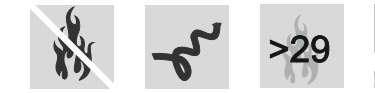
Fire behaviour is tested to DIN EN/IEC 60332-1-2, which evaluates the flame-retardant behaviour of a single insulated cable. The oxygen index exceeds 29, meaning the cable requires an atmosphere of more than 29 % oxygen to sustain combustion — significantly above the 21 % ambient oxygen level in normal air. This is an important safety metric in underground mining, where fire propagation in confined headings must be minimised.
Oil resistance is qualified to DIN EN/IEC 60811-404, ensuring the outer sheath does not degrade when exposed to hydraulic fluid, lubricating oils, or diesel — all routine contaminants in mining machinery environments.
The cable also carries RoHS 2015/863/EU compliance for hazardous substance restrictions and a CPR (Construction Products Regulation) 305/2011 declaration, supporting documentation requirements for projects that must demonstrate regulatory conformity under EU or GCC-aligned procurement frameworks.
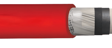
Cable Construction: Layer by Layer
Understanding the construction of the NTMCGCWOEU helps engineers make confident decisions about termination methods, accessories, and handling procedures on site.
Conductor. The heart of the cable is a finely stranded tinned copper conductor, Class 5 per IEC 60228. Tinning protects individual wires against corrosion from moisture and sulphur compounds — both present in underground mining atmospheres — and makes termination with compression lugs more consistent. The fine stranding is what delivers the flexibility that distinguishes this cable from solid or Class 2 conductors used in fixed-run cables.
Inner semi-conductive layer. Immediately over the conductor, an extruded semi-conductive stress control layer smooths the electric field distribution and eliminates air voids at the conductor-insulation interface. In medium voltage cables, these air voids would otherwise experience partial discharge — the primary long-term degradation mechanism in MV insulation — so this layer is critical for service life.
EPR insulation. The main insulation is an ethylene propylene rubber (EPR) compound formulated to DIN VDE 0207-20 with improved electrical and mechanical characteristics. EPR offers excellent tracking resistance, good performance at elevated temperatures, and inherently better flexibility at low temperatures compared with XLPE — a meaningful advantage in desert mining environments where cables may be coiled and stored outdoors during cold nights before installation.
Outer semi-conductive insulation shield layer. A second semi-conductive layer over the insulation forms the electrostatic screen interface. Together with the inner layer, it ensures a smooth, controlled field transition between the high-voltage insulation and the earthed metallic screen.
Protective conductor (screen). Tinned copper wires are spirally applied over the insulation shield to form both the capacitive screen (earthed at one or both ends depending on the system earthing arrangement) and the fault-current return path. The screen is designed in accordance with DIN VDE 0250-1.
Outer sheath. The outermost layer is a heavy-duty rubber compound, type 5GM5, complying with DIN VDE 0207-21. The sheath is coloured red — the standard identification colour for mining cables in many international markets — with inkjet marking for cable identification. It provides unrestricted service indoors and outdoors, with resistance to ozone, UV radiation, and moisture.
Key Technical Parameters
Thermal ratings define where and how the cable can be deployed. For fixed installation — where the cable is clamped or tied and not subjected to repeated movement — the ambient temperature range is -40 °C to +80 °C. For flexible operation — where the cable is repeatedly flexed, such as in a trailing or reeling application — the permissible range narrows to -25 °C to +80 °C, because rubber compounds become less pliable at very low temperatures and repeated flexing below -25 °C can cause micro-cracking in the insulation or sheath.
The maximum permissible conductor temperature in continuous normal operation is 90 °C, which drives the current-carrying capacity calculations. Under short-circuit conditions, the conductor may reach 200 °C for the brief duration of a fault before protective devices clear it — this is the parameter used to verify that the conductor cross-section can handle prospective fault currents without thermal damage.
De-rating factors for grouped installations, non-standard ambient temperatures, or buried routing are applied in accordance with DIN VDE 0298-4.
Mechanical parameters govern how the cable is handled on site. The maximum tensile load per conductor is 15 N/mm² — meaning for a 95 mm² conductor, the allowable pulling force is 95 × 15 = 1,425 N. This limit prevents conductor elongation, insulation separation, or screen damage during installation.
Minimum bending radius is 6 × outer diameter for fixed installation and 10 × outer diameter for free-moving or trailing applications. For a typical 1×95/16 mm² cable at 8.7/15 kV with an outer diameter of approximately 32–35 mm, this means a minimum bend radius of roughly 192–210 mm for fixed use and 320–350 mm for moving applications.
Electrical parameters cover the full rated voltage range. At 3.6/6 kV, the AC test voltage per DIN VDE 0250-813 is 11 kV, and the maximum permissible operating voltage is 4.2/7.2 kV in AC systems and 5.4/10.8 kV in DC systems. At the top of the range (18/30 kV), the AC test voltage rises to 43 kV and maximum operating voltages reach 20.8/36 kV (AC) and 27/54 kV (DC). These parameters confirm which system voltage levels the cable is approved for in the project's earthing and protection design.
Current-carrying capacity is tabulated per IEC 60364-5-52, with a reference ambient of 30 °C, conductor temperature of 90 °C, free in air, installation method F, three loaded conductors in trefoil. As a representative example, a 1×95/16 mm² cable at 8.7/15 kV carries approximately 1,830 A under these reference conditions, while a 1×240/25 mm² at the same voltage rating carries approximately 3,540 A. Engineers should apply de-rating factors from DIN VDE 0298-4 for site-specific conditions.

Middle East Mining Case Studies
Case Study 1 — Ma'aden Wa'ad Al-Shamal Phosphate Complex, Saudi Arabia
The Wa'ad Al-Shamal industrial city in the Northern Borders Region of Saudi Arabia is home to one of the world's largest integrated phosphate production complexes, operated by Ma'aden (Saudi Arabian Mining Company) in partnership with Mosaic and SABIC. The site includes open-pit phosphate mines, a beneficiation plant, a phosphoric acid plant, and a diammonium phosphate (DAP) fertiliser facility, all connected by an internal 115 kV and 33 kV power grid fed from dedicated substations.
Within the medium voltage distribution layer at 33 kV and 13.8 kV, flexible single-core screened cables in the NTMCGCWOEU configuration are specified for short-length connections between medium voltage switchgear cubicles and transformer bushings inside the main receiving substation buildings. The temperature range at this desert site — from -5 °C in winter to above 45 °C in summer — sits comfortably within the -40 °C to +80 °C fixed installation envelope of the cable. The red outer sheath is readily identifiable in the congested cable trays inside switchgear rooms, and the oil-resistant sheath performs reliably in areas where transformer insulating oil or hydraulic fluid from mobile maintenance equipment may be present.
The Class 5 conductor flexibility enables installers to route cables through tight bends inside the switchgear cubicles without exceeding the 6 × outer diameter bending limit, reducing installation time and avoiding the risk of insulation damage from forced bending that occurs when stiffer cable types are forced through compact cabinet layouts.
Case Study 2 — Muscat Mining Company, Rakah Copper Project, Oman
Oman's copper mining history dates back millennia, and the Rakah project operated by Muscat Mining Company (a subsidiary of Minerals Development Oman) represents modern open-pit copper mining in the Sultanate. The project uses mobile transformer substations — trailer-mounted 11 kV/690 V units — that are repositioned as the mine bench advances, requiring cable connections that can be disconnected, re-routed, and reconnected repeatedly.
At the 11 kV level (corresponding to the 6/10 kV voltage rating), flexible single-core screened cables in the NTMCGCWOEU format are used as the tails connecting the mobile substation's high-voltage terminals to the fixed overhead line drop-off structure. These tails are typically 5–15 metres long, but must be coiled and uncoiled during substation moves. The 10 × outer diameter minimum bending radius for free-moving use is the governing parameter here, and the EPR insulation's low-temperature flexibility ensures cables remain manageable during early-morning repositioning when ambient temperatures may be below 10 °C.
The UV resistance of the 5GM5 outer sheath is particularly relevant in Oman's high solar irradiance environment, where cables may be exposed on the surface for extended periods. Standard PVC-sheathed cables would chalk, crack, and harden under sustained UV exposure; the rubber sheath remains flexible and intact throughout the service life of the substation tail.
Case Study 3 — Emirates Steel, Abu Dhabi Industrial Infrastructure
While not a greenfield mine, Emirates Steel's integrated steelmaking complex in Mussafah, Abu Dhabi, operates extensive medium voltage infrastructure for its electric arc furnaces, rolling mills, and auxiliary equipment. The facility's 33 kV and 11 kV distribution system includes numerous short-length flexible connections between ring main units, transformer bushings, and power factor correction banks housed in adjacent switchgear rooms.
In the harsh industrial environment of Abu Dhabi — high humidity near the coast, elevated ambient temperatures, and diesel fume contamination in outdoor switchgear areas — the combination of oil-resistant sheathing (EN 60811-404) and ozone/UV resistance makes the NTMCGCWOEU construction the natural specification choice for internal flexible interconnects. The 24-month warranty and CPR compliance documentation also satisfy the contractor qualification and procurement documentation requirements typical of Abu Dhabi's infrastructure projects governed by ADNOC and Abu Dhabi Department of Energy procurement frameworks.
Operating Conditions and Installation Guidance
Fixed installation describes scenarios where the cable is installed once and not subsequently moved: internal wiring of switchgear cubicles, cross-bonding connections between cable screens, or permanent connections inside transformer houses. In these applications, the cable is clamped or supported at regular intervals, tensile loads are managed through cable glands and strain relief fittings, and the minimum bending radius of 6 × outer diameter applies.
Flexible operation describes applications where the cable is repeatedly flexed during service: mobile substation tails, reeling drum applications, or connections to traversing equipment. Here the 10 × outer diameter bending radius applies, and the lower ambient temperature limit of -25 °C must be respected during operation. Cables must not be flexed when they have been exposed to temperatures below -25 °C — they should be allowed to warm before movement.
Terminations and accessories for screened single-core medium voltage cables require stress control at the screen cut-back point. Cold-shrink or heat-shrink termination kits with integrated stress cones provide the required electric field management. Screen continuity and earthing must be maintained at termination points in accordance with the system earthing design and IEC 60287 screen bonding guidance.
Grouping and de-rating apply when multiple cables are installed together. Current-carrying capacity values from the datasheet assume single-circuit installation in free air at 30 °C ambient. For multi-circuit arrangements — common in switchgear rooms with multiple feeders leaving through the same cable entry — de-rating factors from DIN VDE 0298-4 must be applied to ensure conductors remain within the 90 °C thermal limit.
Selection and Specification Guide
Selecting the correct NTMCGCWOEU variant for a project follows a straightforward sequence.
First, establish the system rated voltage (U₀/U) and confirm the cable voltage rating covers it, with margin. For a 13.8 kV nominal system with solid earthing, the 8.7/15 kV rated cable is the correct choice. For a 20 kV isolated neutral (IT) system common in some European-influenced mining standards, the 12/20 kV rating applies.
Second, determine the maximum load current at the cable's installation location, apply the relevant de-rating factors, and select the conductor cross-section whose rated current exceeds the de-rated load. Verify that the conductor's short-circuit rating (using the 200 °C limiting temperature) also covers the prospective fault current and clearing time at the installation point.
Third, confirm the installation type — fixed or flexible — and check that the ambient temperature range, minimum bending radius, and tensile load limit are all respected in the specific installation geometry.
Fourth, specify the protective conductor cross-section (16, 25, or 35 mm² in standard configurations) to meet the fault loop impedance requirements of the system's earth fault protection relay settings.
Custom cross-sections and configurations can be produced on customer request, as noted in the manufacturer's datasheet.
Frequently Asked Questions (FAQ)
Q: What is the NTMCGCWOEU cable used for? The NTMCGCWOEU is a medium voltage screened single core flexible rubber cable used for short-length connections in switchgear rooms, transformer houses, and mobile mining substations where a small bending radius and high mechanical flexibility are required. It is rated from 3.6/6 kV to 18/30 kV per DIN VDE 0250-813.
Q: What standard does the NTMCGCWOEU comply with? The primary standard is DIN VDE 0250-813, covering medium voltage rubber cables for mining and heavy industrial use. Additional standards include DIN EN/IEC 60228 (conductor class), DIN VDE 0207-20 (EPR insulation), DIN VDE 0207-21 (rubber sheath type 5GM5), EN/IEC 60332-1-2 (fire behaviour), and EN/IEC 60811-404 (oil resistance).
Q: What is the minimum bending radius for NTMCGCWOEU? For fixed installation, the minimum bending radius is 6 times the cable's outer diameter. For free-moving or flexible applications — such as mobile substation tails — the minimum is 10 times the outer diameter. Exceeding these limits risks damage to the insulation screen layer and the EPR insulation.
Q: What temperature range can the NTMCGCWOEU operate in? For fixed installations, the ambient temperature range is -40 °C to +80 °C. For flexible operation (repeated bending during service), the range is -25 °C to +80 °C. The maximum conductor temperature in normal continuous operation is 90 °C, and the short-circuit limit is 200 °C at the conductor.
Q: What cross-sections are available for the NTMCGCWOEU? Standard cross-sections range from 16 mm² to 500 mm² for the main conductor, with protective conductor cross-sections of 16 mm², 25 mm², or 35 mm² depending on the main conductor size. Custom cross-sections can be produced on request.
Q: Is the NTMCGCWOEU suitable for outdoor use? Yes. The type 5GM5 rubber outer sheath provides unrestricted indoor and outdoor use, with resistance to ozone, UV radiation, and moisture. It is also oil-resistant per EN/IEC 60811-404, making it suitable for mining environments where exposure to hydraulic fluid, lubricating oil, or diesel fuel is possible.
Q: How is the NTMCGCWOEU different from a standard XLPE medium voltage cable? The NTMCGCWOEU uses EPR insulation and a rubber outer sheath rather than XLPE insulation and PVC or PE outer jacket. This gives significantly higher flexibility (Class 5 conductor vs Class 2 for most fixed-run MV cables), better low-temperature performance, superior UV and ozone resistance, and oil resistance — all characteristics required for short-length flexible connections in mining but not critical for long fixed distribution runs where standard XLPE cable excels.
Q: Can the NTMCGCWOEU be used in DC systems? Yes. The cable carries rated DC operating voltage specifications alongside its AC ratings. For example, at the 3.6/6 kV AC rating, the maximum permissible DC operating voltage is 5.4/10.8 kV. At the 18/30 kV AC rating, the DC limit is 27/54 kV. This covers medium voltage DC mining distribution systems and traction applications.
Q: What is the oxygen index of the NTMCGCWOEU outer sheath? The oxygen index exceeds 29, meaning the sheath material requires an atmosphere with more than 29 % oxygen to sustain combustion. Since normal air contains 21 % oxygen, this provides inherent flame resistance — an important safety characteristic for cables installed in underground mining headings where fire suppression and evacuation are critical concerns.
Q: How do I select the correct voltage rating for my mining system? Match the cable's U₀/U rating to the system's phase-to-earth voltage (U₀) and phase-to-phase voltage (U) as determined by the nominal voltage and the earthing arrangement. For a solidly earthed 11 kV system: U₀ = 6.35 kV, U = 11 kV — use the 6/10 kV or 8.7/15 kV cable depending on earthing category. For an isolated (IT) 11 kV system where full line voltage appears phase-to-earth under first-fault conditions, use the 8.7/15 kV or 12/20 kV rating. Consult IEC 60183 for formal voltage designation guidance.
Conclusion
The NTMCGCWOEU represents a well-engineered solution to a specific and demanding problem: connecting medium voltage equipment reliably in environments where standard fixed-run cables are too stiff, too brittle at low temperatures, and too vulnerable to UV, oil, and mechanical impact to survive operational service.
From the phosphate mines of Saudi Arabia's Northern Borders to the copper operations of Oman and the steelworks of Abu Dhabi, Middle Eastern industrial operations encounter the full range of conditions — extreme temperature swing, high UV intensity, hydrocarbon contamination, and the mechanical demands of mobile equipment — that the NTMCGCWOEU construction was designed to address.
For project engineers specifying medium voltage flexible interconnects in mining or heavy industrial projects across the GCC and broader Middle East region, the cable's DIN VDE 0250-813 compliance, broad voltage range, Class 5 conductor flexibility, and comprehensive chemical and fire resistance properties make it a specification-grade solution backed by a traceable international standards framework.
Technical data sourced from the NTMCGCWOEU product datasheet. Current-carrying capacity values apply per IEC 60364-5-52, conductor temperature 90 °C, reference ambient 30 °C, free in air, installation method F, three loaded conductors in trefoil. Consult manufacturer data and de-rating tables for site-specific installation conditions. BITNER reserves the right to modify specifications without prior notification.
Port crane cables | Mining cables | Reeling cables | Trailing cables | Festoon cables | Heavy-duty power cables | Medium voltage cables | Offshore crane cables | Underground mining cables | Dragline cables | Shearer cables | Container handling cables | STS crane cables | RTG cables | Mobile equipment cables | Armored cables | Flexible power cables | VFD cables | Submersible cables | Cold resistant cables | Abrasion resistant cables | Flame retardant cables | Marine environment cables | Opencast mining | Underground operations
© 2006 All rights reserved.
[INDUSTRIAL_CABLES]
INDUSTRIAL GRADE CABLE SYSTEMS | PORT & MINING SOLUTIONS
TEL: +86 153 7530 2641 |MAIL: hongjing.Wang@feichuncables.com