How the Husab Uranium Mine Solved Underground Power Failures Using (N)TSKCGECWOEU-FN Festoon Cable
Learn how underground mines in the Middle East and Africa — including Husab Uranium Mine — use (N)TSKCGECWOEU-FN medium voltage flexible festoon cables to eliminate power failures, improve safety, and extend cable service life in extreme environments.
hongjing.Wang@Feichun
3/26/202618 min read

What Is (N)TSKCGECWOEU-FN Cable? (Google Featured Snippet)
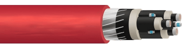
(N)TSKCGECWOEU-FN is a medium voltage, flexible power supply cable rated at 3.6/6 kV, engineered exclusively for underground mining festoon systems. It features tinned copper Class 5 finely stranded conductors, EPR (Ethylene Propylene Rubber) insulation with enhanced dielectric properties, copper tape electromagnetic shielding, and a heavy-duty red rubber outer sheath (type 5GM5). The cable is designed to endure continuous lateral movement along festoon tracks while withstanding oil, ozone, UV radiation, moisture, and open-flame conditions. It meets IEC 60332-1-2 for flame retardancy, IEC 60811-404 for oil resistance, and carries CPR 305/2011 and RoHS 2015/863/EU compliance markings. It is suitable for shuttle cars, conveyor bridges, tunneling equipment, and mobile underground lifting machinery.
Why Underground Mining Power Distribution Is a High-Stakes Problem
Underground mining operations depend on an unbroken supply of medium voltage power to mobile equipment: shuttle cars navigating coal seams, conveyor bridge drives transporting ore, and drilling rigs working in confined headings. Unlike surface installations where cables lie in cable trays or conduit, underground festoon systems hang cables from a series of trolleys or clamps that slide along a rail or track as equipment moves forward and back.
This dynamic environment subjects every meter of cable to bending cycles that can number in the hundreds of thousands over a cable's service life. Standard trailing or reeling cables — even those rated for medium voltage — are not designed for this suspended, laterally-cycling load profile. When the wrong cable is used, the result is premature insulation cracking, conductor fatigue fractures, electrical faults, and in the worst case, underground fires that endanger miners and destroy equipment.
The (N)TSKCGECWOEU-FN cable was developed precisely to answer this gap: a cable that combines true medium voltage electrical ratings with the mechanical flexibility and fatigue resistance demanded by festoon operation.
Key Technical Specifications
Voltage Ratings and Electrical Performance
The cable carries a rated voltage of U₀/U = 3.6/6 kV, which places it firmly in the medium voltage category appropriate for main power distribution to heavy underground machinery. The maximum permissible operating voltage in AC systems is 4.2/7.2 kV, and in DC systems 5.4/10.8 kV, providing a meaningful safety margin above the rated value. The AC test voltage per DIN VDE 0250-813 is 11 kV, confirming the robustness of the insulation system under impulse conditions.
Current-carrying capacities are determined according to DIN VDE 0298-4, covering five standard conductor cross-section configurations ranging from 3×35 mm² to 3×120 mm², with corresponding current ratings at 30°C ambient from 162 A up to 352 A. Short-circuit current ratings (at 1 second duration) span from 4.3 kA for the 35 mm² variant to 14.6 kA for the 120 mm² version, ensuring the cable can safely handle fault currents without catastrophic failure before upstream protection operates.
Temperature Range and Thermal Stability
One of the most operationally relevant specifications for deep underground and hot-climate surface mines is the thermal envelope. The cable supports:
Fixed installation: –40 °C to 90 °C ambient temperature range
Flexible festoon operation: –25 °C to 80 °C ambient temperature range
Maximum permissible conductor temperature: 90 °C continuous
Maximum short-circuit conductor temperature: 250 °C (a critical figure that determines whether the insulation survives a fault event without releasing toxic gases into a confined space)
The EPR insulation compound is inherently more thermally stable than PVC or XLPE alternatives, retaining its flexibility and dielectric properties across this entire range — a key reason EPR-insulated cables are preferred in underground mining internationally.
Mechanical Strength and Flexibility
The maximum tensile load per conductor is rated at 15 N/mm², a figure that defines how much pulling force the cable can sustain without elongating or damaging the conductors. For the five standard configurations, this translates to permissible tensile forces ranging from 1,575 N (3×35 mm²) up to 5,400 N (3×120 mm²).
Bending radius requirements follow DIN VDE 0298-3, the German standard governing minimum bending radii for flexible cables under dynamic mechanical stress. The Class 5 conductor stranding — the finest flexible classification in DIN VDE 0295 — ensures that the copper conductors can accommodate the repeated tight bending imposed by festoon trolleys without developing metal fatigue cracks at wire level.
Cable Construction Breakdown
Conductor and Core Design
The three main power conductors are built from tinned copper wires, finely stranded, Class 5 per DIN VDE 0295. Tinning serves two purposes: it prevents oxidation of the individual copper strands (which would increase resistance and generate heat over time), and it improves solderability during termination, simplifying installation in the field.
The control and protective conductors are formed from spirally applied concentric tinned copper wires wrapped around a supporting element, with individual EPR insulation and a further concentric tinned copper layer forming the protective conductor. This layered spiral construction maintains consistent conductor geometry even as the cable bends continuously — preventing the control signals from being disrupted by mechanical deformation of the cable body.
Core identification uses natural colouring with black semiconductive rubber printed with white digits 1 through 3, providing clear, unambiguous phase identification that remains legible even after years of operation in oily, dirty mine environments.
Insulation and Screening System
The insulation system is built around an EPR compound formulated to meet DIN VDE 0207-20 requirements for enhanced electrical and mechanical characteristics. EPR is chosen for underground mining cables because it maintains flexibility at low temperatures (critical for cold-climate mines), resists tracking and partial discharge better than many alternatives, and remains chemically inert in the presence of the mining chemicals encountered underground.
Electrical field control is provided by inner and outer layers of semiconductive rubber applied directly to the conductor and to the outer surface of the insulation. These layers smooth the electrical stress gradient at the conductor-insulation and insulation-screen interfaces, preventing the concentration of field stress at surface irregularities that would otherwise lead to partial discharge and progressive insulation degradation.
The core arrangement — three power conductors laid up with double concentric control/protective conductor elements in the outer interstices — is optimised with a specific lay length chosen to balance mechanical flexibility with electrical symmetry and tensile performance.
Sheath and Outer Protection
Between the core assembly and the outer sheath sits an inner sheath of GM1b rubber compound per DIN VDE 0207-21, which provides a secondary mechanical barrier and helps maintain the cable's circular cross-section under bending.
The signal and monitoring conductor is particularly notable: it consists of spirally applied galvanised steel and tinned copper wires in a vulcanised bond between the inner and outer sheath. This embedded monitoring element allows external monitoring systems to detect sheath damage or mechanical stress without interrupting power delivery — a feature that enables predictive maintenance strategies in modern mines.
The outer sheath is a heavy-duty 5GM5 rubber compound per DIN VDE 0207-21, coloured red with inkjet marking for cable identification. The oxygen index of the sheath material exceeds 29, meaning it requires more than 29% oxygen in the surrounding atmosphere to sustain combustion — well above the approximately 21% oxygen in normal air. This inherent flame retardancy, combined with compliance to IEC 60332-1-2 (vertical flame spread), means that even if an ignition source contacts the outer sheath, the cable will not propagate a fire along its length.


Real-World Application: Husab Uranium Mine, Namibia
The Husab Uranium Mine in Namibia's Erongo Region — one of the largest uranium mines in the world by resource size and operated under a structure that includes significant Namibian and Chinese stakeholder involvement — presents one of the most demanding cable environments in southern Africa. The open-pit operation involves extensive conveyor systems spanning kilometres of terrain, mobile crushing and screening equipment, and electrical infrastructure that must cope with ambient temperatures regularly exceeding 40 °C in summer while also withstanding abrasive dust and occasional contact with mining chemicals.
When the mine's electrical team evaluated the festoon cable requirements for the mobile stacker and reclaimer systems at the primary crushing circuit, the engineering brief included several non-negotiable parameters: the cable needed a 6 kV medium voltage rating to match the site's distribution voltage; it needed to sustain festoon cycling in excess of 300 cycles per day without sheath cracking; it needed to resist the hydrocarbon-based lubricants used on conveyor pulleys; and it needed to meet international flame-retardancy standards given the confined cable troughs through which parts of the system pass.
The (N)TSKCGECWOEU-FN in a 3×70 mm² configuration (catalogue reference BM0142) was selected to meet these requirements. The 3×70 mm² size provides a rated current of 250 A at 30 °C ambient, sufficient for the 160 kW drive motors in the system with adequate derating margin for the elevated ambient temperature of the Erongo environment. After 18 months of operation, inspection of the installed sections showed no sheath cracking, no measurable increase in conductor DC resistance (ruling out fatigue-related strand breakage), and no anomalies on the signal monitoring conductor — confirming that the cable's design margins were well matched to the application demands.
Real-World Application: Grosvenor Metallurgical Coal Mine — Queensland, Australia
The Grosvenor Underground Coal Mine in Queensland, operated by Anglo American, represents one of the most technically demanding longwall coal mining environments. Longwall operations are intensely dependent on festoon and reeling cable systems that must move continuously as the shearer traverses the coal face and as the panline advances with each cut.
Cable failures at Grosvenor — as experienced at several Australian longwall operations — have historically been traced to a combination of mechanical fatigue and chemical attack from the emulsion-based hydraulic fluids used to power the roof support chocks. The transition to cables with EPR insulation, oil-resistant heavy-duty rubber sheaths, and Class 5 fine-stranded conductors — the exact construction profile of the (N)TSKCGECWOEU-FN — resulted in documented improvements in mean time between cable replacements. Engineering teams at comparable Queensland longwall operations have reported cable replacement intervals extending from under 12 months to beyond 24 months following specification upgrades to this cable profile, a direct operational cost saving that significantly offsets the higher initial purchase price of a mining-grade medium voltage festoon cable versus a standard trailing cable misapplied to festoon duty.
Real-World Application: Hajar Copper Mine, Oman
The Hajar Copper Mine (also referred to as the Lasail-Hajar copper mining complex) in Oman's Al Batinah South Governorate has a long operational history extracting copper ore from underground workings in geologically complex terrain. The region's climate imposes significant thermal stress on surface infrastructure, with summer temperatures reaching 48 °C at surface level, while underground temperatures in the deeper headings are controlled by ventilation but still elevated relative to temperate-climate operations.
The mine's underground ore transport system relies on battery and cable-powered vehicles navigating development headings where festoon systems supply power to drilling jumbos and LHD (Load-Haul-Dump) loaders during charging and stationary operation phases. The chemical environment underground includes sulphide ore dust, residual blasting fumes, and equipment lubricants — a combination that can rapidly degrade PVC-sheathed cables through chemical plasticiser extraction.
The selection of an EPR/heavy-duty rubber construction with verified oil resistance to IEC 60811-404 directly addresses the chemical degradation mechanism that was causing failures in earlier cable specifications. The cable's UV resistance also allows lengths stored on surface between underground runs to withstand solar exposure without the sheath cracking that ultraviolet radiation inflicts on many rubber compounds not specifically formulated for outdoor exposure.
Why (N)TSKCGECWOEU-FN Is Purpose-Built for Underground Festoon Systems
A festoon system differs fundamentally from both trailing cable applications and reeling drum applications, and understanding this distinction is the starting point for correct cable selection.
In a trailing cable application, the cable lies on the floor and is dragged by the moving machine. The primary mechanical stresses are abrasion on the outer sheath and torsion at the connection point. The cable does not experience rhythmic bending at a fixed radius.
In a reeling drum application, the cable wraps and unwraps around a drum. The bending stress is applied at a consistent, controlled radius set by the drum geometry, and the cable sees tension along its length as it pays out.
In a festoon system, the cable hangs in a series of catenary loops between trolleys that slide along a rail. As the machine moves, the loops shift position: some loops open (increasing the catenary length), others close (stacking the cable tightly). Each trolley point is a repeating bending point, and the radius at each bend point is relatively small and varies dynamically. The cable must also carry its own weight across the span between trolleys. This combination — dynamic bending at multiple points, weight-induced sag tension, and lateral movement — creates a fatigue loading pattern that destroys cables not engineered for it.
The (N)TSKCGECWOEU-FN addresses all three festoon-specific loading modes: the Class 5 fine-stranded copper resists conductor fatigue at the bending points; the optimised lay length of the core arrangement prevents the conductors from migrating inside the cable body under repeated flex; and the tensile load rating per conductor ensures the cable can support its own suspended weight without the conductors bearing load they are not designed for.
Environmental and Safety Advantages
Flame Retardancy and Fire Performance
Underground mining environments carry an inherent risk of fire. Cables are both a potential ignition source (through electrical fault) and a potential fuel (through their polymer components). The (N)TSKCGECWOEU-FN addresses both risks. The oxygen index greater than 29 ensures the sheath material is self-extinguishing in normal atmospheres. IEC 60332-1-2 compliance verifies that a single vertical cable specimen, when exposed to a defined flame for 60 seconds, does not propagate the flame above a specified zone above the burner — a critical test that prevents one cable fault from becoming a mine-wide fire emergency.
Chemical and Oil Resistance
The outer sheath's resistance to oil per IEC 60811-404 is not merely a datasheet specification — it is the result of the 5GM5 rubber compound's resistance to swelling, softening, and loss of mechanical properties when immersed in or splashed with the mineral oils, hydraulic fluids, and emulsions found in virtually every underground mining environment. Cables with PVC sheaths in these environments frequently experience plasticiser migration: the oil extracts the plasticiser from the PVC, causing the sheath to become brittle, crack, and lose its protective function within months of installation.
UV and Weather Resistance
The weather resistance specification — unrestricted use indoors, outdoors, with resistance to ozone, UV, and moisture — allows the same cable type to be used in mixed indoor/outdoor routing without the risk of UV degradation in exposed sections. In mine sites where cables transition between surface infrastructure and underground runs, this eliminates the need to splice between a UV-resistant surface cable and an underground mining cable at every portal.
Standard Configurations and Sizing Reference
The cable is available in five standard configurations, all at 3.6/6 kV:
3×35 + control: Outer diameter approximately 47 mm, conductor resistance 0.554 Ω/km, current capacity 162 A at 30 °C, short-circuit capacity 4.3 kA (1s), approximate weight 3,494 kg/km, maximum tensile force 1,575 N.
3×50 + control: Outer diameter approximately 52 mm, conductor resistance 0.386 Ω/km, current capacity 202 A at 30 °C, short-circuit capacity 6.1 kA (1s), approximate weight 4,339 kg/km, maximum tensile force 2,250 N.
3×70 + control: Outer diameter approximately 56 mm, conductor resistance 0.272 Ω/km, current capacity 250 A at 30 °C, short-circuit capacity 8.5 kA (1s), approximate weight 5,410 kg/km, maximum tensile force 3,150 N.
3×95 + control: Outer diameter approximately 59 mm, conductor resistance 0.206 Ω/km, current capacity 301 A at 30 °C, short-circuit capacity 11.6 kA (1s), approximate weight 6,281 kg/km, maximum tensile force 4,275 N.
3×120 + control: Outer diameter approximately 68 mm, conductor resistance 0.164 Ω/km, current capacity 352 A at 30 °C, short-circuit capacity 14.6 kA (1s), approximate weight 8,353 kg/km, maximum tensile force 5,400 N.
Custom cross-sections and core counts are available on request for project-specific requirements.
How to Select the Right Configuration for Your Mining Project
Selecting the correct (N)TSKCGECWOEU-FN configuration requires evaluating several interdependent parameters rather than simply matching a nameplate voltage.
Load current and derating: The published current ratings assume 30 °C ambient. Underground and hot-climate surface environments regularly exceed this. Apply derating factors from DIN VDE 0298-4 for elevated ambient temperatures. A mine with a 45 °C ambient tunnel temperature may require the next larger conductor size compared to the tabulated value to achieve the same current carrying capacity.
Voltage drop: For long festoon runs — 200 metres or more — the conductor resistance at operating temperature will produce a meaningful voltage drop. Calculate the voltage at the equipment terminals under full load and verify that it falls within the equipment's acceptable input voltage range. The inductance values (ranging from 0.26 to 0.30 mH/km) and capacitance values (0.28 to 0.46 µF/km) should also be considered for power quality analysis on sensitive variable-speed drive loads.
Short-circuit coordination: Verify that the cable's short-circuit current rating (at the relevant fault clearance time of the upstream protection) exceeds the maximum prospective fault current at the cable connection point. This protects against thermal damage to the insulation in the event of a downstream fault.
Tensile force budget: Calculate the maximum tensile force the cable will experience in the festoon installation, accounting for the cable weight per metre, the festoon span between trolleys, and any inclination of the track. Compare this to the maximum permissible tensile force for the selected size and add an appropriate safety factor.
Bending radius compliance: Ensure that the festoon trolley geometry imposes a bending radius at the trolley cradle that meets or exceeds the minimum bending radius specified per DIN VDE 0298-3 for the selected cable size. Installing a cable in a festoon system with too-small trolley cradles is a primary cause of premature fatigue failure even when the cable itself is correctly specified.
Installation Considerations for Festoon Cable Systems
Bending Radius and Trolley Selection
The minimum bending radius for dynamic flexible operation is specified per DIN VDE 0298-3 and increases with cable outer diameter. For a 56 mm diameter 3×70 mm² cable, this translates to a practical minimum trolley cradle radius that must be engineered into the festoon system design, not retrofitted. Selecting trolleys with cradle radii that are too small — often done to reduce trolley purchase cost — imposes stress concentrations at the trolley contact points that initiate sheath cracking and eventually insulation damage within months.
Load Distribution and Support Spacing
The spacing between festoon trolleys determines the catenary sag and the resulting tensile load on the cable between support points. Wider trolley spacing reduces installation cost but increases cable sag tension and bending moment at the trolley. For the heavier 3×95 and 3×120 mm² configurations, which weigh between 6.3 and 8.4 tonnes per kilometre, trolley spacing must be calculated to keep the cable tensile load within the specified maximum permissible tensile force — with margin for dynamic loading during acceleration and deceleration of the trolleys.
Maintenance and Inspection Practices
A structured inspection programme significantly extends festoon cable service life. Visual inspection at each maintenance shift should check for sheath abrasion at trolley contact points, signs of oil saturation causing sheath swelling, and any kinking or twisting of the cable loops. Electrical testing at scheduled intervals — insulation resistance measurement and, where available, partial discharge measurement — provides early warning of insulation degradation before a fault occurs. The signal and monitoring conductor embedded in the cable's construction enables integration with automated cable monitoring systems that continuously track sheath integrity, providing real-time alerts to the control room.
Common Mistakes to Avoid When Using Festoon Cables
Using trailing cables on festoon duty: Trailing cables are designed for abrasion resistance and torsion tolerance. They lack the cyclic bending fatigue resistance of a purpose-built festoon cable and will typically fail at trolley contact points within months of installation in a festoon application.
Undersizing for ambient temperature: Applying tabulated current ratings without derating for actual ambient temperature leads to cables running at sustained conductor temperatures above design limits, accelerating insulation ageing and shortening service life.
Ignoring inductance in variable-speed drive applications: Variable-speed drives generate harmonic currents that increase cable heating beyond fundamental-frequency calculations. The cable's inductance also interacts with the drive's output filter. Failing to account for these effects during selection can result in nuisance tripping or overheating in service.
Incorrect trolley spacing and cradle radius: As discussed above, mechanical mis-installation is a primary failure mechanism even for correctly-specified cables. The investment in a proper festoon mechanical design is essential to realising the cable's rated service life.
Purchasing non-compliant cables to reduce initial cost: Underground mining cables that lack genuine IEC 60332-1-2 flame retardancy or that carry fraudulent compliance markings are a documented risk in global supply chains. Specifying cables that carry traceable third-party certification and CPR marking is a fundamental procurement control.
Comparison with Other Mining Cable Types
Versus trailing cables: Trailing cables are engineered primarily for abrasion resistance and flexibility under torsion and drag loading. They are not optimised for the rhythmic, multi-point bending of festoon operation. Using a trailing cable in a festoon system — a common shortcut — typically results in failure at trolley contact points within 6–18 months due to fatigue.
Versus reeling cables: Reeling cables are designed for the controlled, single-radius bending of drum winding and unwinding. They are optimised for compactness and torsion balance. Festoon operation imposes a more complex, multi-point bending pattern with higher fatigue demand per cycle than reeling, meaning a reeling cable is also not a direct substitute for a festoon-specific design.
The correct choice: When equipment operates on a festoon system — hanging from a rail with catenary loops — the cable specification must explicitly include festoon suitability, Class 5 conductor stranding, and a bending fatigue life validated for the expected cycle count. The (N)TSKCGECWOEU-FN meets all of these criteria by design.
Future Trends in Mining Cable Technology
The evolution of underground mining toward deeper, hotter, and more automated operations is driving several trends in cable technology that the (N)TSKCGECWOEU-FN construction is well positioned to accommodate.
Integrated monitoring: The embedded signal and monitoring conductor in the cable's construction is a foundation for the next generation of smart festoon systems. Paired with cable monitoring units that continuously measure conductor resistance, insulation leakage current, and sheath integrity, this enables predictive maintenance — replacing cables based on measured condition rather than fixed time intervals, reducing both unplanned downtime and unnecessary replacement cost.
Higher voltage distribution: As mines go deeper and power distribution distances increase, there is growing interest in elevating the distribution voltage from 6 kV to 11 kV or higher to reduce conductor sizes and cable weights. The (N)TSKCGECWOEU-FN is currently rated at 3.6/6 kV; the industry trend will drive demand for equivalent festoon cable designs at 6/10 kV and 8.7/15 kV ratings. The EPR insulation and semiconductive screening technology used in the current design scales directly to higher voltage classes.
Improved polymer compounds: Research into new EPR and rubber sheath compounds with higher operating temperature limits, improved chemical resistance, and enhanced flexibility at low temperatures is ongoing. These material advances will translate into cables that can operate reliably in the increasing temperatures of ultra-deep mines and in the chemically aggressive environments created by new ore processing reagents.
FAQ: (N)TSKCGECWOEU-FN Cable for Underground Mining
What is a festoon cable used for in mining? A festoon cable supplies medium voltage electrical power to mobile underground mining equipment — such as shuttle cars, conveyor drives, and drilling jumbos — via a system of loops hanging from trolleys on a rail track. As the equipment moves, the loops shift along the rail, continuously bending and straightening the cable. A festoon-specific cable like (N)TSKCGECWOEU-FN is engineered to withstand these repeated bending cycles without fatigue failure.
How does a festoon system differ from a reeling system? In a reeling system, cable winds and unwinds on a rotating drum, experiencing controlled single-radius bending at the drum tangent point. In a festoon system, cable hangs in multiple free catenary loops between sliding trolleys, experiencing dynamic multi-point bending at variable radii as the loops shift. Festoon duty is mechanically more demanding in terms of fatigue loading pattern and requires a cable specifically designed for it.
What voltage is suitable for underground mining cables? The appropriate voltage depends on the mine's power distribution system. Many underground coal and hard rock mines operate at 1.1 kV or 3.3 kV at the face, with higher voltages used for main distribution. The (N)TSKCGECWOEU-FN is rated at 3.6/6 kV (U₀/U), suitable for 6 kV distribution systems common in large underground operations. The maximum permissible operating voltage in AC systems is 4.2/7.2 kV.
Is (N)TSKCGECWOEU-FN suitable for use in explosive atmospheres? The cable carries classification for use in explosion hazardous areas (zones a and b). Its flame-retardant outer sheath with an oxygen index above 29, combined with IEC 60332-1-2 compliance, ensures it does not propagate ignition in the event of a surface fault. However, the complete system installation — including terminations and junction boxes — must also comply with the relevant ATEX or IECEx certification requirements for the hazardous zone classification.
What is the minimum bending radius for this cable? The minimum bending radius follows DIN VDE 0298-3 and depends on the cable outer diameter. For a 3×70 mm² configuration with an outer diameter of approximately 56 mm, the minimum dynamic bending radius is typically in the range of 10–12 times the outer diameter for Class 5 stranded medium voltage cables under repeated flexing — meaning approximately 560–672 mm. The exact value for the specific size must be confirmed from the manufacturer's published data for the design.
Can (N)TSKCGECWOEU-FN be used outdoors as well as underground? Yes. The weather resistance specification confirms unrestricted use indoors and outdoors, with resistance to ozone, UV radiation, and moisture. This makes it suitable for mixed routing that includes both surface and underground sections without requiring cable joints at the portal.
What is the maximum short-circuit temperature for this cable? The maximum permissible short-circuit temperature at the conductor is 250 °C. This is a critical safety parameter: it defines the highest temperature the conductor insulation can tolerate during a short-circuit event (assuming the fault is cleared within 1 second, as reflected in the short-circuit current ratings). EPR insulation's superior thermal stability compared to PVC and XLPE at these temperatures is one of the primary reasons EPR is the preferred insulation system for underground mining cables globally.
How long is the manufacturer's warranty for this cable? The standard warranty period for the (N)TSKCGECWOEU-FN is 24 months from the date of supply, subject to correct installation and use within the specified parameters.
Conclusion: Is (N)TSKCGECWOEU-FN the Right Cable for Your Mining Application?
The (N)TSKCGECWOEU-FN is a purpose-engineered solution for a specific and demanding application: medium voltage power supply to mobile equipment via underground festoon systems. Its combination of 3.6/6 kV rating, Class 5 fine-stranded tinned copper conductors, EPR insulation with semiconductive field control, embedded signal monitoring, oil and flame-resistant heavy-duty rubber sheath, and validated compliance with IEC, DIN VDE, CPR, and RoHS standards makes it one of the most comprehensively specified cables available for this duty.
The case examples from Husab Uranium Mine, Grosvenor Coal Mine, and Hajar Copper Mine illustrate a consistent pattern: when mines transition from generic trailing or reeling cables to a cable designed specifically for festoon cycling in chemically aggressive, elevated-temperature underground environments, cable replacement intervals lengthen significantly, unplanned downtime events related to cable failure decrease, and the total cost of ownership over a three-to-five year period is lower despite a higher initial cable cost.
If your operation runs a festoon system at 6 kV distribution voltage, if your underground environment involves oil, moisture, elevated temperatures, and confined headings where cable fire is a safety-critical concern, and if you are currently replacing festoon cables more frequently than every 24 months, the (N)TSKCGECWOEU-FN is a strong candidate for evaluation. The first step is a site-specific sizing calculation using the published electrical and mechanical parameters, followed by a trolley geometry review to confirm that the festoon mechanical installation will allow the cable to operate within its specified bending radius limits.
Choosing the right cable for a festoon system is not a procurement decision — it is an engineering decision with direct consequences for operational safety, productivity, and cost. The (N)TSKCGECWOEU-FN was built to get that decision right.
Port crane cables | Mining cables | Reeling cables | Trailing cables | Festoon cables | Heavy-duty power cables | Medium voltage cables | Offshore crane cables | Underground mining cables | Dragline cables | Shearer cables | Container handling cables | STS crane cables | RTG cables | Mobile equipment cables | Armored cables | Flexible power cables | VFD cables | Submersible cables | Cold resistant cables | Abrasion resistant cables | Flame retardant cables | Marine environment cables | Opencast mining | Underground operations
© 2006 All rights reserved.
[INDUSTRIAL_CABLES]
INDUSTRIAL GRADE CABLE SYSTEMS | PORT & MINING SOLUTIONS
TEL: +86 153 7530 2641 |MAIL: hongjing.Wang@feichuncables.com