How to Extend the Service Life of Trailing Cables on Heavy-Duty Excavators
Discover the main causes of trailing cable failure on heavy-duty excavators and how proper installation, bending control, and maintenance can extend cable service life.
hongjing.Wang@Feichun
7/15/202614 min read
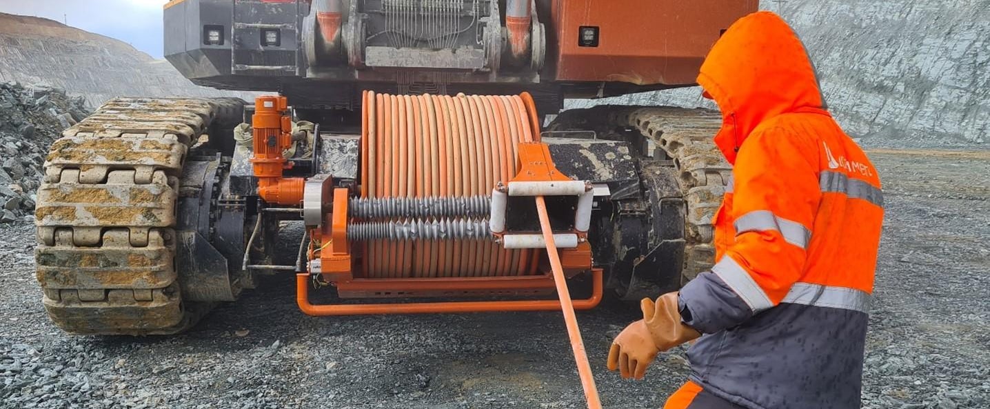
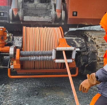
Heavy-duty mobile excavators, draglines, electric shovels, and bucket wheel excavators represent the financial engine of modern mining and quarrying operations. These massive machines require immense, uninterrupted electrical power to bite through solid rock, move hundreds of tons of earth per cycle, and maintain the aggressive production schedules demanded by modern infrastructure projects. Because these systems are constantly moving across vast working areas, they cannot be wired into permanent electrical grids. Instead, they rely entirely on heavy-duty trailing cables to deliver high-voltage power while adapting to the machine's dynamic movement pattern and rough ground conditions.
For project directors, maintenance managers, and procurement teams, these trailing cables are a frequent source of technical frustration. A common question heard across maintenance yards is: "Why does my cable break every six months?" In many demanding environments, trailing cables fail well before their designed operating lifetime, causing expensive unscheduled downtime, disrupting transport operations, and creating severe electrical safety hazards for nearby ground crews.
When an expensive high-voltage cable fails after only a few months of service, it is easy to blame bad luck, harsh ground conditions, or manufacturing defects. However, a detailed engineering analysis reveals a different reality. Early cable failure is rarely the result of bad luck. It is almost always driven by a predictable combination of excessive bending stress, crushing forces, continuous twisting, and severe outer jacket damage.
Understanding that cable degradation is a progressive process allows operators to change how they manage these critical assets. Extending trailing cable service life requires moving away from reactive replacement and adopting a comprehensive approach that combines correct cable selection, precise routing control, and disciplined field maintenance.
Why Trailing Cables Fail Too Early
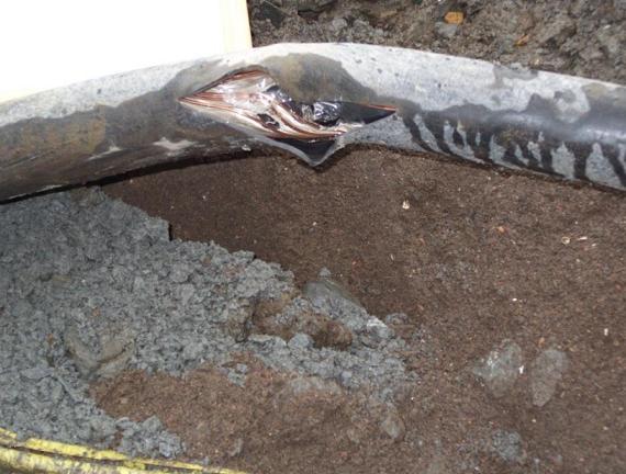
The premature breakdown of an excavator trailing cable is rarely an instantaneous event. Instead, it is the final step in a progressive chain of mechanical and electrical degradation. The process usually begins with a minor, unnoticed defect on the outer surface of the cable. A small scrape from a jagged piece of limestone, a slight pinch from a support vehicle, or a tight turn that exceeds the cable’s design limits will weaken the outer layer.
Once the outer jacket is compromised, the protective seal is broken. As the excavator continues its daily duty cycle, moving back and forth across the pit floor, the internal layers are exposed to intense physical forces. The initial jacket defect allows moisture, fine dust particles, and acidic mine water to seep inside the cable core.
Inside the cable, this moisture mixes with the dust to create an abrasive paste that grinds against the insulation layers as the cable flexes. Over weeks of continuous operation, this internal abrasion wears away the Ethylene Propylene Rubber (EPR) insulation surrounding the live phase conductors.
As the insulation grows thinner, the electrical field within the cable becomes unstable, leading to localized tracking and micro-arcing. Eventually, the insulation fails completely, allowing a live conductor to touch the earth screen or another phase core, resulting in a catastrophic phase-to-earth fault that trips the main circuit breaker and shuts down the entire machine.
This progressive failure model highlights an important operational reality: the ultimate service life of a trailing cable is primarily determined by installation quality and operating discipline, not just the initial purchase price. Buying the most expensive premium cable available will not prevent early failure if the cable is dragged over sharp rocks, run over by service trucks, or twisted continuously by poorly trained operators.
True operational cost efficiency is achieved when procurement and maintenance teams treat the cable as an engineered mechanical system that must be actively protected, monitored, and maintained throughout its working life.
Excessive Bending Stress
Every flexible trailing cable is engineered with specific mechanical boundaries, and one of the most critical limits is the minimum bending radius. The minimum bending radius represents the tightest arc a cable can safely form without causing internal structural damage. In the heavy industrial sector, this value is never left to guesswork; it is calculated using a standard multiplier formula:
Minimum Bending Radius = Cable Outer Diameter × Multiplier
This multiplier factor changes based on the construction of the cable, its voltage rating, and whether the cable is intended for stationary installation or continuous dynamic movement. For high-voltage mining trailing cables subjected to regular flexing, industry standards typically specify a multiplier factor of 6D, 8D, 10D, 12D, or even higher, depending on the exact service conditions.
If a cable has an outer diameter of 50 mm and is operating under a strict 12D bending rule, the minimum radius of any curve it forms must never drop below 600 mm, meaning the total diameter of the loop must be at least 1200 mm.
Incorrect Tight Bend (Under Multiplier Limit): ──────┐ │ <-- Intense localized compressive and tensile stress ──────┘ Correct Wide Bend (Compliant with 12D/15D Limit): ─────────╮ │ │ <-- Evenly distributed mechanical forces ─────────╯
When a cable is bent past this calculated limit, the physical forces inside the structure change dramatically. The materials on the outside curve of the bend are subjected to intense tensile stress, stretching the outer jacket and earth screens to their physical limits. At the same time, the materials on the inside curve suffer severe compressive stress, causing the internal insulation layers to bunch up and deform.
Repeatedly forcing a cable into tight bends causes rapid conductor fatigue. The individual fine copper strands within the phase cores begin to develop microscopic stress fractures. Over time, these fractured strands snap under mechanical tension, reducing the total cross-sectional area of the copper conductor.
As the cross-sectional area shrinks, the electrical resistance of the remaining intact strands increases, creating localized thermal hot spots. These hot spots bake the surrounding rubber insulation from the inside out, making it brittle and prone to electrical breakdown.
For excavator operators and ground crews, this damage is driven by common field behaviors. Forcing an excavator to make tight turns while dragging its power cable, allowing the cable to wrap tightly around structural components of the machine's undercarriage, or pulling the cable around sharp rock corners are all behaviors that shorten its operational life.
Every instance of over-bending permanently degrades the internal components of the cable, even if the outer jacket appears undamaged.
Cable Crushing Damage
In the busy environment of an open-pit mine or a large quarry, heavy mobile equipment is constantly moving. Beside the main excavator, the working area is shared by heavy haul trucks, track-mounted dozers, service vehicles, and light utility trucks. This constant flow of heavy equipment creates a continuous risk of cable crushing damage.
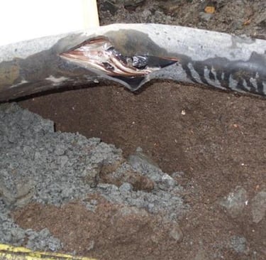
Crushing damage typically occurs when a trailing cable is run over by support vehicles, trapped under the massive weight of the excavator’s own crawler tracks, or pinched against hard rock faces due to poor routing choices. When a support vehicle or a multi-ton excavator track rolls over a cable lying on a hard pit floor, the cable is subjected to extreme compressive pressure.
A serious challenge with crushing damage is that modern heavy-duty elastomeric jackets are highly resilient. They can deform under massive weight and quickly snap back into a normal circular shape once the vehicle passes. This deceptive external appearance often leads ground crews to assume the cable is completely fine.
Inside the cable, the reality is very different. While the outer rubber jacket springs back into place, the intense pressure often causes the internal components to shift permanently. The soft EPR insulation surrounding the copper conductors can be flattened or pushed to one side, destroying the precise concentric geometry of the cable core.
This asymmetry creates thin spots in the insulation where the live copper conductor is positioned too close to the woven earth screen. Additionally, the crushing force can flatten the individual copper strands, causing them to lock together and losing the flexibility required for regular operation.
Intact Cable Geometry: Crushed / Asymmetric Core: _______ _______ / O \ / O \ | O . O | | O . O | <-- Thin insulation zone \___O___/ \___O___/
Once the internal insulation geometry is distorted, the cable becomes highly vulnerable to partial discharge. Over time, the high-voltage electrical field breaks down the weakened insulation layer at the pinch point, leading to an unexpected internal short circuit.
To prevent this type of failure, mine operators must move away from a reactive strategy that replaces cables only after they fail. The operational focus must shift to proactive protection, including clear cable routing paths, heavy-duty physical barriers, and elevated cable support systems that isolate the cable from all vehicle traffic.
Twisting and Torsion
Twisting and torsional stress represent major, yet frequently overlooked, causes of premature failure in mobile mining cables. Unlike a standard industrial power cable that remains static inside a protective conduit, an excavator trailing cable is exposed to constant directional changes as the machine swings its upper carriage, moves along the face, and repositions its boom.
Cable torsion failure occurs when a cable is twisted along its longitudinal axis, forcing the internal components to rotate against their original manufacturing orientation. High-voltage trailing cables are built using a specific planetary configuration, where the insulated phase conductors and ground wires are wound together in a precise helical pattern. This helical winding is designed to distribute mechanical loads evenly across the cable structure when it bends smoothly along a straight path.
When the cable is subjected to severe twisting forces—usually because it is unwound incorrectly from a storage reel or dragged in a looping pattern that prevents it from rotating naturally—this balanced helical geometry is destroyed. The twisting force tightens the helix in one direction while loosening it in the other, causing the internal layers to fight against each other.
Normal Helical Layup: Torsional Distress (Bird Caging): ============ ====// \\==== ============ ====\\ //==== └── Conductor strands ballooning outward
A common visible sign of severe torsional distress is a condition known as bird caging. When a cable is twisted against its lay direction, the individual copper strands within the conductors are forced to uncoil and balloon outward, pushing hard against the surrounding insulation layer. This structural deformation ruptures the internal tapes and tears the EPR insulation, destroying the cable's mechanical balance.
Once bird caging occurs, the cable loses its ability to bend safely, and the distorted copper strands can easily puncture the outer jacket from the inside out, causing an immediate electrical failure.
Jacket and Sheath Damage
The outermost layer of a trailing cable is its first line of physical defense against the punishing conditions of the mining environment. This heavy-duty elastomeric jacket is engineered to protect the delicate internal insulation layers and copper conductors from four primary environmental threats: physical abrasion, intense UV exposure, oil contamination, and chemical attacks.
Physical Abrasion
In most quarrying and extraction operations, the ground is covered in blasted rock fragments, sharp flint, and highly abrasive quartz dust. As the heavy excavator moves, the trailing cable is dragged across this rough surface under significant tension.
This continuous scraping action behaves like a heavy industrial grinding wheel, slowly wearing away the thickness of the outer rubber jacket. The wear is most intense at contact points near the machine’s mounting brackets and along the natural bend zones where the cable rubs against the ground.
Solar Radiation and Temperature Extremes
In many key mining regions, such as the Middle East and North Africa, trailing cables are exposed to intense solar radiation and high ambient temperatures. The combination of direct sunlight and ambient temperatures climbing past 40°C can accelerate the aging process of standard rubber compounds.
The ultraviolet (UV) rays break down the polymer chains within the outer sheath, causing the rubber to lose its elasticity. Over time, the jacket develops fine surface cracks, a process known as photo-oxidation. These cracks gradually deepen with every bend cycle, eventually opening up paths for water and dust to penetrate the cable core.
Chemical and Oil Contamination
Excavators and heavy mining machinery operate using massive volumes of pressurized hydraulic fluid, gear lubricants, and diesel fuel. Leaks, ruptured hoses, and careless maintenance practices can easily coat the trailing cable in these petroleum-based chemicals.
If the outer jacket is not formulated from highly specialized, oil-resistant polymers, contact with these oils will cause the rubber to swell, soften, and lose its mechanical strength. Once softened by oil contamination, the jacket can be easily torn open by ordinary rock contact.
Because the outer jacket serves as the vital primary barrier for the entire electrical asset, any deep cut, tear, or worn zone represents a critical vulnerability. Once the jacket is breached, the internal components degrade rapidly, making regular surface inspections a vital part of effective maintenance management.
How to Handle Cables Correctly
Preventing premature trailing cable failure requires training field crews and equipment operators in correct cable handling procedures. The most important rule for managing any moving trailing cable is simple: always maintain sufficient slack so the cable can move naturally without being stretched or pulled taut.
A cable that is pulled taut under tension behaves like a mechanical guitar string, absorbing all the shock loads and vibrations generated by the moving excavator. This intense tension stretches the internal copper conductors, leading to rapid material fatigue and structural failure. By ensuring the cable retains a relaxed, loose S-curve profile along the ground, the machine can move freely without subjecting the internal layers to damaging tension.
Dangerous Taut Setup: [Excavator] ────────────────────────────────────────── [Substation] (High tension, high risk of internal snapping) Safe Slack Setup: [Excavator] ───╮ ╭───╮ ╭───╮ ╭───────── [Substation] ╰──────┘ ╰──────┘ ╰──────┘ (Relaxed S-curves absorb movement safely)
Implementing Proper Cable Guides and Protective Routing
To reduce physical wear on the pit floor, operations should install high-quality cable guides, polyurethane rollers, and dedicated routing paths. Rather than allowing a cable to drag directly over sharp rocks, it should be supported by modular, high-visibility cable rollers that allow it to roll smoothly as the machine positions itself.
When a cable must cross a primary haul road used by heavy trucks, it must never be left exposed on the ground. Instead, operators should use heavy-duty rubber cable bridges or cut a dedicated trench filled with protective bedding sand to completely isolate the cable from vehicle weight.
Field Dos and Don'ts for Operating Crews
DO check the minimum bending radius before moving the cable, ensuring every loop remains wide, smooth, and within design limits.
DO use high-visibility polyurethane cable arches to lift the cable safely over minor walkways and secondary service tracks.
DO use clean, non-binding textile slings when lifting or repositioning a cable with support equipment, rather than using metal chains or excavator buckets that can pinch the jacket.
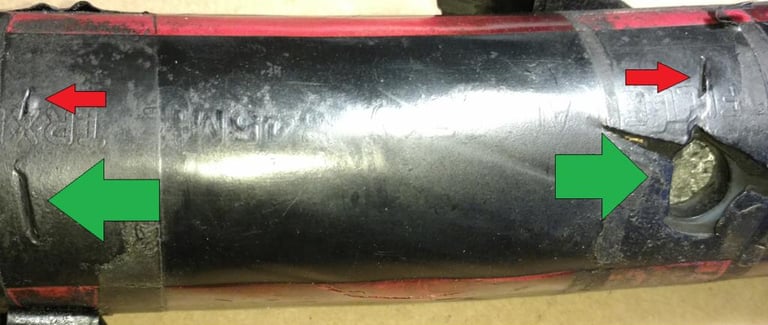
DON'T drag a trailing cable sideways across sharp, blasted rock faces or jagged steel structures.
DON'T allow a cable to form tight, twisted loops or kinks while it is being unwound from a storage reel.
DON'T clear rocks or clean the pit floor by driving a tracked dozer directly over an active, energized power cable.
Inspection and Maintenance Routine
Maintaining a long, reliable service life for trailing cables requires a disciplined inspection and testing schedule. Hidden mechanical and electrical defects often develop long before a total system short circuit occurs.
Establishing a regular maintenance rhythm allows technical teams to identify and repair minor issues early, preventing expensive unplanned downtime.
Daily Field Checks
At the start of every shift, the ground crew or designated maintenance technician should complete a brief visual inspection of the active cable line. This check focuses on identifying immediate physical threats and obvious structural defects:
Inspect the cable jacket for deep cuts, tears, or exposed copper strands.
Look for signs of flattening, twisting, or bird caging along the length of the cable.
Verify that the cable maintains proper slack and has not been pulled taut by recent machine movements.
Ensure all cable rollers turn freely and are clear of muddy buildup or rock blockages.
Check the entry points at the excavator's terminal box and the substation enclosure to ensure all strain-relief clamps are secure.
Weekly Technical Reviews
Once a week, a qualified electrician should perform a closer inspection along the entire length of the cable, focusing on high-wear zones and dynamic bending areas:
Clean accumulated grease, oil, and thick mud from the cable surface to inspect the condition of the underlying rubber jacket.
Measure the outer diameter of the cable at known wear points to check for severe jacket thinning caused by ground friction.
Inspect the condition of all temporary vulcanized patches or cold-shrink repair sleeves to ensure they remain watertight.
Examine the routing path to ensure the cable is clear of any recent rockfalls or standing water pools.
Monthly Electrical Diagnostic Testing
Once a month, the cable should be safely de-energized, isolated, and subjected to a comprehensive series of electrical diagnostic tests using specialized test equipment:
Insulation Resistance Testing: Use a high-voltage Megohmmeter (typically applying 1000V or 5000V DC based on the cable's voltage rating) to measure the resistance between individual phase conductors, and between each phase and the earth screen. These values should be recorded over time to track long-term insulation trends.
Continuity and Ground Loop Testing: Measure the resistance of the earth conductors and the low-voltage pilot wire loop to ensure all ground connections are intact and free of hidden breaks.
Jacket Integrity Inspection: Conduct a close physical check of the outer jacket to ensure no deep surface cracks have developed that could allow moisture to penetrate the core during the next operating cycle.
Excavator Cable Systems in Practice
The management principles outlined in this guide apply directly across a wide variety of large-scale mobile mining machines, including electric shovels, draglines, stackers, reclaimers, and massive bucket wheel excavators. While these machines vary in size and production purpose, they all share a common operational requirement: they need continuous high-voltage power while moving across large working areas.
The Machine-Cable System: ┌────────────────────────────────────────────────────────┐ │ OPERATING ENVIRONMENT │ │ (Ground Hardness, Abrasive Dust, Moisture, Chemistry) │ └───────────────────────────┬────────────────────────────┘ ▼ ┌───────────────────────────┴────────────────────────────┐ │ TRAILING CABLE LIFE │ │ (Determined by Path Routing and Handling Habits) │ └───────────────────────────┬────────────────────────────┘ ▼ ┌───────────────────────────┴────────────────────────────┐ │ MACHINE PRODUCTIVITY │ │ (Directly protected against unexpected outages) │ └────────────────────────────────────────────────────────┘
The interaction between a machine’s movement pattern and the surrounding ground conditions creates a unique stress profile for its trailing cable. For instance, a giant dragline tends to move slowly along a predictable, linear path, but its massive power requirement demands a thick, heavy cable that experiences intense tensile loads when pulled over long distances.
An electric shovel operates with a much faster duty cycle, turning and repositioning frequently within the pit. This rapid movement exposes its trailing cable to frequent directional shifts, making it vulnerable to twisting, kinking, and accidental tracking damage.
Ultimately, an industrial trailing cable should not be viewed as an isolated accessory. It is a vital component of the machine's primary operating system. When a cable fails, the entire excavator shuts down, halting production across the pit, leaving haul trucks idle, and disrupting downstream crushing and processing plants.
Connecting cable durability directly with overall machine productivity highlights the value of investing in high-quality management practices. Protecting the cable keeps the primary production asset running smoothly.
Why Some Cables Still Fail Despite Maintenance
On some sites, maintenance teams follow inspection checklists perfectly, yet their trailing cables continue to fail prematurely. This frustrating situation usually indicates that the cable failure is a symptom of a larger systemic problem rather than a simple maintenance oversight.
Even a premium cable will fail early if it is repeatedly exposed to conditions it was never designed to handle. Systemic failures generally stem from five common root causes:
Mismatched Technical Specifications
The selected cable construction may not match the actual physical reality of the application. For instance, if a mine procurement team orders a standard industrial cable with a thin, rigid PVC jacket to save on initial costs, that cable will quickly crack and fail when deployed on a high-flexibility excavator application that requires a heavy-duty, vulcanized elastomer sheath.
Severe Path Layout Errors
The layout of the pit floor may force the cable through impossible angles. If the structural layout of the transfer point or the position of the static substation forces the cable to bend below its minimum radius every time the excavator swings, no amount of daily inspection will prevent the internal copper strands from snapping.
Uncalibrated Slip Rings and Reels
Many large excavators use automated cable reeling systems to manage the cable as the machine moves. If the mechanical tension on these reels is set too high, the cable is subjected to a continuous pulling force that stretches the core. If the internal slip rings are poorly maintained, they can generate intense frictional heat that bakes the cable terminations from the inside out.
Weak Operational Discipline
A division between the electrical maintenance team and the heavy equipment operators can lead to premature failures. If operators are focused entirely on production targets and ignore proper cable positioning, they will continue to drag cables over sharp rock edges and run over them with support vehicles, undoing the work of the maintenance team.
Environmental Incompatibility
Deploying a cable designed for moderate climates into extreme environments—such as the intense heat and UV exposure of the Middle East, or the sub-zero temperatures of northern regions—without modifying the polymer formulation will lead to rapid jacket failure. Standard rubber sheaths quickly become brittle and crack under extreme conditions, allowing moisture to ruin the internal insulation.
Feichun Heavy-Duty Solutions
Addressing these complex challenges requires partnering with a dedicated cable manufacturer who understands the realities of modern mining and quarrying operations. Feichun has established a strong reputation by engineering high-performance trailing cables specifically designed to survive the harshest mechanical and environmental conditions.
The Feichun manufacturing philosophy rejects generic, multi-purpose industrial cable designs. Instead, Feichun focuses on manufacturing heavy-duty trailing cables using advanced vulcanized elastomer compounds that deliver excellent bend control, high abrasion resistance, and long-term electrical stability.
By utilizing thick, robust formulations for their outer sheaths, Feichun cables provide durable protection against physical impacts, surface scrapes, oil contamination, and intense UV exposure, making them well-suited for demanding infrastructure projects across the Middle East and international markets.
Rather than making unrealistic performance promises, Feichun works closely with project engineers, asset managers, and procurement teams to ensure exact technical alignment. Feichun specializes in analyzing specific site operating profiles, machine duty cycles, and environmental realities to help clients select the ideal cable design for their replacement needs or new project specifications.
By focusing on material precision, standard compliance, and practical field compatibility, Feichun helps operations reduce unexpected cable failures, minimize unscheduled machine downtime, and maintain a safe, highly productive working environment.
What specific mechanical challenges or environmental conditions are currently causing early failures in your excavator trailing cables?
Port crane cables | Mining cables | Reeling cables | Trailing cables | Festoon cables | Heavy-duty power cables | Medium voltage cables | Offshore crane cables | Underground mining cables | Dragline cables | Shearer cables | Container handling cables | STS crane cables | RTG cables | Mobile equipment cables | Armored cables | Flexible power cables | VFD cables | Submersible cables | Cold resistant cables | Abrasion resistant cables | Flame retardant cables | Marine environment cables | Opencast mining | Underground operations
© 2006 All rights reserved.
[INDUSTRIAL_CABLES]
INDUSTRIAL GRADE CABLE SYSTEMS | PORT & MINING SOLUTIONS
TEL: +86 153 7530 2641 |MAIL: hongjing.Wang@feichuncables.com