
How to Select the Right Vertical Reeling Control Cable for Your Crane Application
Discover VRDB and VRDB‑FO low voltage vertical reeling control cables for high‑speed cranes, high tensile loads, torsion resistance and fibre optic data.
REELING CABLE
hongjing.Wang@Feichun
1/14/202610 min read
A Practical Engineering Guide for Crane Manufacturers and Project Engineers


Introduction: The Challenge of Vertical Cable Reeling
Of all the cable management configurations used on port cranes and shipyard lifting equipment, vertical reeling is arguably the most mechanically demanding. Unlike end-feed or festoon arrangements where a cable travels primarily in a horizontal plane, a vertical payout system requires the cable to hang freely under its own weight, spool onto a spreader reel at speed, and withstand the combined effect of gravitational tensile load, cyclic torsional stress, and repeated bending. The engineering consequences of choosing the wrong cable for this duty are severe: premature core failure, unplanned crane downtime, and costly mid-campaign replacement that can disrupt container terminal throughput for hours.
This guide is written specifically for crane manufacturers and project engineers who are specifying or reviewing low voltage control cables for vertical reeling applications on ship-to-shore (STS) cranes, super post-Panamax cranes, Goliath cranes, portal cranes, and ship unloaders. It presents a step-by-step selection methodology and identifies the most common specification errors observed in the field.
Understanding the Vertical Payout Design Concept
In a vertical reeling arrangement, the control cable is paid out and retrieved through a vertical axis as the spreader travels up and down the crane structure. The cable hangs in a free-standing vertical loop and accumulates on a spreader reel that may be located at the trolley or boom level. The key mechanical consequence of this geometry is that the cable must carry its own suspended weight across the entire working height of the crane — potentially 40 to 50 metres or more on a modern super post-Panamax structure — while simultaneously tolerating torsional rotation caused by any misalignment between the reel axis and the cable payout point.
A cable that performs satisfactorily on a horizontal end-feed reel will often fail rapidly in a vertical spreader application because horizontal reel cables are not designed to carry sustained tensile loads along their axis. The conductor pitch, core assembly geometry, inner sheath compound, and anti-torsion architecture must all be specifically engineered for vertical duty. This fundamental distinction drives the entire selection process described below.


Key Technical Parameters to Evaluate Before Selection
Rated Voltage and Insulation Class
Vertical reeling control cables for crane spreader applications are typically rated at 0.6/1 kV (with a maximum AC operating voltage of 0.7/1.2 kV and a standard AC voltage test of 2.5 kV). This low voltage classification covers the majority of control core requirements, including PLC I/O wiring, encoder signal circuits, safety interlock loops, and sensor feeds. Confirming the rated voltage is the first step in any specification review, since the insulation wall thickness, dielectric properties, and test voltage are all derived from this value.
Operating Temperature Range
Port environments impose extreme thermal demands. A cable installed on a crane operating in northern Europe or Canada must tolerate ambient temperatures well below freezing during winter operations, while a crane in the Middle East or Southeast Asia may see the outer sheath surface temperature rise significantly above ambient during summer loading cycles. For vertical reeling control cables, the standard operating temperature range during movement is -25 °C to +80 °C, though some constructions extend the lower limit to -40 °C for fixed installation in very cold climates. Always verify both the ambient condition rating and the on-cable-surface rating, as these differ in the relevant standards tables.
Minimum Bending Radius
Bending radius is critical in reel applications because the cable is repeatedly bent to the same radius every operating cycle. For low voltage cables with an overall diameter greater than 40 mm used on drum reels, the recommended minimum bending radius is 8 times the overall outside diameter (8 × OD). For cables with an OD of 40 mm or less, the figure reduces to 7 × OD. Specifying a reel drum that imposes a tighter radius than this will cause insulation fatigue and eventual core-to-core breakdown, regardless of how well the cable is manufactured. The reel design must be confirmed before cable selection is finalised.
Maximum Tensile Load
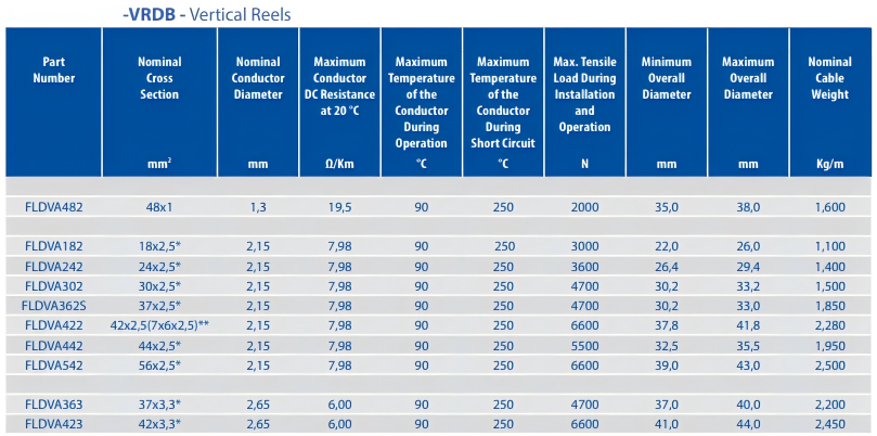
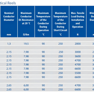
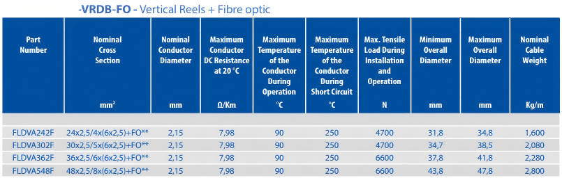
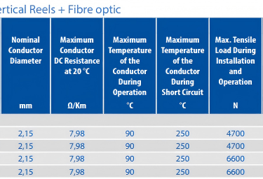
This is the parameter most frequently underspecified. The maximum tensile load combines the static weight of the suspended cable length with the dynamic increment generated during acceleration and deceleration of the spreader. Vertical cable reeling duty generates both a maximum permanent tensile load and a higher maximum dynamical tensile load during the acceleration phase. Cable data sheets publish both values; the reel and termination design must accommodate the dynamic figure, not just the static one. For a 37-core, 2.5 mm² vertical reeling cable with an overall diameter in the 30–33 mm range, typical maximum tensile loads are in the 3,600–4,700 N range depending on construction.
Operating Speed
Vertical reeling control cables are qualified for operating speeds up to 300 m/min for their primary (vertical reel) application. This is the highest speed classification in the relevant cable selection tables and reflects the duty of modern automated STS crane spreaders. When the same cable is used in a tender system application, the permissible speed reduces to 180 m/min. Confirming the actual crane operating speed against the cable's qualification limit is a straightforward but non-negotiable step.
Environmental Resistance
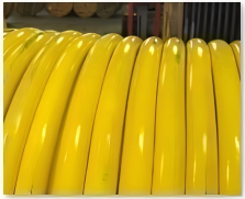
A port crane cable must resist salt spray, ozone, UV radiation, oils, hydraulic fluids, cleaning solvents, and the mechanical abrasion caused by contact with reel flanges and guide sheaves. The outer sheath compound must also have high tear resistance to withstand the tensile and flexural loads described above. Yellow-coloured elastomeric outer sheaths are commonly used in vertical reeling cables because the high-visibility colour aids inspection and maintenance, and the elastomeric compound provides superior abrasion and tear resistance compared to standard PVC constructions.
Step-by-Step Cable Selection Methodology
1. Confirm the crane type and vertical travel height. STS cranes, Goliath cranes, ship unloaders, and portal cranes all impose different nominal suspended cable lengths. Calculate the maximum suspended length to determine the static tensile load contribution from cable self-weight.
2. Define the number of control cores and cross-section required. Count all active control conductors (PLC I/O, encoder loops, safety interlocks, temperature sensors, positioning feedback) and add a minimum 10–20% spare cores for future expansion. Common cross-sections for spreader control duty are 1.0 mm², 1.5 mm², and 2.5 mm², with 2.5 mm² being the most prevalent for runs exceeding 40 m due to voltage drop considerations.
3. Determine whether integrated optical fibre is required. Where the crane specification calls for CCTV camera feeds, high-bandwidth sensor data, or Ethernet-based automation protocols, a hybrid construction incorporating integrated optical fibre units within the same vertical reeling cable eliminates the need for a separate fibre cable and the associated reel hardware. Available fibre types include multimode 62.5/125 grade index fibre and singlemode E9/125 fibre.
4. Calculate the maximum tensile load. Add the static gravitational load (cable weight per metre multiplied by maximum suspended length) to the dynamic acceleration increment specified by the crane OEM. Compare this figure against the cable data sheet's maximum dynamical tensile load during acceleration. If the required tensile load exceeds the cable rating, specify a construction with a reinforced central support element.
5. Verify the minimum bending radius against the reel drum geometry. Obtain the reel drum diameter from the mechanical design drawings. Divide the drum radius by the cable OD and confirm the result is equal to or greater than the specified minimum bending radius multiplier. If the result is below the threshold, the reel drum must be redesigned — do not attempt to compensate by selecting a different cable.
6. Confirm the operating speed classification. Match the crane's specified spreader travel speed against the cable's maximum permissible operating speed for the vertical reeling application.
7. Specify screened pairs for sensitive signal circuits where required. For encoder signals, resolver feedback, and other analogue or pulse-count circuits that are sensitive to electromagnetic interference, specify screened (individually shielded) twisted pairs within the cable assembly. This provides EMC-optimised signal integrity within the same outer sheath.
8. Review the environmental exposure profile. Confirm resistance to the specific chemicals, oils, and atmospheric conditions at the installation site. For saline marine environments, verify that the outer sheath compound is rated for ozone and UV resistance.
9. Check compliance with applicable standards. Vertical reeling control cables should comply with the relevant sections of DIN VDE 0250-813, conductor class 6 per DIN VDE EN 60228 (VDE 0295), and current-carrying capacity ratings per VDE 0298-4.
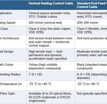
Parameter Comparison: Vertical Reeling vs. Standard Reeling Control Cable
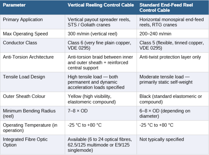
The table below illustrates the key specification differences between a cable engineered for vertical payout applications and a standard monospiral reel control cable used in end-feed or festoon configurations. Project engineers who apply standard reel cable to a vertical spreader application are making the single most common and costly selection error in this product category.
Parameter
Primary Application
Vertical payout spreader reels, STS / Goliath cranes
Horizontal monospiral end-feed reels, RTG cranes
Max Operating Speed
300 m/min (vertical reel)
200–240 m/min
Conductor Class
Class 6 (very fine plain copper, VDE 0295)
Class 5 (flexible, tinned copper, VDE 0295)
Anti-Torsion Architecture
Anti-torsion braid between inner and outer sheath + reinforced central support
Anti-twist protection layer only
Tensile Load Design
High tensile load — both permanent and dynamic acceleration loads specified
Moderate tensile load — primarily static self-weight
Outer Sheath Colour
Yellow (high visibility, elastomeric compound)
Black (standard elastomeric or compound)
Minimum Bending Radius (reel)
7–8 × OD
6–8 × OD (depending on diameter)
Operating Temperature (in operation)
-25 °C to +80 °C
-25 °C to +80 °C
Integrated Fibre Optic Option
Available (6 to 24 optical fibres, 62.5/125 multimode or E9/125 singlemode)
Not typically specified
Common Cable Selection Errors in Vertical Crane Applications
Based on field experience across port crane commissioning and maintenance projects, the following errors recur with notable frequency. Awareness of these pitfalls can prevent costly rework and unplanned downtime.
Error 1: Specifying a Horizontal Reel Cable for Vertical Duty
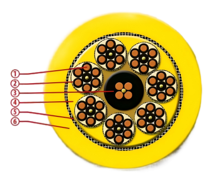
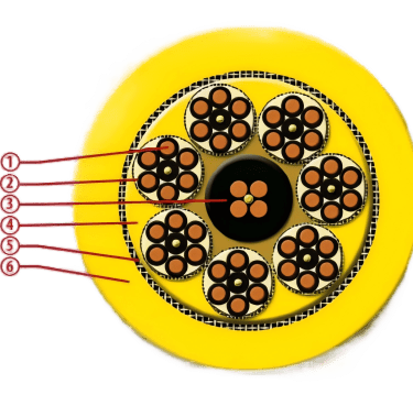
The most prevalent mistake. Standard end-feed or centre-feed power and control cables are engineered to resist torsion as a secondary characteristic. A vertical reeling cable requires a fundamentally different internal architecture — class 6 ultra-fine copper conductors, a reinforced central support element, and an anti-torsion braid embedded between the inner and outer sheath — to prevent corkscrew deformation and core breakage under sustained gravitational tensile loading.
Error 2: Ignoring the Dynamic Tensile Load
Engineers frequently size the cable based on the static weight of the suspended cable length and fail to add the dynamic acceleration increment. Modern automated STS crane spreaders can accelerate and decelerate at rates that generate tensile loads 25–40% above the static figure. If the cable is operating close to its rated tensile limit under static conditions, the first high-speed acceleration cycle may exceed the design threshold and initiate premature fatigue failure at the termination points.
Error 3: Undersizing the Reel Drum Diameter
The mechanical engineering team specifying the reel drum and the electrical team specifying the cable sometimes work in parallel without aligning on the minimum bending radius constraint. If the drum is sized for space or weight optimisation without reference to the cable OD, the resulting bending radius multiplier may fall below the required minimum, invalidating the cable warranty and initiating insulation fatigue from the first operating day.
Error 4: Failing to Account for Core Count Spare Capacity
Control system architectures evolve over the operational lifetime of a port crane, which may span 25 years or more. Specifying the exact number of cores required at commissioning, with no spare capacity, means that any automation upgrade requiring additional I/O will necessitate a cable replacement on a live crane — a complex and expensive intervention. The industry recommendation is to specify at least 15–20% additional spare cores at the initial selection stage.
Error 5: Neglecting EMC Requirements for Screened Signal Circuits
Encoder and resolver feedback signals, proximity sensor outputs, and analogue sensor circuits are susceptible to interference from the power conductors, variable-frequency drives, and radio-frequency sources present in a modern automated terminal. Specifying unscreened cores for these circuits in a multi-core vertical reeling cable can result in intermittent signal errors that are difficult to diagnose and trace. Where screened pairs are required, this must be explicitly called out in the cable specification from the outset.
Error 6: Assuming All Yellow Cables Are Equivalent
The yellow outer sheath of a vertical reeling control cable indicates a specific elastomeric compound formulated for high abrasion resistance, tear resistance, and UV stability. Some procurement teams substitute alternative yellow-sheathed cables from other product families without verifying that the internal construction, tensile rating, and anti-torsion architecture match the vertical reeling duty requirements. The outer colour alone is not a sufficient specification parameter.
Installation and Commissioning Guidance
Correct cable selection is necessary but not sufficient. The following installation practices are essential to achieving the expected service life in a vertical payout application.
• Ensure that the cable entry point, guide sheave, and reel drum are perfectly aligned along the vertical axis. Misalignment introduces rotational torque into the cable on every cycle and will defeat even the most robust anti-torsion architecture over time.
• Avoid sudden changes in bending direction. The cable must not be redirected through an acute angle within a distance of less than 20 times its overall diameter.
• Never use sheaves with a sharp or non-grooved profile. Only flat-profile or properly radiused sheave grooves should contact the cable.
• Do not overtension the cable during installation. Static pre-tension should be limited to levels consistent with the permanent tensile load rating.
• Use appropriate strain-relief termination hardware at both the crane structure and spreader connection points to ensure that tensile loads are transferred to the cable's structural element rather than to the conductor terminations.
• Inspect the outer sheath and anti-torsion braid at scheduled maintenance intervals. Early signs of braid exposure or sheath cracking indicate that the minimum bending radius or tensile load limits may be being exceeded in service.
Conclusion
Selecting the correct low voltage vertical reeling control cable for a crane spreader application is a multi-parameter engineering decision that must be approached systematically. The critical distinction between vertical reeling cables and standard reel cables lies in the combination of class 6 ultra-fine copper conductors, reinforced central support, anti-torsion braid architecture, and high-tensile elastomeric outer sheath construction — all of which are engineered specifically to resist the gravitational, torsional, and cyclic bending forces imposed by vertical payout duty.
The step-by-step methodology presented in this guide — spanning voltage class, temperature range, minimum bending radius, tensile load calculation, operating speed, screened pair requirements, and environmental resistance — provides a structured framework for both initial specification and procurement review. Equally important is awareness of the common selection errors that recur in this application category: misapplication of standard reel cables, underestimation of dynamic tensile loads, reel drum undersizing, and inadequate spare core provision.
For project engineers working on STS crane vertical reeling cable applications, Goliath crane spreader reeling cable specifications, or ship unloader vertical spreader cable procurement, adherence to this methodology will reduce the risk of premature failure and support the high availability targets demanded by modern automated container terminals.
Port crane cables | Mining cables | Reeling cables | Trailing cables | Festoon cables | Heavy-duty power cables | Medium voltage cables | Offshore crane cables | Underground mining cables | Dragline cables | Shearer cables | Container handling cables | STS crane cables | RTG cables | Mobile equipment cables | Armored cables | Flexible power cables | VFD cables | Submersible cables | Cold resistant cables | Abrasion resistant cables | Flame retardant cables | Marine environment cables | Opencast mining | Underground operations
© 2006 All rights reserved.
[INDUSTRIAL_CABLES]
INDUSTRIAL GRADE CABLE SYSTEMS | PORT & MINING SOLUTIONS
TEL: +86 153 7530 2641 |MAIL: hongjing.Wang@feichuncables.com