Main Power, Festoon, Spreader, Control, and Fiber Optic Cables — A Complete Reference for Port Engineers and Procurement Teams
Main power, festoon, spreader, control & fiber optic cables for STS cranes. A complete guide covering R-(N)TSCGEWÖU, (N)GRDGÖU and PUR spreader cable solutions.
hongjing.Wang@Feichun
6/25/202626 min read
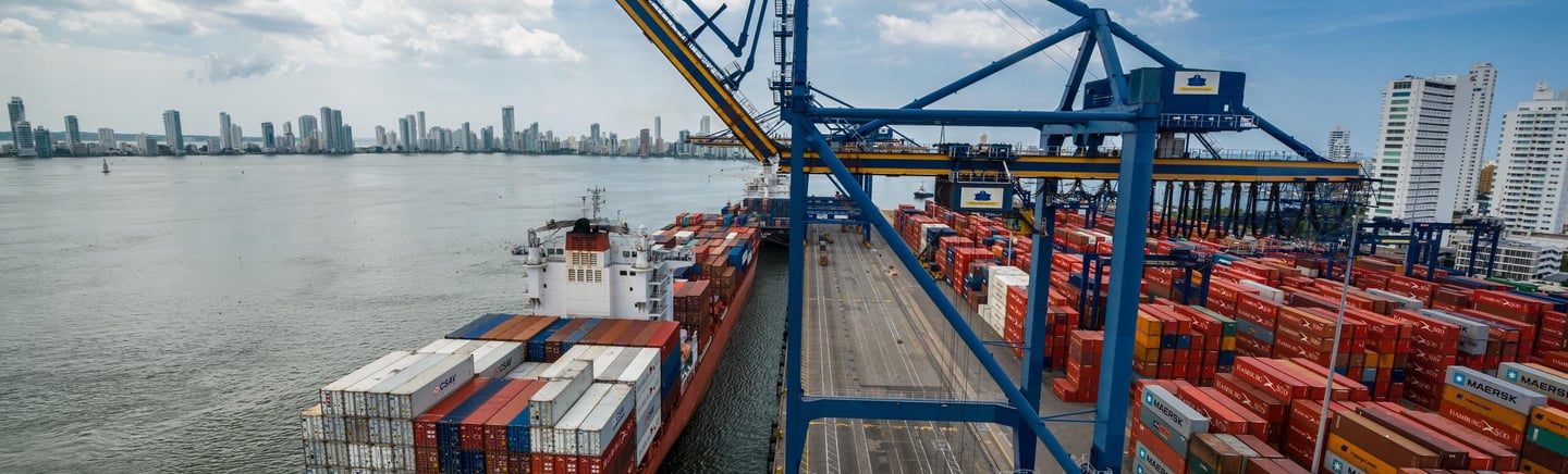

Along the quaysides of the region's busiest container terminals, from the Gulf to the Mediterranean coast, a particular machine dominates the skyline. It stands taller than the ships it serves, reaches out over their decks like a great steel arm, and lifts forty-tonne containers as though they were toys. This is the ship-to-shore crane, the single most important machine in any modern container port, and the rhythm of its movement sets the pace of the entire terminal. When these cranes run smoothly, ships are turned around quickly, berths stay productive, and the port earns its reputation. When they stop, the cost is measured not just in repair bills but in delayed vessels, congested yards, and the slow erosion of a terminal's competitive standing.
What is rarely appreciated, even by those who work around these machines every day, is how much of a ship-to-shore crane's reliability rests on its cables. A crane of this size is a moving city of electrical and electronic systems, and every one of those systems depends on cables that must carry power and data while the structure around them travels, lifts, swings, and vibrates through every working hour. The cables on a ship-to-shore crane are not passive wires; they are dynamic components subjected to some of the most demanding conditions found anywhere in heavy industry. They flex thousands of times a day, endure the corrosive bite of salt-laden coastal air, bake under intense sun, and resist the buffeting of port winds. Their selection is not a detail to be left to chance. It is a discipline that directly determines crane uptime, operational safety, and terminal productivity.
This guide is written for the engineers, procurement specialists, and project managers who carry the responsibility for that discipline. It explains what a ship-to-shore crane is, how its structure shapes the demands placed on different cables, which cable types serve which functions, what operating conditions they must survive, how they fail, and how to choose a complete cable solution rather than a single product. The intention is to build understanding patiently, so that by the end you can specify a crane's cable systems with genuine confidence and engage any supplier on equal terms.
1. Introduction: Why Cable Selection Defines Crane Performance
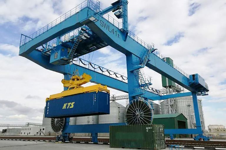
A ship-to-shore crane, almost always abbreviated to STS crane, is the large quayside crane used to load and unload containers from ocean-going vessels. It is mounted on rails that run the length of the berth, allowing it to travel along the quay to position itself over any part of a docked ship. From its elevated framework, a trolley travels back and forth along a horizontal boom that extends out over the vessel, and from that trolley a spreader descends to grip each container and lift it. In a single working cycle, the crane must move the trolley out over the ship, lower the spreader, lock onto a container, lift it clear, traverse back over the quay, and set the container down, all within seconds and repeated continuously for the duration of a vessel call. The scale and speed of this operation is what makes the STS crane such a remarkable machine, and also what makes its cables work so hard.
The environment in which these cranes operate is among the harshest that any industrial equipment must endure. Ports are coastal by definition, which means the air carries salt spray that attacks materials relentlessly. The cranes are fully exposed to the sun, so every cable on the structure absorbs ultraviolet radiation throughout the daylight hours, year after year. The wind off the water can be strong and gusty, setting up sway and vibration in any cable that hangs or runs in the open. And underlying all of this is the constant mechanical activity of a machine that travels long distances along the quay and moves its trolley at high speed across the boom. Long travel, high speed, salt spray, ultraviolet exposure, and wind combine to create a set of conditions that would quickly destroy ordinary cables.
The consequence of getting cable selection wrong is severe and immediate. Unlike many components that degrade gracefully and give ample warning, a failed cable can stop a crane instantly. A reeling cable that cracks and admits moisture can cause an electrical fault that trips the crane offline. A festoon cable that twists and fatigues can interrupt control signals at a critical moment. A spreader cable that breaks under repeated bending can leave the crane unable to handle containers at all. Each of these failures translates directly into crane downtime, and in a busy terminal, crane downtime is one of the most expensive things that can happen. It can also create safety hazards, because cables carry not only power but the control and interlock signals that keep the machine operating within safe limits. Cable failure, in short, can directly affect crane uptime, safety, and terminal productivity, which is precisely why cable selection deserves to be treated as a serious engineering decision rather than a routine purchase.
To make that decision well, it helps to recognize that an STS crane does not use one cable but a family of cables, each suited to a different part of the machine and a different kind of duty. The main categories are the main power reeling cable that supplies the crane with electricity, the festoon cable that serves the moving trolley, the spreader cable that feeds the most dynamic part of the machine, the control cable that carries operating and safety signals, and the fiber optic cable that handles high-speed data and communication. Understanding each of these, and how they fit together, is the foundation of a sound cable solution.
2. STS Crane Structure: How the Machine Shapes the Cable Demands
To understand why each cable on an STS crane is built the way it is, one must first understand the structure of the crane and how its parts move. The demands placed on a cable are determined by where it sits on the machine and what kind of motion it must accommodate. Four main structural elements define these demands: the boom, the gantry, the trolley, and the spreader.
The boom is the long horizontal arm that extends out over the vessel, defining the working reach of the crane. It is the boom that allows the trolley and spreader to travel out over the ship's deck and reach containers stowed across the full width of the vessel. Many booms can be raised to a near-vertical position when the crane is not working, to clear the airspace above a departing or arriving ship, and lowered into the horizontal working position when operations begin. Cables that run along or near the boom must therefore tolerate not only the vibration and outdoor exposure that come with the territory, but in many cases the movement of the boom itself as it is raised and lowered. A cable in this zone lives entirely in the open air, fully exposed to sun, salt, and wind, and must be built to withstand that exposure for years without its sheath degrading.
The gantry is the supporting structure of the crane, the great framework of steel legs and beams that carries the entire machine and rests on the rails along the quay. It is the gantry that enables the crane to travel along the berth, moving from one position to another to align with different holds of a vessel or to clear a berth for another ship. This gantry travel is the long-distance motion of the crane, and it is what the main power reeling cable must accommodate as it feeds electricity to the moving machine. Gantry movement, because it covers long distances and involves the full power demand of the crane, requires durable and robust power and control cable systems capable of being wound and unwound repeatedly as the crane travels.
The trolley is the unit that travels back and forth along the boom, carrying the lifting machinery and the connection to the spreader below. It is the trolley's rapid traverse along the boom that gives the crane its working speed, moving out over the ship to pick up a container and back over the quay to release it, cycle after cycle. The trolley carries power, control, and data-related cable systems with it as it moves, and these cables must travel with the trolley along its full path. The critical point about the trolley is its speed: modern cranes move their trolleys very fast to maximize the number of container moves per hour, and high trolley speed dramatically increases the wear and fatigue risk on the cables that serve it. Every traverse flexes these cables, and at high speed, with many cycles per hour, the cumulative flexing is enormous. This is why the cable systems serving the trolley must be designed specifically for high-cycle dynamic service.
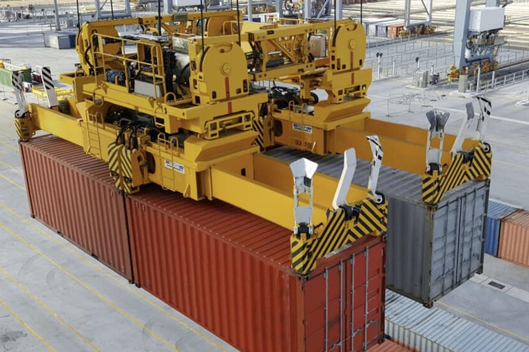
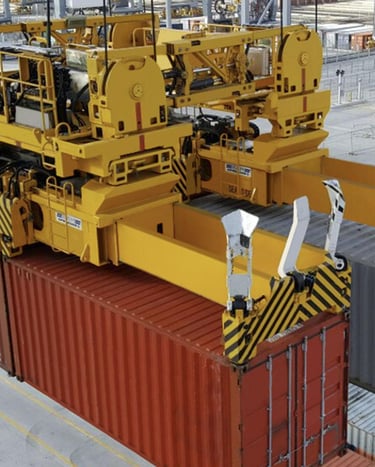
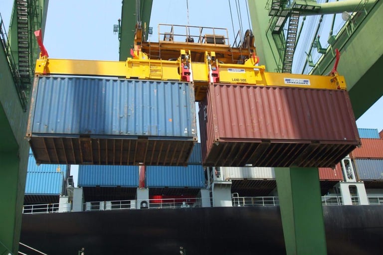
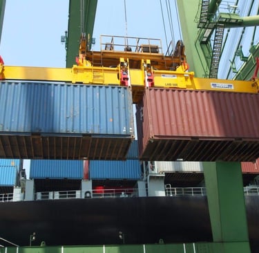
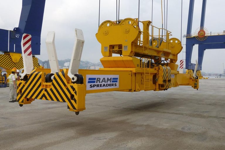
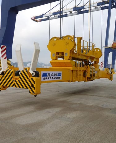
The spreader is the device at the very bottom of the lifting chain, the frame that actually grips the container. It descends from the trolley, locks onto the four corner castings of a container with twist-lock pins, lifts it, and releases it at the destination. The spreader operates in the most dynamic part of the entire crane, moving vertically up and down with every lift while also being subject to swing and sway. The cabling that serves the spreader must therefore be flexible, lightweight, and highly dynamic, capable of coiling and extending with the spreader's vertical motion and tolerating the constant movement without fatigue. Spreader cables frequently combine several functions in one, carrying power to operate the twist-locks and other spreader mechanisms, control signals to coordinate their operation, and sometimes fiber optic cores for data, all within a single compact and flexible cable. The spreader, in short, places the most severe combined demands of any zone on the crane, and its cabling is correspondingly specialized.
Seen as a whole, the crane presents a hierarchy of motion. The gantry provides slow, long-distance travel along the quay. The trolley provides fast, repetitive traverse along the boom. The spreader provides rapid vertical motion with swing and sway. Each kind of motion calls for a different cable solution, and the art of cabling an STS crane lies in matching the right cable to each zone of movement.
3. Cable Types on STS Cranes: A Solution for Every Zone
With the structure understood, we can examine each of the main cable types in turn, considering what it does, what it must withstand, and what kind of cable is appropriate.
Main Power Reeling Cable
The main power reeling cable is the lifeline of the crane, the cable that supplies the high electrical power needed to run all of the crane's motors and systems. As the gantry travels along the quay, this cable is wound onto and off a motorized reel, paying out as the crane moves away from its supply point and drawing back in as it returns. It carries the full electrical load of the machine and must do so reliably across long travel distances and through countless winding cycles.
For high-power cranes, this main supply is most often provided at medium voltage rather than low voltage, with common ratings such as 6 kilovolts and 10 kilovolts. The reason for choosing medium voltage is rooted in basic electrical physics. A given amount of power can be delivered either as a high current at low voltage or as a lower current at medium voltage, and for a high-power, long-travel machine the medium voltage approach is decisively better. By supplying the crane at medium voltage, the current required to deliver the necessary power is reduced, because power equals voltage multiplied by current. A lower current means less voltage drop along the long cable run from the supply point to the moving crane, which matters greatly when the crane may be hundreds of meters from its supply at the far end of its travel. It also means a smaller conductor cross-section for the same power, producing a lighter and more flexible cable that is easier for the reel to handle, and it reduces the resistive heating losses in the cable, improving efficiency and reducing thermal stress. For all these reasons, medium voltage reeling cable is generally preferred for high-power port cranes, and it is the standard choice for the main power supply of large STS cranes.
The appropriate cable for this duty is R-(N)TSCGEWÖU, a flexible medium voltage reeling cable engineered specifically for the dynamic stresses of reel operation. For applications requiring additional structural support to withstand particularly severe mechanical stress, the reinforced variant R-(N)TSKCGEWÖU is available, the additional K in its designation indicating the structural reinforcement. Both are built from finely stranded flexible copper conductors, special rubber insulation with semi-conductive field control layers, an anti-torsion braid, and a tough multi-layer outer sheath, all designed to survive the bending, twisting, and tension of continuous reeling service while delivering medium voltage power reliably.
Trolley Festoon Cable
The trolley, as we have seen, travels rapidly back and forth along the boom, and the cables that serve it must travel with it. The most common method of managing these traveling cables is the festoon system, in which the cable is suspended from a series of trolleys or carriers running on a track or wire above or alongside the boom. As the crane trolley moves, the festoon carriers gather together or spread apart like the folds of a curtain, allowing the cable to extend and retract smoothly while remaining supported along its length. This festoon arrangement is a proven and widely used solution for managing the power, control, and data cables that must accompany the moving trolley.
A festoon cable faces a distinctive combination of stresses. It must handle repeated bending as it gathers and extends with every traverse of the trolley, lateral motion as the festoon folds open and closed, and the suspended travel that comes from hanging in the festoon system rather than resting on a surface. Because the trolley moves quickly and frequently, the festoon cable accumulates an enormous number of bending cycles over its life, and it must be built to endure this without fatigue. Quality festoon cables are designed and rated for exactly this duty, with finely stranded flexible conductors, robust elastomer insulation and sheathing, and in many cases a copper braid screen to provide electromagnetic protection for sensitive control and data signals. Such cables are typically rated for travel speeds in festoon systems of up to two hundred and forty meters per minute, which comfortably covers the trolley speeds of even fast modern cranes, and they are built to withstand the high mechanical stresses and frequent bending that festoon operation imposes.
The appropriate cables for festoon duty are the established festoon and chain cable families (N)GRDGÖU and the screened (N)GRDGCGÖU, designed for material handling and crane applications. These are flexible low voltage power and control cables rated at 0.6/1 kilovolt, suitable for use in dry, damp, or wet conditions and built specifically for high mechanical stress and frequent bending. The screened (N)GRDGCGÖU variant adds a tinned copper wire braid, typically covering around eighty percent of the surface, which protects control and data signals from interference, an increasingly important feature as cranes become more automated and carry more sensitive electronics. The right cable should be selected based on the trolley travel speed, the expected bending cycle frequency, and the environmental exposure of the particular installation, ensuring that the cable's ratings comfortably exceed the demands of the application.
Spreader Cable
The spreader cable operates in the most dynamic part of the entire crane, descending and retracting with the spreader through every lifting cycle and enduring the swing and sway that come with handling suspended loads. This is the cable that experiences the most severe combination of flexing, motion, and exposure, and it must be built to a correspondingly high standard.
For spreader applications, a cable with a polyurethane outer sheath, commonly abbreviated as PUR, is often preferred. Polyurethane offers an excellent combination of properties that suit the spreader environment particularly well: strong resistance to abrasion as the cable rubs against guides and surfaces during its constant motion, high flexibility that allows it to coil and extend without fatigue, and good outdoor durability against the sun, salt, and weather of the coastal port. A polyurethane-sheathed cable can take the punishment of spreader duty while remaining flexible and compact, which is essential when the cable must coil neatly and add as little weight as possible to the moving spreader.
Beyond the sheath material, a spreader cable typically needs a high flex life, meaning the ability to endure a very large number of bending cycles before any sign of fatigue, together with a compact construction that keeps weight and bulk to a minimum. Increasingly, spreader cables also incorporate optional integrated fiber optic cores, allowing high-speed data to travel down to the spreader alongside the power and control conductors. This integration supports the sensors, cameras, and automated systems that modern spreaders carry, all within a single cable that simplifies the installation. The right solution for this zone can be described simply as a polyurethane-sheathed spreader cable with optional fiber optic cores and a high-flex construction, purpose-built for the container spreader systems of STS cranes.
Control Cable
Running throughout the crane, alongside the power cables, are the control cables that carry the signals for operation, positioning, and safety. These cables convey the commands that tell the crane's systems what to do, the feedback that reports the position of the trolley and spreader, and the critical interlock signals that prevent unsafe operations from occurring. Without reliable control cabling, a crane cannot function safely or precisely.
Control cables on an STS crane share many of the same demands as the power cables, because they travel through the same moving zones, the gantry, the trolley festoon, and the spreader. They must be flexible to accommodate this movement, oil resistant to survive the lubricants and hydraulic fluids present around the machinery, and suitable for repeated movement without fatigue. In practice, control cables are very often paired with power and data cables within the same moving cable system, sharing a festoon or reel arrangement, which means they must match the mechanical performance of the power cables they accompany. A control cable that fatigues faster than the power cable beside it becomes the weak link that brings down the whole system. For this reason, control cables for crane duty are built to the same high standards of flexibility, environmental resistance, and fatigue life as the power cables they serve alongside, frequently with copper braid screening to protect the signals from the electrical noise generated by the crane's powerful motors.
Fiber Optic Cable
The final category, and an increasingly important one, is the fiber optic cable used for high-speed communication, automation, and data exchange. As ports modernize and automate, the volume and importance of data flowing to and from the crane grows continuously. Control systems exchange information in real time, diagnostic systems monitor the health of the machine, cameras and sensors feed images and measurements to operators and automated systems, and remote monitoring links connect the crane to the terminal's central management systems. All of this depends on stable, high-bandwidth communication, and fiber optic transmission is the technology of choice for delivering it.
Modern STS cranes therefore often require fiber optic communication for their control systems, their diagnostics, and their automation functions. Fiber offers enormous bandwidth, immunity to the electromagnetic interference that fills the electrical environment of a crane, and the ability to carry data over long distances without degradation. In many installations, the most practical approach is to integrate fiber optic cores directly into the power or control cables, so that data and power move together through the same cable system. This integrated approach is particularly useful in the moving zones of the crane, where running a separate fiber cable through the festoon or reel alongside the power cable would add complexity. By combining power and data in one cable, the installation is simplified and the data link enjoys the same robust mechanical protection as the power conductors. Integrated fiber optic versions are thus especially valuable wherever power and data need to move together through the dynamic parts of the crane.
4. Operating Conditions: The Environment That Tests Every Cable
Having surveyed the cable types, we now turn to the conditions they must survive. The operating environment of an STS crane is uniquely demanding, and understanding each environmental factor helps explain why crane cables are built to such exacting standards.
Long travel is the first and most fundamental condition. STS cranes routinely travel long distances along the quay as they reposition along a berth or move between berths, and the main power reeling cable must accommodate this entire travel range. Over a long travel path, the cable is wound and unwound through many cycles, and each cycle imposes mechanical stress. The cumulative effect of this repeated winding over a long travel distance is substantial, and it is why the reeling cable must be built for endurance, with the fatigue resistance to survive years of continuous winding without degradation. Long travel also means that voltage drop becomes significant if the supply is not at an appropriate voltage, reinforcing the case for medium voltage main power discussed earlier.
High-speed trolley operation is the second major condition. The drive to maximize container moves per hour pushes crane designers toward ever-faster trolley speeds, and fast trolley movement directly increases the flexing frequency and dynamic loading on the cables that serve it. Each traverse of the trolley flexes the festoon and spreader cables, and at high speed with many traverses per hour, the number of flex cycles accumulates rapidly. High-speed operation therefore demands cable designs with strong fatigue resistance, built from finely stranded conductors and resilient sheath materials that can endure this relentless flexing. A cable that would last for years at modest speeds might fail far sooner under the punishing cycle count of a fast modern crane, which is why matching the cable's flex rating to the trolley speed is essential.
Salt spray is the signature challenge of the coastal port environment. Because ports sit at the water's edge, the air they breathe is laden with salt, and this salt-laden air settles on every surface of the crane, including its cables. Salt spray accelerates the aging of cable jackets, attacking the polymer materials and shortening their service life. It promotes corrosion-related damage wherever metal is exposed or moisture can penetrate, and it can compromise the sealing of cable glands and terminations. A cable destined for port service must therefore be built from sheath materials specifically resistant to this corrosive marine atmosphere, and its terminations must be sealed against salt and moisture ingress. The relentless presence of salt is one of the defining reasons that ordinary cables fail quickly in ports while purpose-built crane cables endure.
Ultraviolet exposure is the second great environmental challenge. STS cranes stand fully exposed to the sun, and their outdoor cables absorb ultraviolet radiation throughout every daylight hour for the entire life of the installation. Ultraviolet light degrades many polymer materials, causing them to become brittle, crack, and lose their protective properties over time. A crane cable must therefore resist sunlight and long-term weathering, with sheath materials formulated specifically for ultraviolet resistance. This is especially important for the festoon and spreader cables that hang and move in the open air, fully exposed to the sun, where the combination of ultraviolet exposure and constant flexing places a double demand on the sheath material.
High wind completes the picture of environmental stress. Ports are often windy places, and the wind off the water can be strong and gusty. Wind increases the sway, vibration, and uncontrolled movement of any cable that hangs or runs in the open, and this is particularly true of festoon cables suspended along the boom and spreader cables hanging from the trolley. Wind-induced sway and vibration accelerate abrasion as cables rub against guides and structures, and they aggravate the twisting damage that festoon and spreader cables are already prone to. A cable in a windy port environment must therefore be robust against abrasion and twisting, and the cable management system must be designed to control sway and keep the cable's movement within safe bounds. Wind is the factor most easily overlooked in cable selection, yet it can be a significant contributor to cable wear in exposed crane zones.
Taken together, these five conditions, long travel, high-speed trolley operation, salt spray, ultraviolet exposure, and high wind, define an environment that punishes any cable not specifically built to withstand it. The cables that survive and perform reliably in STS crane service are those engineered from the outset for this precise combination of mechanical and environmental stress.
5. Common Failure Modes: Learning From How Cables Fail
The surest way to appreciate what makes a good crane cable is to study how crane cables fail. Each failure mode reveals a specific weakness and points toward a specific defense. Three failure modes are particularly characteristic of STS crane cabling.
Festoon cable twist is a failure that arises when the motion of a festoon cable is not properly guided. In a well-designed festoon system, the cable gathers and extends in a controlled plane, bending but not twisting. When the system is poorly designed or maintained, however, or when wind and uncontrolled movement come into play, the cable can begin to twist about its own axis as it travels. This twisting is damaging because it works the internal structure of the cable in a way that simple bending does not. Repeated twisting can lead to conductor fatigue, as the internal copper strands are stressed in ways they were not designed to handle, and to deformation of the jacket as the sheath is wrung and distorted. Over time, twist damage degrades the cable from within, and the festoon cable that twists is on a path toward eventual failure. The defenses against this failure are a well-designed festoon system that guides the cable cleanly, a cable with a torsional rating appropriate to the application, often specified as a permissible twist of around twenty-five degrees per meter of length, and attention to the geometry of directional changes, with adequate distance allowed for any S-type changes of direction in the cable's path.
Spreader cable breakage is the failure of the cable serving the most dynamic part of the crane. Because spreader cables are subject to the highest dynamic stress of any cable on the machine, descending and retracting with every lift while enduring swing and sway, they are the most prone to outright breakage. This breakage is most often caused by repeated bending that gradually fatigues the conductors until they fail, by tension spikes that occur when the spreader's motion is sudden or when the cable is snagged or shock-loaded, or by poor strain relief at the points where the cable connects to the spreader and the trolley. Strain relief is particularly important, because a cable that is not properly supported at its terminations will concentrate all the bending stress at those points, leading to fatigue and breakage precisely where the cable enters its connections. The defenses against spreader cable breakage are a cable with a high flex life and appropriate flexibility, a compact and lightweight construction that reduces the inertial loads during motion, a polyurethane sheath that resists abrasion and remains flexible, and careful attention to strain relief at every termination so that bending stress is distributed rather than concentrated.
Reeling cable wear is the gradual degradation of the main power reeling cable through the mechanical action of reel operation. Reeling cable wear arises from the drum winding that repeatedly bends the cable around the reel, from the abrasion that occurs as the cable rubs against itself and against guides during winding, and from the repeated mechanical cycles that accumulate over the cable's working life. This wear typically manifests first as surface wear on the sheath, which over time can progress to jacket cracking. Once the jacket cracks, the protective barrier is breached, moisture and contaminants can penetrate, and the path is opened toward eventual electrical failure as the insulation is compromised. The defenses against reeling cable wear are a cable specifically built for reeling duty with an abrasion-resistant sheath, a reel and drum system sized to respect the cable's minimum bending radius so that the cable is never bent too tightly, and a level wind or other mechanism that ensures the cable winds evenly without the localized pressure and abrasion that uneven stacking would cause.
The common thread running through these failure modes is that they are overwhelmingly mechanical in origin, even when the final symptom is electrical. The festoon cable twists, the spreader cable is bent and shock-loaded, the reeling cable is worn by winding and abrasion, and only after this mechanical degradation does the electrical failure follow. This is the central lesson of crane cable failure analysis: the mechanical specification of a crane cable, its flexibility, its fatigue life, its torsional rating, its abrasion resistance, deserves at least as much attention as its electrical rating. A cable chosen to withstand the mechanical reality of its zone will, in the great majority of cases, also deliver the electrical reliability the crane depends upon.
6. Recommended Cable Solutions: Matching Cable to Function
Drawing together the analysis above, we can set out a coherent set of cable solutions for the main functions of an STS crane. The principle throughout is to match each cable to the specific demands of its zone.
For the medium voltage main power supply, the recommended solution is R-(N)TSCGEWÖU, a flexible medium voltage reeling cable available in the relevant ratings such as 6/10 kilovolts and 8.7/15 kilovolts to suit the power requirements of the crane. This cable is purpose-built for the reeling duty of the gantry's long travel, combining medium voltage electrical capability with the flexibility, fatigue resistance, and abrasion resistance that reeling service demands. Where the mechanical stress is especially severe and additional structural support is needed, the reinforced variant R-(N)TSKCGEWÖU provides extra strength to withstand the most demanding conditions. The choice between R-(N)TSCGEWÖU and the reinforced R-(N)TSKCGEWÖU depends on the specific mechanical severity of the installation, including travel distance, reeling speed, and the geometry of the reel system.
For the festoon system serving the trolley, the recommended solution is (N)GRDGÖU, or the screened (N)GRDGCGÖU where electromagnetic protection of control and data signals is required. These are flexible low voltage cables rated at 0.6/1 kilovolt, built specifically for the repeated bending, lateral motion, and suspended travel of festoon operation, and rated for festoon travel speeds up to two hundred and forty meters per minute. The screened (N)GRDGCGÖU, with its tinned copper wire braid covering around eighty percent of the cable surface, is the appropriate choice wherever the festoon cable carries control or data signals that must be protected from the electrical noise of the crane's motors. Specifying the practical, readily available (N)GRDGÖU and (N)GRDGCGÖU families, rather than searching for an obscure or hard-to-source model designation, makes the festoon cable for the STS crane trolley easy to source, with the specific construction and core configuration selected to match the power, control, and data needs of the particular crane.
For the spreader application, the recommended solution is a polyurethane-sheathed spreader cable with optional fiber optic cores and a high-flex construction. The polyurethane sheath provides the abrasion resistance, flexibility, and outdoor durability that the spreader's severe dynamic environment demands, while the high-flex construction ensures a long fatigue life through the many bending cycles of continuous lifting. The optional fiber optic cores allow data from the spreader's sensors and systems to travel up to the crane's control systems within the same cable. In product terms, this can be specified simply as a polyurethane spreader cable for STS crane container spreader systems, with fiber optic integration where the application requires data transmission to and from the spreader.
For control and data, the recommended approach is to incorporate flexible control cable and fiber optic cable as integral parts of the overall crane cable solution rather than treating them as afterthoughts. The control cables should match the flexibility, oil resistance, and fatigue performance of the power cables they accompany, with screening where signal protection is needed. The fiber optic provision should be planned according to the crane's automation and communication requirements, whether as standalone fiber cables or as fiber cores integrated into the power and control cables in the moving zones. Treating control and data cabling as a designed part of the whole, rather than a collection of separate purchases, produces a more reliable and more maintainable installation.
The essential point is that no single cable serves an STS crane. The crane requires a coordinated set of cables, each matched to its zone, and the quality of the overall solution depends on every one of them being correctly specified. A perfect main power cable cannot compensate for a festoon cable that fatigues, and an excellent spreader cable cannot make up for a control cable that fails under vibration. The solution is the system, not any single part of it.
7. Why These Solutions Work: The Logic of the Complete System
It is worth stepping back to articulate why this particular combination of cable solutions is the right one. An STS crane needs three things from its cabling simultaneously: high power transfer to run its powerful motors and systems, mechanical flexibility to accommodate the constant motion of its moving parts, and environmental resistance to survive the salt, sun, and wind of the coastal port. No single cable type delivers all three in equal measure for every zone of the machine, which is why the solution is a coordinated set of specialized cables rather than a single universal product.
Medium voltage reeling cable is the right choice for the main power supply because it addresses the specific challenge of delivering high power over a long, moving travel path. The medium voltage rating keeps the current and therefore the voltage drop manageable over the gantry's long travel, the reeling construction provides the flexibility and fatigue resistance needed for continuous winding, and the robust sheath survives the port environment. For long-travel, high-load systems, no other cable type matches the combination of qualities that medium voltage reeling cable provides.
Festoon cable is the right choice for the trolley because it is purpose-built for the controlled suspended movement that festoon systems require. The trolley moves quickly and frequently, and the festoon cable's flexible construction and high bending-cycle endurance are precisely matched to this repetitive traversing motion. Where control and data signals must be protected, the screened version adds electromagnetic shielding without sacrificing the flexibility the application demands. The festoon cable suits the trolley because it is designed for exactly the kind of suspended, frequently bending motion that the trolley imposes.
Polyurethane spreader cables are the right choice for the spreader because they meet the compact, high-cycle, high-abrasion demands of the most dynamic zone on the crane. The polyurethane sheath resists the abrasion of constant motion and the weathering of outdoor exposure, the high-flex construction endures the relentless bending of continuous lifting, and the compact form keeps weight low so the cable can coil and extend cleanly with the spreader. For an application defined by severe, repetitive, abrasive motion, the polyurethane spreader cable is the natural solution.
Finally, fiber optic integration is the right choice for data because it supports the smart-port automation and remote monitoring that increasingly define competitive terminals. As ports automate, the demand for high-bandwidth, interference-immune data transmission grows, and fiber delivers it. Integrating fiber into the moving cable systems allows data to travel with power and control through the dynamic zones of the crane, supporting the sensors, cameras, and control systems that modern automated operations require. Fiber integration is what allows the cabling solution to serve not just today's crane but the increasingly automated crane of the future.
The logic of the complete system, then, is that each cable solves the problem of its own zone, and together they form a cabling solution that delivers power, flexibility, environmental resistance, and data capability across the entire machine. This is why the combination works, and why specifying it as a coordinated whole produces a far more reliable crane than assembling cables piecemeal.
8. Key Considerations for Specification and Sourcing
For those preparing specifications or comparing offers, a number of practical considerations follow from everything above. When specifying the main power reeling cable, establish the system voltage first, then determine the conductor size from the crane's power demand and the local ambient temperature, remembering that the high ambient temperatures common across much of the region may require the cable's current capacity to be assessed carefully. Confirm that the reel drum diameter respects the cable's minimum bending radius, and verify that the cable's reeling speed and tensile ratings cover the demands of the gantry travel.
When specifying festoon cabling, match the cable's travel speed rating to the trolley speed, ensure the bending-cycle endurance suits the expected duty, and choose the screened version wherever control or data signals are present. Confirm that the cable's voltage rating, typically 0.6/1 kilovolt for festoon power and control cables, suits the trolley's electrical needs, and check that the core configuration provides for all the power, control, and data circuits the trolley requires.
When specifying spreader cabling, prioritize flex life, abrasion resistance, and compactness, confirm that the polyurethane sheath suits the outdoor coastal environment, and decide whether integrated fiber optic cores are needed for the spreader's data requirements. Pay particular attention to strain relief at the terminations, since this is where spreader cables most often fail.
For control and fiber optic cabling, plan these as part of the integrated solution from the outset, matching the control cables' mechanical performance to the power cables they accompany and provisioning fiber according to the crane's automation roadmap. Throughout, verify conformity to the relevant standards and to any project-specific requirements, which large infrastructure projects in the region frequently impose on top of the baseline standards. A specification that addresses all of these points produces a cable solution that performs reliably and avoids the costly disputes that arise when requirements are discovered only after installation.
For those concerned with discoverability and clear communication in technical documentation and procurement, the natural terms that describe these solutions include STS crane cable, STS crane reeling cable, STS crane festoon cable, STS crane spreader cable, medium voltage crane cable, 6 kilovolt crane cable, 10 kilovolt reeling cable, port crane cable, container crane cable, and crane fiber optic cable. Using clear, established terminology of this kind, rather than obscure model designations, makes specifications easier to source against and easier for all parties to understand.
9. Conclusion: A Complete Solution for a Complex Machine
The ship-to-shore crane is one of the most demanding machines in all of heavy industry, and its cabling is one of the most demanding applications any cable must serve. We have seen that an STS crane requires not a single cable but a complete cable solution, in which main power, trolley, spreader, control, and fiber optic cables each serve a different zone of motion and a different function. The main power reeling cable feeds the long-traveling gantry at medium voltage; the festoon cable serves the fast-moving trolley with controlled suspended motion; the spreader cable endures the most severe dynamic stress in a compact, abrasion-resistant, polyurethane-sheathed form; the control cable carries the signals that keep the machine operating safely and precisely; and the fiber optic cable, often integrated into the moving cables, delivers the data that modern automated terminals depend upon.
Each of these cables serves a different motion zone, and the demands of each zone determine the right cable for it. The gantry's long, slow travel calls for a robust reeling cable. The trolley's fast, repetitive traverse calls for a flexible festoon cable with high bending endurance. The spreader's rapid vertical motion with swing and sway calls for the most flexible and abrasion-resistant cable of all. And the crane's growing appetite for data calls for fiber optic communication woven through the whole. The best solution for any given crane depends on the specifics: the travel distance of the gantry, the speed of the trolley, the severity of the coastal environment, and the mechanical stresses of the particular installation.
What unites the whole is the recognition that crane cabling is a system, designed and specified as a coordinated whole, with each cable matched to its zone and the entire solution built to survive the salt, sun, wind, and ceaseless motion of the port. The medium voltage reeling cable R-(N)TSCGEWÖU (with its reinforced counterpart R-(N)TSKCGEWÖU), the festoon cables (N)GRDGÖU and (N)GRDGCGÖU designed for trolley duty, and the polyurethane spreader cables built for high-cycle service together form a proven foundation for the cabling of modern STS cranes. Specified with care, matched to the application, and verified against the relevant standards, these solutions deliver the quiet, invisible reliability that keeps cranes running and terminals productive.
In an industry where the turnaround of every vessel matters and the cost of a stopped crane is measured in hours of lost productivity, the cables that never fail are worth far more than their modest share of the crane's cost. Choosing those cables, with knowledge of the machine, the environment, and the demands of each zone, is the purpose this guide has set out to serve. The crane is the visible giant on the skyline; the cables are the unseen system that keeps it moving. Specify them well, and the giant works tirelessly. Specify them poorly, and the giant falls silent. The difference, more often than anyone realizes, comes down to the cable.
Port crane cables | Mining cables | Reeling cables | Trailing cables | Festoon cables | Heavy-duty power cables | Medium voltage cables | Offshore crane cables | Underground mining cables | Dragline cables | Shearer cables | Container handling cables | STS crane cables | RTG cables | Mobile equipment cables | Armored cables | Flexible power cables | VFD cables | Submersible cables | Cold resistant cables | Abrasion resistant cables | Flame retardant cables | Marine environment cables | Opencast mining | Underground operations
© 2006 All rights reserved.
[INDUSTRIAL_CABLES]
INDUSTRIAL GRADE CABLE SYSTEMS | PORT & MINING SOLUTIONS
TEL: +86 153 7530 2641 |MAIL: hongjing.Wang@feichuncables.com