
Medium Voltage Reeling Cable Selection Guide for Ports and Mining
How to select MV reeling cable for ports and mining: voltage, bending radius, tension, torsion, standards, and NTSCGEWOEU / R-(N)TSCGEWOEU cable solutions.
hongjing.Wang@Feichun
6/25/202628 min read
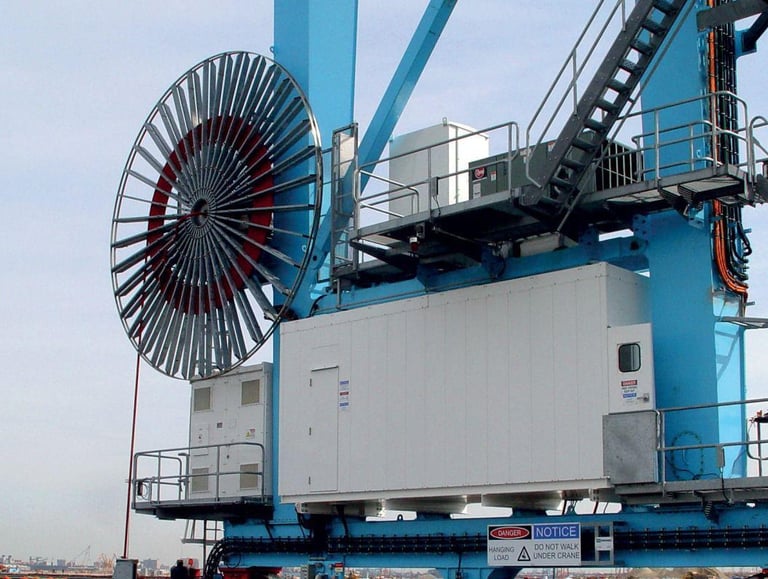
A Practical Reference for Engineers, Procurement Teams, and Project Planners
In the great ports of the Gulf and the Red Sea, in the phosphate and copper operations of the wider region, and across the heavy material handling sites that keep regional trade and industry moving, there is a quiet component that almost never receives attention until the moment it fails. It is not the crane itself, nor the motor that drives it, nor the control system that coordinates the whole operation. It is the cable that feeds power to the machine while the machine is in constant motion. When that cable is chosen well, it disappears into the background and does its work for years. When it is chosen poorly, it becomes the single point of failure that brings an entire terminal or mine face to a standstill.
This guide is written for the people who carry the responsibility for that decision. Whether you are an electrical engineer specifying equipment for a new container terminal, a procurement manager comparing offers for an open-cast mining expansion, or a maintenance leader trying to understand why a previous cable installation did not last as long as expected, the intention here is to give you a clear, complete, and honest picture of what medium voltage reeling cable is, why it behaves the way it does, and how to choose the right one for your specific application.
We will move deliberately, from foundational concepts toward the finer points of selection, so that by the end you will be able to read a technical specification with confidence and ask the right questions of any supplier. The aim is not to rush you toward a conclusion, but to build understanding piece by piece, the way a good engineering decision should always be built.
1. Introduction: The Cable That Moves With the Machine
Medium voltage reeling cable is a specialized type of flexible power cable designed to deliver electrical energy to equipment that is in continuous or frequent motion. Unlike the fixed cables buried in trenches or fastened to walls inside a building, a reeling cable spends its working life being wound and unwound, bent and straightened, twisted and released, often many thousands of times across its service life. It is, in the truest sense, a cable that travels with the machine it powers.
The word "reeling" points directly to how the cable is managed. As a large machine moves along its travel path, a reel or drum mounted on the machine pays the cable out or draws it back in, keeping it organized and under controlled tension. This constant winding and unwinding is exactly what an ordinary power cable is not built to survive. The mechanical demands are relentless: frequent bending around the drum, torsional stress as the cable twists during the reeling motion, dynamic tensile loads as the cable is pulled along, and the repeated flexing that accompanies every change of direction.
Because of these demands, reeling cable is engineered from the inside out for dynamic power transmission. Every layer, from the conductor at its heart to the protective outer sheath, is selected and constructed with movement in mind. The conductor is made of very finely stranded copper so that it can flex without breaking. The insulation is a special rubber compound chosen for its combination of electrical strength and mechanical resilience. The sheath system is reinforced to resist abrasion, tearing, and the twisting forces that would quickly destroy a lesser cable.
These cables are found wherever heavy electrical equipment must move while drawing significant power. The most prominent application areas are seaports, mining operations, and bulk material handling facilities. In ports, they feed the towering cranes that load and unload container ships and the machines that move bulk cargo such as grain, ore, and coal. In mining, they power the excavators, crushers, and reclaimers that operate across open-cast sites and underground galleries. In bulk handling, they supply the stackers, reclaimers, and shiploaders that form the backbone of any large export terminal.
The "medium voltage" designation refers to the operating voltage class of the cable, which sits above ordinary low voltage but below the high voltage levels used for long-distance transmission. Common voltage ranges encountered in this category include 3.3 kilovolts, 6 kilovolts, 10 kilovolts, and 15 kilovolts, with some applications extending to 20 kilovolts and beyond. The choice of voltage is not arbitrary; as we will explore later, supplying heavy mobile equipment at medium voltage rather than low voltage brings important practical advantages in efficiency and cable size. For now, it is enough to understand that this family of cables occupies a specific and demanding niche: high power, constant motion, and harsh industrial environments, all at the same time.
2. What Is a Medium Voltage Reeling Cable
Having introduced the concept, let us define it precisely. A medium voltage reeling cable is a flexible medium voltage power cable specifically designed for use with reel systems, drum systems, or other cable management arrangements that store and deploy the cable as a machine moves. The defining characteristic is the union of two qualities that are normally in tension with one another: the ability to carry medium voltage electrical power safely and reliably, and the ability to withstand continuous mechanical stress without degrading.
This combination is harder to achieve than it might first appear. A cable that is built purely for electrical performance, like the stationary medium voltage cables used in fixed installations, tends to be relatively stiff and rigid. Its construction prioritizes insulation thickness, electrical field control, and protection against environmental factors, with little concern for flexibility because the cable will never move once installed. Such a cable, if forced through the bending and twisting of a reeling application, would fail quickly. The insulation would crack, the conductor would fatigue, and the sheath would tear.
A reeling cable, by contrast, must carry the same electrical loads while also surviving the mechanical punishment of constant motion. This is why it is fundamentally different from standard stationary medium voltage cable. It requires significantly higher flexibility, achieved through the use of very finely stranded conductors made up of many thin copper wires rather than a few thick ones. It requires a stronger and more sophisticated structural design, often including reinforcing braids and multi-layer sheath systems that hold the cable together under dynamic stress. And above all, it requires far better fatigue resistance, meaning the ability to endure repeated cycles of bending and flexing without the gradual accumulation of damage that eventually leads to failure.
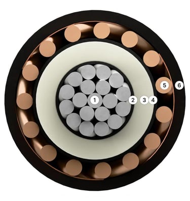
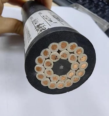
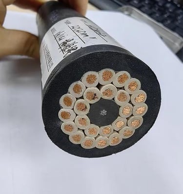
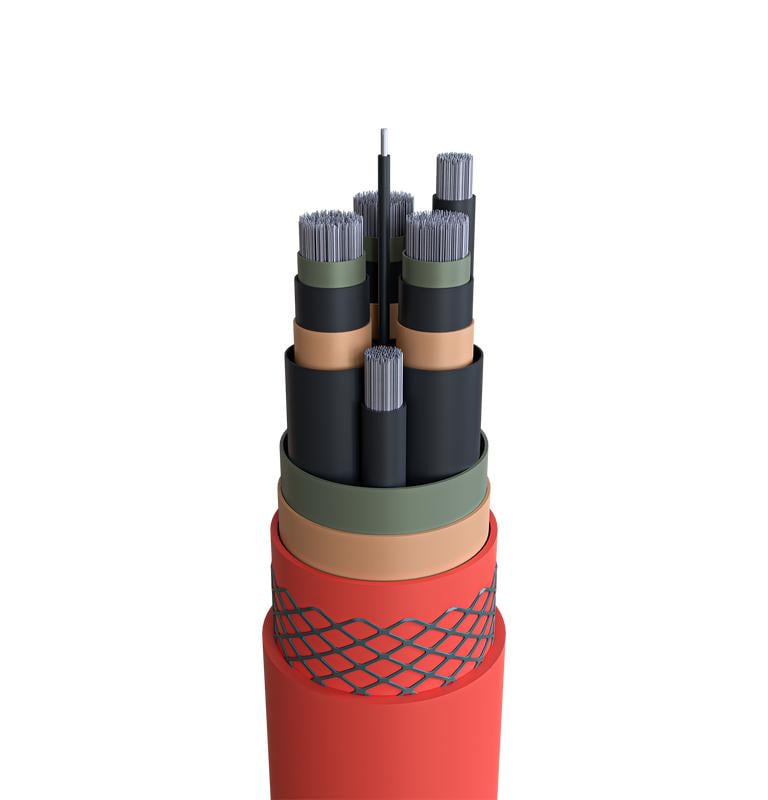
The internal architecture of a quality reeling cable reflects these priorities at every level. At the center are the conductors, typically made of annealed, very finely stranded tinned or bare copper of a high flexibility class. The fine stranding is essential because it allows the conductor to bend repeatedly without the individual wires work-hardening and snapping. Around each conductor sits a system of semi-conductive layers that control the electrical field, ensuring that the high voltage stress is distributed smoothly rather than concentrating at points where it could cause breakdown. The insulation itself is usually a special rubber compound, frequently based on ethylene propylene rubber chemistry, chosen for its excellent combination of dielectric strength, heat resistance, and mechanical flexibility.
Surrounding the insulated cores is the earth conductor, which provides the safety grounding path and is itself made of flexible stranded copper. The whole assembly is then protected by a sheath system that may include an inner sheath acting partly as a water barrier, a reinforcing anti-torsion braid made of synthetic threads such as polyester or polyamide, and a tough outer sheath built to resist abrasion, tearing, oil, ultraviolet light, and ozone. In the most advanced designs, this sheath system uses a layered "sandwich" structure where the reinforcing braid is bonded between sheath layers, producing a cable that combines flexibility with remarkable strength.
In the context of ports and mining, two voltage ratings dominate the conversation. The 6/10 kilovolt rating, meaning a cable rated for 6 kilovolts between conductor and earth and 10 kilovolts between conductors, is extremely common for medium-sized cranes and material handling equipment. The 8.7/15 kilovolt rating serves larger and more powerful machines where the higher voltage allows greater power to be delivered with manageable cable dimensions. These two ratings represent the practical heart of the medium voltage reeling cable market, and most port and mining specifications will land on one or the other depending on the power requirements of the equipment being supplied.
It is worth pausing on the temperature characteristics as well, because they shape where and how these cables can be used. A typical reeling cable allows a maximum conductor operating temperature in the region of ninety degrees Celsius during normal operation, with the ability to withstand a much higher temperature, around two hundred and fifty degrees Celsius, for the brief duration of a short circuit. At the cold end, quality cables remain serviceable at very low ambient temperatures, with fixed installation ratings reaching well below minus forty degrees Celsius and mobile operation ratings somewhat less extreme but still capable of handling harsh winter conditions. While the Gulf region rarely tests the cold limits, the high-temperature performance is directly relevant in hot climates where ambient conditions already push cables toward their thermal ceiling before any electrical load is even applied.
3. Typical Applications: Where These Cables Earn Their Keep
To understand why reeling cable must be built the way it is, it helps to look closely at the machines it serves. Each of these machines presents its own particular combination of movement, distance, and power demand, and each places its own signature of stress on the cable.
Ship-to-shore cranes, often abbreviated as STS cranes, are the giants of the container terminal. These are the enormous structures that reach out over the deck of a docked vessel, lifting containers from the ship and depositing them on the quay, or doing the reverse to load an outbound vessel. They travel along the length of the quay on rails, and as they move, a reeling cable feeds them power. The combination of high power demand, long travel distances along the berth, and the constant start-stop motion of crane operations makes the reeling cable on an STS crane one of the hardest-working electrical components in the entire port.
Rubber-tyred gantry cranes, or RTG cranes, work in the container stacking yard rather than at the quayside. Mounted on rubber tyres rather than rails, they move between rows of stacked containers, lifting and repositioning them. Because they are not confined to a fixed rail path, RTGs have particular flexibility requirements, and the reeling cable that powers the electrically driven versions must accommodate their movement patterns across the yard.
Rail-mounted gantry cranes, or RMG cranes, perform a similar stacking function but run on fixed rails, often serving rail-to-road transfer yards or intermodal facilities. Their movement is more predictable than that of an RTG, but the travel distances can be considerable, and the reeling cable must still endure continuous duty cycles.
Bucket wheel reclaimers belong to the world of bulk material handling. These are large machines with a rotating wheel fitted with buckets at the end of a long boom, used to scoop bulk material such as iron ore, coal, or grain from stockpiles and feed it onto conveyor systems. They travel along the length of a stockyard, and their reeling cables must cope with very long travel distances combined with the dust, abrasion, and harsh outdoor exposure that characterize a bulk terminal.
Ship unloaders are the machines that remove bulk cargo from a vessel's hold and transfer it ashore, whether by grab, by continuous bucket elevator, or by pneumatic conveying. Like ship-to-shore cranes, they travel along the berth and demand a reeling cable capable of handling both the power and the motion involved in continuous unloading operations.
Stacker reclaimers combine two functions in one machine: building stockpiles by stacking incoming material, and recovering material from those stockpiles to feed onward transport. They are among the largest mobile machines on any bulk handling site, traveling along rails the length of the stockyard, and their reeling cables face some of the longest travel distances in the entire industry.
What unites all of these machines is a single demanding characteristic: they require continuous or frequent movement over long travel distances while consuming large amounts of electrical power. A stationary machine can be fed by a fixed cable. A machine that moves a short distance occasionally can sometimes be managed with simpler arrangements. But a machine that travels hundreds of meters, dozens or hundreds of times per shift, while drawing the power needed to lift containers or move thousands of tonnes of bulk material, demands a cable that is engineered specifically for that combination of motion and power.
This is also where the choice of medium voltage rather than low voltage becomes important. When a large machine demands a great deal of power, that power can be delivered either as a high current at low voltage or as a lower current at medium voltage. The physics strongly favors the second approach for heavy mobile equipment. By supplying the machine at medium voltage, the current required to deliver a given amount of power is reduced, because power is the product of voltage and current. A lower current brings several practical benefits at once.
First, it reduces voltage drop along the length of the cable. Over the long travel distances typical of port and mining machinery, a low voltage supply would suffer significant voltage drop, meaning the machine at the far end of its travel would receive noticeably less voltage than intended, impairing its performance. Medium voltage supply keeps this drop within acceptable limits even over long runs. Second, lower current allows a smaller conductor cross-section for the same power, which means a lighter, more flexible, and more manageable cable, exactly what a reeling application needs. Third, lower current reduces resistive heating losses in the cable, improving overall energy efficiency and reducing the thermal stress on the cable itself.
For all of these reasons, medium voltage supply is especially well suited to high-power mobile equipment in ports and mines. The cost and complexity of medium voltage equipment is justified many times over by the efficiency, the reduced voltage drop, and the more practical cable dimensions that result. It is no accident that the largest and most power-hungry machines in any port or mine are almost universally supplied at medium voltage through reeling cables of the type described in this guide.
4. Reel System Types: How the Cable Is Stored and Deployed
A reeling cable does not exist in isolation. It works as part of a system, and the heart of that system is the reel itself, the mechanism that stores the cable and pays it out or draws it back as the machine moves. The type of reel chosen for a given application has a direct influence on the demands placed on the cable, and understanding the main reel types is essential to making a sound selection. The way the reel handles the cable determines how the cable is bent, how it is tensioned, and how evenly it is wound, all of which affect the cable's service life.
Motorized reels are the workhorses of demanding applications. As the name suggests, a motorized reel is driven by its own motor, which actively controls the winding and unwinding of the cable in coordination with the movement of the machine. This active control allows the reel to maintain proper tension on the cable across long travel distances and at high speeds, paying the cable out smoothly as the machine moves away and drawing it back in cleanly as the machine returns. Because the motor can manage tension precisely, motorized reels are suited to long travel distances, high travel speeds, and heavy-duty continuous operation. This makes them the standard choice for the large cranes and material handling machines that dominate port and mining applications. When you are dealing with a ship-to-shore crane traveling along a long berth, or a stacker reclaimer running the length of a vast stockyard, a motorized reel is almost always the appropriate solution.
Spring reels take a fundamentally different approach. Instead of a motor, they use the stored energy of a spring to take up the cable. As the machine moves away from the reel, it pulls the cable out against the spring's resistance; as the machine returns, the spring's tension draws the cable back in. This is a simple, robust, and cost-effective arrangement, but it has clear limitations. The spring's force is fixed by its design and cannot be actively controlled, which means the tension on the cable varies depending on how much cable is paid out. Spring reels are therefore best suited to shorter travel distances and to auxiliary circuits rather than main power supply. For the heavy power demands of a large crane or reclaimer, a spring reel is generally not ideal, because it cannot reliably manage the tension and length involved in such applications. Its proper place is in lighter-duty roles where simplicity and economy matter more than the ability to handle long distances and high speeds.
Monospiral reels describe an arrangement in which the cable is wound in a single spiral path, layer building upon layer in an orderly progression. This single-spiral winding is well suited to applications where the winding conditions are controlled and regular, meaning the cable is paid out and drawn back in a consistent and predictable manner. The orderly winding helps maintain the cable in good condition, but it depends on the operating conditions remaining within the range for which the reel was designed. Cables intended for monospiral and cylindrical reel applications are often subjected to particularly high mechanical stress, including very high reeling speeds and significant torsional stress, which is why cables designed for this duty place special emphasis on torsional resistance and reduced dimensions that allow them to wind neatly.
Level wind reels address a specific challenge that arises with longer cables and larger reels: the tendency of the cable to pile up unevenly on the drum. A level wind mechanism actively guides the cable back and forth across the width of the drum as it winds, laying it down in neat, even layers rather than allowing it to stack up in one area. This even winding is more than a matter of tidiness. When a cable stacks unevenly, certain sections bear excessive pressure from the layers above, and the cable can be crushed, abraded, or subjected to uneven stress that shortens its life. By guiding the cable into orderly layers, a level wind reel prevents this stacking and distributes pressure evenly across the cable. For this reason, level wind reels are particularly recommended for larger cables and for applications where long service life is a priority. The additional mechanical complexity of the level wind mechanism is repaid in the extended life and reliability of the cable it protects.
Choosing the right reel type is inseparable from choosing the right cable. A cable optimized for high torsional stress on a monospiral reel may be over-specified, and therefore unnecessarily expensive, for a simple short-travel spring reel application. Conversely, a cable that performs well on a level wind reel under controlled conditions may struggle if subjected to the more severe torsional demands of a fast monospiral system. The reel and the cable must be considered together, as two halves of a single engineered solution.
5. Key Selection Parameters: The Questions That Determine the Answer
When the time comes to specify a medium voltage reeling cable, a number of parameters must be considered together. No single parameter determines the choice; rather, they interact, and a complete specification requires attention to all of them. Let us examine each in turn, understanding not just what it is but why it matters.
The operating voltage is the natural starting point. The voltage rating of the cable must match the design of the electrical system it will serve. A cable rated at 6/10 kilovolts is appropriate for a system operating at that level, while a more powerful system designed around 8.7/15 kilovolts requires a cable rated accordingly. Selecting a cable with too low a voltage rating is dangerous, because the insulation will be subjected to electrical stress beyond what it was designed to withstand, leading eventually to breakdown. Selecting a cable rated far above the system voltage is wasteful, adding unnecessary insulation thickness, weight, and cost. The voltage rating must match the system design precisely.
The current capacity, sometimes called the current carrying capacity or ampacity, determines how much current the cable can carry continuously without overheating. This parameter directly drives the conductor size: a higher current demand requires a larger conductor cross-section to carry the load while keeping the conductor temperature within safe limits. Current capacity affects both the conductor size and the thermal performance of the cable, and it must be assessed in light of the actual electrical load of the equipment, the installation conditions, and the ambient temperature. In the hot climates common across much of the region, ambient temperature is a particularly important factor, because a cable that would carry a given current comfortably in a temperate climate may need to be derated, meaning its safe current is reduced, when operating in high ambient heat. Choosing a conductor that is too small risks overheating, accelerated insulation aging, and eventual failure.
The bending radius is one of the most critical mechanical parameters, and it is frequently underestimated. Every cable has a minimum bending radius below which it should not be bent, expressed as a multiple of the cable's outer diameter. Bending a cable more tightly than this minimum imposes excessive strain on the conductors and insulation, dramatically shortening the cable's life. For reeling cables, the minimum bending radius varies depending on the situation: a cable bent for fixed installation can tolerate a tighter radius than one being wound onto a drum or running over a deflection pulley, where the dynamic stresses are greater. A typical reeling cable might allow a minimum bending radius of around six times the outer diameter for fixed installation, but require twelve times the outer diameter when wound on a drum, fifteen times when running over deflection pulleys, and around ten times when moving freely. These differences matter enormously in practice, because the drum diameter and pulley sizing of the reel system must be designed to respect the cable's bending limits. A drum that is too small for the chosen cable will bend the cable too tightly and destroy it prematurely, no matter how well the cable is otherwise specified.
The drum diameter follows directly from the bending radius consideration. The diameter of the reel drum onto which the cable is wound must be large enough that the cable, when wound around it, is never bent more tightly than its minimum permitted radius for drum operation. Because the bending radius requirement is expressed as a multiple of the cable's outer diameter, a thicker cable requires a correspondingly larger drum. This creates an interdependence between cable size and reel design that must be resolved during the engineering of the system. Both the bending radius and the drum diameter are critical for the mechanical life of the cable, and neglecting either is a common cause of premature failure.
The travel distance is the length over which the machine moves, and it has obvious implications for the cable. The longer the travel, the more cable is required, the larger the reel must be to store it, and the greater the cumulative mechanical stress the cable will experience over its life. Long travel distances also increase the importance of voltage drop considerations, reinforcing the case for medium voltage supply discussed earlier. Travel distance influences the cable length, the tension, and the reel design all at once, and it must be known accurately at the design stage.
The reeling speed is the speed at which the cable is wound and unwound as the machine moves. Higher reeling speeds impose greater dynamic stress on the cable, because the cable must accelerate, decelerate, bend, and twist more rapidly. Quality reeling cables are rated for travel speeds that may extend to well over a hundred meters per minute, and in some demanding applications considerably higher, but the cable selected must be capable of the speed the application demands. Travel distance and reeling speed together affect the cable length, the tension experienced, and the design of the reel, and they must be considered as a pair.
The tensile load is the pulling force exerted on the cable as it is drawn along by the moving machine and the reel. A reeling cable must withstand both the steady tensile load of normal operation and the higher dynamic tensile loads that occur during acceleration, when the machine and reel are speeding up and the inertia of the cable adds to the force. Cables are rated for a maximum permissible tensile load and, separately, for a maximum dynamic tensile load during acceleration, which is typically higher. The tensile capability of the cable is closely related to its conductor cross-section and construction, and it must be matched to the forces the application will generate. A cable subjected to tensile loads beyond its rating will suffer conductor stretching, internal damage, and eventual failure.
The torsion requirement addresses the twisting forces that arise during reeling. As a cable is wound onto and off a drum, particularly with certain reel types, it is subjected to torsional stress, meaning it is twisted about its own axis. Repeated twisting is one of the most demanding stresses a cable can experience, because it works the internal structure in a way that ordinary bending does not. Quality reeling cables specify a permissible torsional stress, often expressed in degrees of twist per meter of cable length, and incorporate anti-torsion braids and carefully designed core arrangements to resist this stress. The torsion requirement of the application, which depends heavily on the reel type and the geometry of the installation, must fall within the cable's rated capability.
Both the tensile load and the torsion requirement are especially important for dynamic operation and fatigue resistance. These are the parameters that separate a cable that survives years of hard service from one that fails within months. A cable can have perfect electrical characteristics and still fail quickly if its mechanical specification does not match the tensile and torsional demands of the application. This is why a thorough selection process always gives these dynamic parameters the weight they deserve, rather than focusing only on voltage and current.
When all of these parameters are considered together, a coherent picture of the required cable emerges. The voltage rating fixes the insulation class. The current capacity fixes the minimum conductor size. The bending radius and drum diameter constrain the relationship between cable size and reel geometry. The travel distance and reeling speed determine the cable length and the dynamic stresses. The tensile load and torsion requirement set the mechanical robustness needed. Only a cable that satisfies all of these simultaneously is genuinely fit for its purpose.
6. Common Standards: The Framework of Trust
In an industry where failure carries serious consequences, standards provide the common language and the agreed benchmarks that allow engineers, manufacturers, and purchasers to trust one another's work. A cable that conforms to recognized standards has been designed, manufactured, and tested against criteria that the whole industry accepts. Understanding the principal standards relevant to medium voltage reeling cable helps you read specifications critically and ensure that what you are buying meets genuine, verifiable requirements.
The German standard DIN VDE 0250, particularly its section dealing with reeling and trailing cables, is one of the most important references in this field. It is widely used as the design basis for flexible cables intended for moving equipment, and a great many reeling cables on the market are built to conform to it. When a cable specification states that it is based on this standard, it is signaling that the cable has been designed for the dynamic mechanical demands of reeling and trailing applications, rather than for static installation. For applications involving moving equipment, conformity to this standard is a strong and meaningful indicator of suitability.
The international standard IEC 60502 is the key reference for medium voltage power cables more broadly. It covers the electrical and construction requirements for power cables in the medium voltage range, including the very ratings most relevant to port and mining applications such as 6 kilovolts, 10 kilovolts, and 15 kilovolts. Where the German reeling standard speaks to the mechanical demands of movement, this international standard speaks to the fundamental requirements of a medium voltage power cable as an electrical component. Together they frame the two essential dimensions of a reeling cable: that it is a proper medium voltage cable, and that it is built to move.
The IEC 60332 family of standards concerns the behavior of cables in fire, specifically their resistance to flame propagation. These standards define test methods for assessing whether a cable will spread flame along its length when exposed to fire, an important safety consideration in any installation where a cable fire could endanger people or property. A cable that passes the relevant flame propagation test offers an additional measure of safety, and this is particularly valuable in enclosed environments, underground mining galleries, and busy port facilities where fire safety is a serious concern. When describing the flame-resistant performance of a sheath, reference to this standard provides a recognized benchmark.
Beyond these, additional standards address specific performance aspects such as oil resistance, ultraviolet resistance, and ozone resistance, each tested against its own recognized method. For cables used outdoors in harsh industrial environments, resistance to ultraviolet light and ozone is essential to prevent the sheath from degrading under sun and weather, while oil resistance matters in environments where the cable may contact lubricants and hydraulic fluids. A well-specified reeling cable will typically carry conformity to a suite of such standards, each addressing a particular environmental or safety requirement.
For projects in Australia and New Zealand, the AS/NZS family of requirements is a relevant compliance reference, and projects in those jurisdictions will often specify conformity to them. More generally, the lesson for any project is that project-specific requirements should be checked carefully. Standards provide the foundation, but individual projects, particularly large infrastructure projects of the kind common across the region, frequently impose their own additional requirements on top of the baseline standards. A diligent procurement process establishes exactly which standards and which project-specific requirements apply, and then verifies that the proposed cable meets every one of them. Accepting a cable that meets general standards but falls short of a specific project requirement is a recipe for disputes and, worse, for installations that do not perform as the project demands.
7. Common Failure Modes: Learning From What Goes Wrong
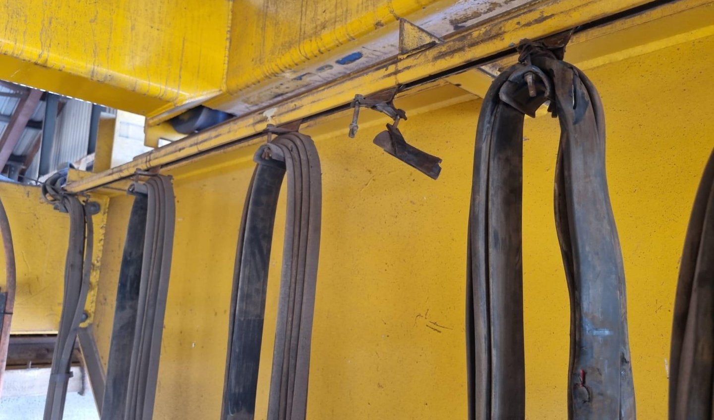
Perhaps the most useful way to understand what makes a good reeling cable is to study how cables fail. Each failure mode reveals a specific weakness, and understanding these modes helps both in selecting a robust cable and in operating it well. Failures rarely come without warning; more often they are the end point of a process of gradual degradation that could have been anticipated and prevented. Let us examine the principal ways in which a reeling cable can fail.
Core breakage is the failure of the conductor itself, the breaking of the copper that carries the current. It is caused primarily by repeated bending, by excessive tension that stretches the conductor beyond its limits, or by poor mechanical design that subjects the cable to stresses it was not built to handle. When the fine copper strands of a flexible conductor are bent back and forth too many times, or bent too tightly, or pulled too hard, they eventually fatigue and break. The consequence of core breakage is electrical instability and, ultimately, interruption of service as the current path is broken. This failure mode is precisely why reeling cables use very finely stranded conductors and why respecting the bending radius and tensile limits is so important. A cable forced beyond these limits will suffer core breakage no matter how well it is made.
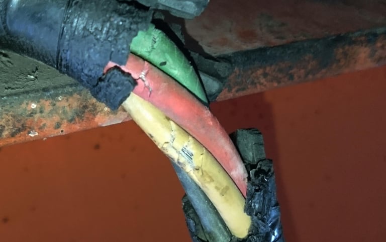
Jacket cracking, the failure of the outer sheath, is a different but equally serious problem. The sheath is the cable's armor against the outside world, and when it cracks, that protection is lost. Sheath cracking is caused by abrasion as the cable rubs against surfaces, by the natural aging of the sheath material over time, by exposure to ultraviolet light that degrades the polymer, and by brittleness that develops at low temperatures. Once the sheath cracks, moisture and dirt can penetrate into the cable's interior, attacking the insulation and the conductors and setting in motion a cascade of further problems. This is why sheath materials are chosen for their resistance to abrasion, aging, ultraviolet light, and temperature extremes, and why a quality outer sheath is one of the most important features of a reeling cable. A cracked jacket is often the beginning of the end for a cable, even if the failure that finally stops operation occurs elsewhere.
Torsion damage arises specifically from the twisting that reeling cables endure. As discussed earlier, the winding and unwinding of a cable on certain reel types subjects it to repeated torsional stress, twisting it about its own axis again and again. Over time, this repeated twisting can damage the internal structure of the cable, disturbing the careful arrangement of cores, screens, and sheaths, and shortening the cable's life. Torsion damage is insidious because it works inside the cable where it cannot be seen, and a cable may appear sound on the outside while its internal structure is being progressively compromised. The defense against torsion damage is the anti-torsion braid and the careful core arrangement built into quality reeling cables, together with selecting a cable whose torsional rating matches the demands of the application. A cable subjected to torsion beyond its rating will suffer this damage regardless of its other qualities.
Insulation failure is the failure of the dielectric that separates the conductors from one another and from earth, and it is among the most serious of all failure modes because it directly threatens electrical safety. Insulation failure can be caused by electrical overstress, when the insulation is subjected to voltage beyond what it can withstand, by mechanical damage that physically compromises the insulation, or by moisture ingress that degrades its dielectric properties. When insulation fails, the result can be an electrical breakdown, with current arcing where it should not, creating a dangerous and potentially catastrophic situation. The risk of insulation failure is why the voltage rating must always match the system, why mechanical protection of the cable is essential, and why preventing moisture ingress through an intact sheath is so important. Insulation failure is often the consequence of an earlier problem, such as a cracked jacket admitting moisture, which underlines how the various failure modes are interconnected.
Conductor fatigue is the gradual deterioration of the conductor under repeated flexing and load cycling, distinct from the sudden break of core breakage. Where core breakage is the snapping of strands, conductor fatigue is the slower process by which repeated flexing and the cycling of electrical and mechanical loads gradually degrade the conductor's properties. As fatigue accumulates, the conductor's electrical resistance can increase and its conductivity can decline, meaning the cable carries current less efficiently, runs hotter, and performs less well even before any outright break occurs. Conductor fatigue is the natural enemy of any cable that flexes for a living, and the defense against it is the use of high-quality, finely stranded, annealed copper conductors designed specifically to endure many flexing cycles, combined with operation within the cable's rated parameters.
Studying these failure modes together reveals an important truth: most reeling cable failures are mechanical in origin, even when the final symptom is electrical. The cable fails because it is bent too tightly, pulled too hard, twisted too much, or abraded until its protection is lost, and only then does the electrical failure follow. This is why the mechanical specification of a reeling cable deserves at least as much attention as its electrical rating, and why understanding the demands of the application, in terms of bending, tension, torsion, and abrasion, is the foundation of a successful selection. A cable chosen to withstand the mechanical reality of its application will, in the great majority of cases, also deliver the electrical reliability the operation depends upon.
8. Recommended Product Series: Matching the Cable to the Application
With the principles established, we can now consider the families of cable that are designed for these applications. Several product series are well suited to medium voltage reeling duty in ports and mining, and understanding how they are positioned helps in matching a cable to a specific need.
A core family of reeling cable, identified by the type designation NTSCGEWOEU, is designed precisely for the dynamic medium voltage applications discussed throughout this guide. Cables of the NTSCGEWOEU type are built for flexible medium voltage reeling duty under high to extreme mechanical stresses, including high travel speeds, dynamic tensile loads, frequent changes of direction across different planes, the churning that occurs as the cable runs over rollers, and significant torsional stresses. They are designed primarily for mobile equipment such as fast-moving container cranes and large moving machines, which places them squarely in the heart of port and mining applications.
A closely related variant, designated R-(N)TSCGEWOEU, is specially designed as a flexible reeling cable with reduced dimensions to handle the extremely high mechanical stresses that occur in applications using monospiral reels and cylindrical reels, where very high reeling speeds and torsional stress are the rule. The reduced dimensions are not a cost-cutting measure but a deliberate engineering choice, because a more compact cable winds more neatly onto a spiral reel and handles the associated stresses better. This variant is also well suited to connecting large material handling machines such as excavators, dumpers, and crushers in open-cast mines, and is built for use in wet or dry conditions, in industrial units, in underground and open-cast mining, and even in explosion-risk areas where appropriately certified. Some versions of this cable also integrate fiber optic modules within the cable structure, allowing data and control signals to travel alongside the power cores, an increasingly valuable feature as ports and mines become more automated and require communication links to their mobile equipment.
These cables are offered across the full range of relevant voltage ratings. The 6/10 kilovolt reeling cable serves the large population of medium-sized cranes and material handling equipment that operate at this level, offering an excellent balance of power capability and manageable dimensions. The 8.7/15 kilovolt reeling cable serves the more powerful machines where the higher voltage allows greater power delivery, and is commonly specified for the largest cranes and reclaimers. Lower ratings such as 3.6/6 kilovolts and even 1.8/3 kilovolts serve smaller or lower-voltage applications, while higher ratings extending to 12/20 kilovolts and beyond serve the most demanding installations. This breadth of voltage options means that whatever the system design, a suitably rated cable from the same well-proven family is available.
These product series, the NTSCGEWOEU and the reduced-dimension R-(N)TSCGEWOEU, should be understood as suitable examples of what a quality medium voltage reeling cable looks like, and as a starting point for specification rather than an automatic answer. They can be positioned confidently for ports, for mining, and for heavy-duty crane systems of all kinds. But the essential point, which cannot be repeated too often, is that the final selection must match the specific voltage, the specific mechanical stresses, and the specific reel system type of the actual application. A cable family may offer a member suited to almost any application, but choosing the right member of that family, with the right voltage rating, the right conductor size, and the right mechanical specification, is the work that determines success or failure. The product series provides the raw material; the engineering judgment provides the solution.
In practice, this means working through the selection parameters discussed earlier, establishing the voltage rating from the system design, the conductor size from the current demand and the ambient conditions, the bending radius and drum compatibility from the reel geometry, and the tensile and torsional requirements from the dynamics of the installation, and then identifying the member of the product family that satisfies every one of these requirements. When this is done carefully, the result is a cable that disappears into reliable service, exactly as a well-chosen reeling cable should.
9. Conclusion: The Discipline of a Good Decision
We began this guide by observing that the reeling cable is a component that receives little attention until it fails, and we have spent the intervening pages explaining why it deserves a great deal more attention than that. Let us draw the threads together.
Medium voltage reeling cable is a specialized solution for a specialized problem: the delivery of high electrical power to heavy equipment that is in constant motion. It exists because the ordinary cables of fixed installation cannot survive the bending, twisting, pulling, and abrasion that reeling applications impose, and because the heavy mobile machines of ports and mines need power delivered efficiently over long, moving travel paths. From its finely stranded flexible conductors to its reinforced multi-layer sheath, every feature of a quality reeling cable is an answer to a specific demand of dynamic, high-power service.
The selection of such a cable is not a matter of picking a part number from a catalog. It is an exercise in matching a cable's capabilities to the precise demands of an application, and proper selection depends on a clear understanding of voltage, current, bending radius, travel distance, reeling speed, tensile load, and torsion. Each of these parameters constrains the choice, and only a cable that satisfies all of them simultaneously is genuinely fit for purpose. Neglecting any one of them, whether the voltage rating that protects the insulation, the bending radius that the drum must respect, or the torsional rating that the reel type demands, opens the door to one of the failure modes we have examined, and to the costly, disruptive downtime that follows.
The framework of standards exists to give all parties confidence that a cable will perform as claimed, and conformity to the relevant standards, together with careful attention to any project-specific requirements, is essential to safe and reliable operation. Equally essential is an understanding of how cables fail, because most failures are mechanical in origin and most are preventable through correct selection and correct operation. The cable that is chosen to match the mechanical reality of its application, and then operated within its rated limits, will reward that care with years of dependable service.
For the ports and mines of the region, where the scale of operations is large, the climate is demanding, and the cost of downtime is high, this care is not a luxury but a necessity. Product series such as the NTSCGEWOEU and R-(N)TSCGEWOEU, available across the full range of relevant voltage ratings from 1.8/3 kV through 6/10 kV and 8.7/15 kV to 12/20 kV and beyond, and engineered for the harshest reeling conditions, provide suitable and proven solutions for port and mining applications. But they provide those solutions only in the hands of those who select them with discipline and understanding. The cable is the tool; the engineering judgment is what makes it work.
If there is a single message to carry away from this guide, it is this: treat the reeling cable not as an afterthought but as the critical component it is, give its selection the same rigor you would give to the machine it serves, and you will be rewarded with the quiet, invisible reliability that is the mark of a decision made well. In an operation where every hour of uptime matters, the cable that never fails is worth far more than its modest share of the project cost. Choosing that cable, with knowledge and with care, is the purpose this guide has tried to serve.
Port crane cables | Mining cables | Reeling cables | Trailing cables | Festoon cables | Heavy-duty power cables | Medium voltage cables | Offshore crane cables | Underground mining cables | Dragline cables | Shearer cables | Container handling cables | STS crane cables | RTG cables | Mobile equipment cables | Armored cables | Flexible power cables | VFD cables | Submersible cables | Cold resistant cables | Abrasion resistant cables | Flame retardant cables | Marine environment cables | Opencast mining | Underground operations
© 2006 All rights reserved.
[INDUSTRIAL_CABLES]
INDUSTRIAL GRADE CABLE SYSTEMS | PORT & MINING SOLUTIONS
TEL: +86 153 7530 2641 |MAIL: hongjing.Wang@feichuncables.com