
(N)GFLCGOEU-J Screened Flat Crane Cable: Application Engineering for Port and Terminal Equipment
DIN VDE 0250-809 | EPR Insulated | 0.6/1 kV | EMC Protected | Marine Environment Rated
CRANE CABLE
hongjing.Wang@Feichun
3/5/202622 min read
Introduction: The Cable Challenge in Modern Port Automation
Container ports and bulk terminals are among the most mechanically demanding environments for electrical cables. Ship-to-shore (STS) quay cranes cycling thousands of times per day, rubber-tyred gantry (RTG) cranes traversing hundreds of metres per shift, and automated stacking cranes operating 24/7 impose cumulative fatigue cycles that standard industrial cables are not engineered to withstand.
At the same time, modern port equipment relies heavily on variable frequency drives (VFDs), encoder feedback loops, and PLC-based motion controllers. Electromagnetic interference (EMI) generated by these drives can corrupt position signals, trigger nuisance faults, and cause dangerous uncommanded crane motions. An unscreened flat cable running in a festoon system on a spreader trolley is therefore simultaneously a mechanical liability and an EMC risk.
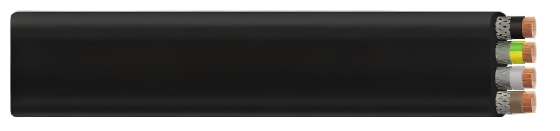
The (N)GFLCGOEU-J screened flat rubber cable, manufactured to DIN VDE 0250-809, addresses both challenges within a single product. Its EPR insulation and heavy-duty rubber sheath deliver the flexibility and chemical resistance required in open-air port environments, while its tinned copper braid screen with 85% coverage provides effective EMC shielding for sensitive drive and control circuits.
This guide examines the technical requirements of the principal port crane types, the mechanical stress modes encountered in festoon and cable reel installations, failure risk profiles, and the engineering solutions that a well-specified screened flat rubber cable provides.
Product Overview and Design Rationale
The (N)GFLCGOEU-J is classified as a screened, flexible, low-voltage flat rubber cable. Its designation encodes its principal design intent:
N — Not propagating flame; fire-retardant construction per EN 60332-1-2
G — Rubber outer sheath; specifically heavy-duty compound type 5GM3
FL — Flat geometry; designed for festoon and linear-travel applications
C — Copper conductors
G — Rubber insulation; EPR compound type 3GI3
OE — Oil-resistant outer sheath; compliance per EN 60811-404
U — Universal; suitable for both fixed and flexible duty cycles
J — Screened version with tinned copper wire braid
The cable is rated at 0.6/1 kV and may be applied in AC systems up to 0.7/1.2 kV and in DC systems up to 0.9/1.8 kV. With a maximum conductor operating temperature of 90 °C and a short-circuit rating of 250 °C, it is thermally well-suited to the high-current demands of traction and hoist drives common in port cranes.
Key parameters at a glance:
Rated voltage (U₀/U): 0.6/1 kV. Maximum permissible operating voltage in AC systems: 0.7/1.2 kV. Maximum permissible operating voltage in DC systems: 0.9/1.8 kV. AC test voltage: 3.5 kV for 5 minutes. Maximum conductor temperature (continuous): 90 °C. Short-circuit conductor temperature: 250 °C. Ambient temperature for fixed installation: −40 °C to +80 °C. Ambient temperature for festoon operation: −30 °C to +80 °C. Maximum tensile load on conductor: 15 N/mm². Maximum trolley travel speed: 180 m/min. Current-carrying capacities: per DIN VDE 0298-4.
Current-carrying capacities must be derated for the specific installation method. Festoon-installed cables typically require a derating factor of 0.8 to 0.9 compared to free-air values, depending on the number of cables per hanger bracket and the ambient temperature at the installation site.
Port Crane Application Scenarios
STS Quay Cranes (Ship-to-Shore)
STS cranes represent the highest cable-stress application in a container terminal. A typical Post-Panamax or Ultra-Large Container Vessel quay crane has the following cable runs where screened flat festoon cable is the product of choice.
Trolley festoon system: The spreader trolley travels the full outreach — typically 60 to 70 m — at speeds up to 180 m/min, completing thousands of return cycles per day. The festoon cable must sustain high-frequency bending in one plane with minimal sag variation throughout each shift. This is the most demanding application of the cable's fatigue properties and the primary design case for cross-section and bending radius selection.
Boom hinge power supply: Cables bridging the boom hinge experience compound bending as the boom is raised and lowered for vessel arrival and departure. This is an extreme use case requiring the cable to be routed with adequate slack and guided in a fixed festoon loop with carefully controlled entry and exit radii at the hinge point.
Operator cabin supply: Vertical cab-travel cables on elevated cranes may be routed through a C-track with controlled bending radius. The flat geometry provides compact cable management within the confined crane leg structure, and the individual screens are particularly valuable for protecting cabin communication and safety system wiring from VFD emissions in the adjacent machinery house.
Engineering note — tensile load on STS festoon: The maximum tensile load of 15 N/mm² per conductor is the governing design criterion. For 4×16 mm² conductors, this equates to a maximum allowable force of approximately 960 N. Verify against the actual festoon dead load, sag geometry, and dynamic acceleration factor — typically 1.3 to 1.8 — for each specific installation.
Rubber-Tyred Gantry Cranes (RTG)
RTG cranes are self-propelled, diesel-electric or grid-electric gantry cranes that straddle container rows in the yard. Cable requirements arise primarily from the trolley travel festoon and inter-axle circuits.
Trolley travel festoon: The spreader trolley rides a festoon cable across the gantry width — typically 23 m on an 8-wide crane. Cycle counts are lower than STS operations but remain very high in busy terminals, and in automated RTG systems with no operator rest periods the cable accumulates fatigue cycles continuously.
Cable reel sub-circuits: Grid-connected RTGs receive main power via a spring-tension or motorised cable reel. Flat cable is not appropriate for the reel drum itself — round cable is better suited to multi-layer winding — but where reel-fed festoon sub-circuits supply the trolley or spreader within the crane structure, the flat cable format is standard and provides compact cable management within the structural members.
Inter-axle power and signal cables: In electrically-interconnected bogies, flexible cables must accommodate relative motion during cornering and travel over uneven yard surfaces. Short, well-guided sections of flat cable with adequate slack loops are the standard solution.
Rail-Mounted Gantry Cranes (RMG) and Automated Stacking Cranes (ASC)
RMG and ASC installations in automated terminals operate with extreme cycle regularity and are designed for service lives exceeding 20 years with minimal maintenance intervention. The individually screened cores of the (N)GFLCGOEU-J are particularly valuable in these applications.
ASC motion controllers use high-resolution resolvers and encoder signals operating at 100 kHz to 1 MHz clock frequencies — frequencies that are highly susceptible to common-mode noise from VFD switching transients. Long cable runs, up to 600 m on deep-water container berths, increase the risk of capacitive coupling between power and signal circuits without adequate screening. Because automated systems operate without continuous human oversight, an EMC-induced fault has a significantly higher probability of going undetected until a plant-wide stoppage occurs.
The 85% coverage tinned copper braid provides effective shielding transfer impedance below 100 mΩ/m at drive-switching frequencies, meeting the IEC 61000-4-6 conducted immunity requirements applicable to automation controllers installed in this environment.
Ship Loaders and Continuous Ship Unloaders
Ship loaders convey bulk material — grain, coal, iron ore — from conveyor systems to vessel holds. The loading boom is raised and slewed, creating a cable management challenge at the boom pivot where the cable must accommodate multi-axis angular displacement.
Boom cable festoon: The outboard conveyor drive and belt-monitoring cables run in a festoon along the boom structure, bending only in the vertical plane during luffing. This is a benign, one-plane bending application well within the cable's design envelope and the most straightforward application on a ship loader.
Slew ring cable crossing: A short section of flat cable bridges the slew ring, guided in an external C-track that constrains bending to one axis. This is a demanding position: the cable must sustain both cyclic bending and a degree of longitudinal displacement as the slew angle changes. Full fatigue characterisation of the routing geometry is required before finalising the installation design.
Tripper car cables: On long conveyors, a travelling tripper car distributes material along a stockpile. Festoon cables supply the tripper drive and dust-suppression system over travel distances of up to 300 m in large coal and ore terminals, making this application directly comparable to RMG long-travel circuits in terms of festoon design requirements.
Stackers and Reclaimers
Portal scrapers, bridge reclaimers, and bucket-wheel reclaimers operate on long rail tracks at ore and coal terminals. Cable requirements are similar to RMG systems but with greater travel distances — up to 1,000 m — and more aggressive environmental conditions including fugitive dust, persistent moisture, and wide temperature variation between seasons.
Long-travel festoon: With travel distances exceeding 200 m, festoon systems for stackers and reclaimers are among the most mechanically complex in any industrial application. Cable sag must be precisely controlled to prevent inter-cable contact, and the bending radius at each festoon hanger bracket must comply with the 4×H or 5×H requirements throughout the full travel stroke including at the endpoints where sag is minimum and cable tension is maximum.
Luffing boom cables: The counterweighted luffing mechanism creates high dynamic forces on cable routing near the boom pivot. A case-by-case load analysis — including calculation of the dynamic tensile force at maximum luffing speed and acceleration — is mandatory before specifying cable cross-section and routing for this position.
Slewing cables on bucket-wheel reclaimers: Cables supplying the bucket-wheel motor must traverse the full slew arc, typically ±200° or more. This application is managed by a dedicated motorised cable reel with tension control rather than a festoon. The flat cable is not appropriate for the slewing reel drum itself but may be used for secondary circuits within the fixed structure downstream of the slew ring.
Mechanical Stress Analysis
Bending Stress and Fatigue Life
The dominant failure mechanism for festoon cables is bending fatigue — the cyclic stress induced as the cable passes around a festoon hanger bracket or over a guide roller. The flat geometry of the (N)GFLCGOEU-J constrains bending to a single plane, which is both a design advantage (predictable, calculable stress field) and a design requirement (multi-plane bending will initiate premature fatigue at twisted conductor cross-sections and is not permitted by the cable standard).
The minimum bending radius is specified as a multiple of the cable height H — the smaller of the two cross-sectional dimensions of the flat cable body. For cable heights up to 12 mm, the minimum bending radius is 3×H for fixed installations and 4×H for flexible applications including festoon. For cable heights above 12 mm, the minimum is 4×H for fixed and 5×H for flexible applications.
As a worked example: a 4×16 mm² cable with a typical height of 13 mm requires a minimum festoon bending radius of 5×13 = 65 mm. Festoon hanger brackets must be designed such that the cable does not contact the bracket edge at a radius smaller than this value under any combination of sag geometry and trolley position — including at the endpoints of travel where sag is at minimum and cable tension is at maximum.
Tensile Stress
Tensile stress arises from cable dead weight in the catenary between hangers, dynamic acceleration forces as the trolley accelerates and decelerates, and wind loading on exposed festoon runs. The maximum allowable tensile load on conductors is 15 N/mm². For representative port crane cross-sections, the permissible tensile forces are as follows:
4×6 mm² conductors: maximum permissible tensile force 360 N
4×16 mm² conductors: maximum permissible tensile force 960 N
4×25 mm² conductors: maximum permissible tensile force 1,500 N
4×35 mm² conductors: maximum permissible tensile force 2,100 N
4×50 mm² conductors: maximum permissible tensile force 3,000 N
For large cross-sections of 35 mm² and above, the cable standard requires a case-by-case mechanical assessment. This must include a dynamic load factor, typically 1.3 to 1.8 depending on the trolley acceleration profile, applied to the static catenary tension calculated from sag geometry and cable weight per metre.
Warning — high-speed festoon applications: At trolley travel speeds approaching 180 m/min, dynamic oscillation of the festoon cable can generate transient tensile peaks significantly above the static catenary load. For high-speed STS or RMG trolley festoon circuits, commissioning must include direct measurement of peak cable tension under full-speed acceleration to verify that transient loads remain within the 15 N/mm² limit.
Torsional Stress
Torsion is the most frequently overlooked stress mode in festoon cable design and is responsible for a disproportionate share of premature failures in port crane installations. When festoon hangers are misaligned — due to rail-level variation, hanger bracket manufacturing tolerance, or settlement of the support structure — cables experience imposed twist at each hanger bracket. Over thousands of cycles, torsional fatigue causes conductor wire breakage at the bracket exit point, a failure that is difficult to detect by visual inspection until the cable has already failed electrically.
Three engineering measures are effective in eliminating torsional stress. First, install swivel-type festoon hangers that allow free rotation of the cable attachment point, eliminating the imposed torsion generated by rail-level variation along the full travel length. Second, maintain hanger spacing within ±5 mm of the design value along the full rail length to prevent differential sag inducing rotational forces between adjacent hangers. Third, during initial cable threading, verify that no twist has been imposed by marking the cable sheath with a chalk line along its length before threading: one full twist per hanger spacing will fatigue the cable to failure within 6 to 12 months of operation.
Compressive and Lateral Forces
In C-track guided systems — used for RTG trolley cables and elevated cabin cables — the cable is constrained laterally by the track walls. If the track inner width is not adequately matched to the cable width, the cable experiences lateral compression during bending, particularly at the entry and exit tangent points of the guide curve. The typical design clearance is +0 to +3 mm between the cable nominal width and the track inner dimension. Over time, under-dimensioned tracks crush the flat cross-section and cause premature cracking of the insulation at the inner bend. C-track inner dimensions must be verified against the actual cable width — nominal plus maximum dimensional tolerance — before track fabrication is finalised.


Installation Methods
Festoon Systems
The festoon arrangement — where cables hang in a series of catenary loops supported by travelling hangers mounted on a horizontal rail — is the standard solution for STS trolley cables, RMG trolley cables, and the long-travel main power circuits of stacker and reclaimer machines.
Hanger spacing is typically 1.5 to 2.5 m for flat cables up to 25 mm² conductors. Closer spacing increases the cycle count per hanger bracket but reduces catenary tension and torsional sensitivity. Wider spacing is acceptable for slow-speed, low-cycle applications such as stacker long-travel circuits where the dominant design constraint is catenary tension rather than fatigue life.
Sag ratio — cable sag expressed as a proportion of hanger spacing — should be maintained at 10 to 15% to minimise both tensile stress from excessive sag and bending stress concentration at the hanger bracket caused by insufficient sag. Sag ratio increases at high ambient temperatures as the rubber sheath relaxes; design for the maximum anticipated ambient temperature, not the installation-day condition.
End attachment and strain relief is critical: the cable must be fixed with a proprietary strain relief grip at both the moving end (spreader trolley or cabin) and the stationary end (conductor rail or junction box). The strain relief grip must transfer the full tensile load to the cable sheath, not to the conductors. Connecting tensile load through the conductor terminations will fracture crimp connections within weeks of commissioning on a high-cycle festoon.
For weather protection on open-air STS and stacker/reclaimer festoon rails, the heavy-duty type 5GM3 rubber sheath provides unrestricted outdoor service. No additional weatherproofing or UV-protective wrapping is required under normal port conditions in temperate or tropical climates.
Cable Reel Systems
Motorised cable reels are used for main power supply to rail-mounted cranes where travel distances make a festoon arrangement impractical. The (N)GFLCGOEU-J flat cable is not a primary choice for cable reel drum applications. Round cable is inherently better suited to multi-layer drum winding due to its rotationally symmetric cross-section. Flat cable wound on a reel also develops lateral stresses at the drum flanges during winding and unwinding that are outside the bending-in-one-plane design envelope of the cable standard.
For reel drum applications, specify a round screened flexible rubber cable with equivalent insulation and sheath construction. The flat (N)GFLCGOEU-J is appropriate for festoon sub-circuits downstream of the reel-end junction box, where the flat geometry provides cable management advantages within the confined structural members of the crane body.
Vertical Basket (Drop Cable) Arrangements
On elevated structures — STS crane operator cabins, the elevated machinery houses of bucket-wheel reclaimers, and bridge cranes with high-lift cab arrangements — cable runs between the stationary structure and the moving component may be arranged vertically, with the cable hanging in a free-fall loop. This arrangement is known as a vertical basket or drop cable installation.
Cable weight management: Flat cables have a higher mass per metre than equivalent round cables due to the parallel-core arrangement. For vertical drops exceeding 20 m, the accumulated cable weight in the loop may approach or exceed the permissible tensile load on the conductor cross-section. A detailed weight and tension calculation is mandatory for any vertical drop exceeding 15 m.
Loop radius at the base: The loop at the bottom of a vertical drop must maintain the minimum bending radius at all times, including when the moving component is at its lowest position and the loop is at maximum compaction. In practice, this constraint often sets the minimum free-fall length of the drop arrangement rather than the tensile load calculation.
Guiding elements: The cable must be guided at both the top and bottom attachment points with properly radiused clamps and strain relief fittings. Bending concentration at a sharp-edged fixing point is one of the most common causes of early failure in vertical basket installations.
Wind loading and galloping: In exposed outdoor installations, wind loading on a freely hanging flat cable can induce lateral oscillation — Aeolian galloping — that imposes torsional and bending stresses outside the one-plane bending design envelope. A guide tube or enclosed C-track is strongly recommended for vertical drops exceeding 15 m in open-air environments exposed to prevailing wind.
Technical Construction: Engineering Rationale
Conductor Selection
For conductors up to 25 mm², Class 6 extra-fine stranded wires per EN 60228 are specified, with individual wire diameters of 0.16 to 0.21 mm. This fine stranding provides the maximum resistance to fatigue fracture under repeated flexing. Each bending cycle causes micro-slip between individual wires; fine stranding distributes this slip across a larger number of wire-to-wire contacts, dramatically extending fatigue life compared to coarser Class 2 or Class 5 stranding.
For conductors 35 mm² and above, Class 5 fine stranded is specified. The increased cross-section inherently provides greater absolute flexibility, and the additional cost of Class 6 stranding at large cross-sections is not offset by a commensurate improvement in service life for the bending radii encountered in crane festoon applications.
EPR Insulation
Ethylene Propylene Rubber (EPR, compound type 3GI3 to DIN VDE 0207-20) is the optimal insulation material for dynamic cable applications in port environments. Its low modulus of elasticity — significantly lower than XLPE or PVC — reduces the restoring force generated when the insulation is bent, reducing the bending moment applied to the conductor during festoon operation and extending fatigue life. Its operating temperature range from −30 °C to +90 °C accommodates Arctic bulk terminals in winter and tropical container terminals in summer within a single product specification. Its inherent resistance to ozone, UV radiation, and moisture absorption makes it suitable for unrestricted outdoor use in marine and industrial atmospheres without additional protective coatings. Its hydrolysis resistance ensures that electrical insulation properties are maintained after prolonged water exposure — relevant in wash-down areas beneath crane machinery houses and in marine spray zones on exposed berths.
Individual Core Screening
Each core in the (N)GFLCGOEU-J is individually screened with a tinned copper wire braid providing 85% coverage. This architecture — individual screens rather than a single overall screen — offers important advantages in port crane applications. Where power cores and signal or control cores are combined in the same cable body, individual screening ensures that crosstalk between adjacent cores is minimised regardless of the frequency or amplitude of the interfering signal. An individual screen closely follows its core during bending, maintaining more consistent coverage at tight bend radii than an overall screen, which can develop localised coverage gaps on the inside of a bend. Individual screens also allow selective grounding: both ends grounded for EMI suppression on power circuits, or one end only grounded to prevent ground-loop currents in high-frequency signal circuits such as resolver and encoder feedback.
Heavy-Duty Rubber Outer Sheath
The type 5GM3 heavy-duty rubber compound sheath provides the cable's primary mechanical protection against abrasion, impact, and chemical exposure. Its oil resistance per EN 60811-404 is essential in crane machinery houses where hydraulic fluid and gear lubricant contamination of cable runs is unavoidable. Its flame-retardant behaviour per EN 60332-1-2 — the cable does not propagate flame along its length — is critical in confined cable management within crane structures where fire spread could cause catastrophic loss of the crane and adjacent equipment. The flat cross-section of the 5GM3 compound provides inherent resistance to crushing by overhead cable carrier track systems, and the compound's high tear strength resists puncture by dropped rigging hardware — a realistic hazard on active crane structures.
Environmental Performance in Marine Port Environments
The port environment presents a combination of stressors not individually encountered in typical industrial settings. The following summarises the relevant challenges and how the (N)GFLCGOEU-J construction responds to each.
Salt spray and marine atmosphere: The 5GM3 rubber sheath is inherently impermeable to chloride ions, and the tinned copper screen resists galvanic corrosion in saline-humid atmospheres better than an untreated copper braid. This is particularly relevant for open-air festoon systems on berth-side STS cranes within the tidal spray zone.
UV radiation: Both EPR insulation and the 5GM3 outer sheath have proven long-term UV resistance. No UV-stabiliser coating or supplementary protective wrapping is required in tropical or sub-tropical terminal environments.
Temperature extremes: The ambient operating range of −30 °C for festoon service to +80 °C covers the full spectrum from Arctic bulk terminals in winter to tropical container terminals in summer, including solar loading on exposed dark-coloured cable surfaces. At the lower temperature limit, EPR retains significantly more flexibility than PVC or XLPE, which is critical for cold-start festoon operation where cable stiffness must not prevent self-hanging loop formation.
Oil and hydraulic fluid: Oil resistance per EN 60811-404 is verified for the outer sheath compound. In crane machinery houses with high-pressure hydraulic systems, the probability of sheath contact with mineral oil or synthetic hydraulic fluid is high, and a cable without verified oil resistance will suffer sheath swelling and subsequent mechanical failure within months of exposure.
Mechanical impact: Flat cables offer inherent resistance to impact loading compared to round cables of equivalent conductor cross-section, as the flat geometry distributes an impact force over a larger sheath area. The 5GM3 compound's high tear strength provides additional resistance to puncture from dropped hardware.
Ozone: Both EPR insulation and the 5GM3 outer sheath are inherently ozone-resistant. No additional protection is required in environments with elevated ozone concentrations near high-voltage switchgear or drive output circuits.
EMC Engineering for Port Crane Drive Systems
Modern port cranes universally employ variable frequency drives for hoist, trolley travel, and long-travel motions. These drives generate conducted and radiated emissions with significant spectral content at PWM switching frequencies — typically 2 to 16 kHz — and their harmonics, extending into the low-megahertz range.
In a typical STS quay crane, the following EMC-sensitive circuits share cable trays or festoon systems with VFD power cables: absolute position encoders for hoist and trolley using SSI or EnDat protocols at 100 kHz to 1 MHz clock frequencies; load cell signals from spreader weighing systems at millivolt-level outputs susceptible to microvolt-scale noise injection; Profibus-DP or EtherNet/IP fieldbus cables for drive control at 9.6 Mbit/s to 100 Mbit/s; and safety PLC wiring for anti-collision, overload, and wind speed protection systems.
The individually screened cores of the (N)GFLCGOEU-J provide a practical solution for combined power and control circuits in a single cable body. However, for the most EMC-sensitive applications — particularly load cell signals and safety system wiring — a separate dedicated screened cable is strongly recommended, routed at maximum practical distance from VFD power cables and ideally in a separate metallic conduit or cable tray bonded at both ends.
Grounding topology is critical to screen performance. For power circuit screens, ground the screen at both ends to suppress emission from VFD output cables. For instrumentation and signal circuit screens, ground the screen at the control panel end only, leaving the field end floating, to prevent common-mode noise injection via ground-loop currents. Mixing both topologies in a multi-core cable requires careful circuit segregation at each junction box, clearly documented in the as-built wiring schedule.
Long festoon cable runs introduce distributed capacitance between the screen and the insulated cores, creating a significant high-frequency current path in the screen grounding circuit. For festoon runs exceeding 50 m with both-ends screen grounding, verify that the screen grounding conductor cross-section is sufficient to carry the expected screening current without developing a significant voltage drop that would compromise screen effectiveness.
Typical Failure Modes and Engineering Solutions
Conductor Fatigue Fracture
Root cause: bending radius below the minimum at hanger brackets; excessive tensile load; torsional stress from misaligned hanger rail.
Detection: insulation resistance test; milliohm-range DC resistance measurement on each conductor; partial-load thermal imaging of terminations showing asymmetric heating.
Engineering solution: verify festoon geometry against minimum bending radius for the installed cable height; install swivel-type hangers; correct rail alignment; re-tension festoon to design sag ratio of 10 to 15%.
Outer Sheath Cracking
Root cause: UV degradation of inadequate sheath compound; ozone attack at sustained high-voltage discharge points; mechanical abrasion at unguarded rail entry points.
Detection: visual inspection with illuminated magnifier; crack depth measurement — replace when cracks exceed 50% of sheath wall thickness; megger test at 1 kV DC to confirm insulation integrity.
Engineering solution: specify 5GM3 rubber sheath as required by the cable standard; install radiused anti-abrasion cable guides at all rail entry and exit points; protect cable from UV exposure if a non-standard sheath compound has been installed in a previous generation.
Screen Continuity Failure
Root cause: screen braid fracture at festoon hanger clamp due to combined bending and longitudinal tension at the clamp edge; galvanic corrosion of copper braid in marine atmosphere over extended service periods.
Detection: end-to-end screen continuity test; EMC emission scan of drive output circuit; comparison of drive fault log frequency before and after the suspected screen failure event.
Engineering solution: use tinned copper braid as specified in the cable standard, which is significantly more resistant to galvanic corrosion than untreated copper in marine atmospheres; verify hanger clamp design provides screen continuity through the grounding circuit rather than clamping the screen directly at a bending point.
Inter-Core Insulation Breakdown
Root cause: water ingress at end terminations with inadequate cable gland sealing; conductor fatigue creating intermittent contact pressure on adjacent insulation walls in heavily aged cable; chemical degradation of EPR from unidentified solvent exposure.
Detection: phase-to-phase insulation resistance measurement; partial discharge test at 3 kV; power analyser monitoring for gradual ground fault current increase over weeks or months.
Engineering solution: use IP54 minimum rated cable glands with appropriate polymer insert for the cable cross-section; inspect gland seals annually in marine environments; replace gland inserts at 5-year intervals regardless of visual condition.
Cable Snagging or Jamming in Festoon
Root cause: incorrect festoon hanger spacing leading to uncontrolled loop formation between hangers; cable sag exceeding design limit after thermal softening of the sheath compound at high ambient temperature; foreign object intrusion in the festoon channel.
Detection: visual inspection across the full travel stroke; trolley drive current monitoring — snagging events produce characteristic current spikes that are detectable in the drive event log if data logging is enabled.
Engineering solution: install sag-monitoring physical guides at mid-span positions in high-temperature zones; increase hanger density in sections exposed to elevated ambient temperature or high wind loading; install physical end-stops on the festoon channel to prevent foreign object entry from adjacent crane activities.
EMC-Induced Control Faults
Root cause: screen not grounded at the correct end for the circuit type; screen continuity interrupted at a junction box through an incorrect wiring connection; inadequate screen coverage on signal cores due to overly tight bending in the cable routing within the crane structure.
Detection: EMC spectrum scan of cable bundle with all VFD drives running at full duty; comparison against IEC 61000-4-6 immunity test levels; oscilloscope capture of noise on encoder signal lines during drive switching events.
Engineering solution: verify and correct screen grounding topology for each individual circuit type at every junction box in the system; install ferrite cores on VFD output cable ends at the drive output terminals as a secondary measure; increase separation distance between power and signal cable trays within the crane structure wherever the routing permits.
Residual Life Assessment for Existing Installations
Cycle count logging from the crane PLC — comparing accumulated trolley travel cycles against fatigue test data for the installed cable grade — provides the most objective retirement criterion and should be the primary basis for replacement planning in automated terminals. Annual insulation resistance trending using megger testing at 1 kV DC will reveal any systematic downward trend in IR values before a catastrophic breakdown event, provided the trending data is retained and reviewed. Visual sheath inspection with crack depth measurement using a calibrated illuminated magnifier should be conducted semi-annually on high-cycle festoon applications: cracks penetrating more than 50% of the sheath wall thickness indicate replacement is required regardless of current electrical test results.
Specification and Selection Guide
Cross-Section Selection by Application
The following guidance covers the most common circuit types on port cranes. All selections must be verified against actual current load, cable length, installation derating factor, and ambient temperature before finalising the specification.
STS trolley main drive power (one motor circuit): Typically 4×25 to 4×50 mm² depending on motor rating. Current rating must be determined per DIN VDE 0298-4 for the festoon installation method, with a derating factor of 0.8 to 0.9 applied for high ambient temperature in tropical terminals and for multi-cable festoon carriers.
RTG and RMG trolley auxiliary power: Typically 4×6 to 4×16 mm². Include a 20% current derating margin in terminals with consistently high ambient temperatures — an allowance that is easily overlooked when designing to standard European ambient temperature assumptions.
Combined control and signal circuits: Typically 8×1.5 to 12×1.5 mm². Segregate power and signal cores within the cable by correct screen grounding topology at each junction box. For safety system wiring subject to IEC 61508 functional safety requirements, consider a separate dedicated cable to simplify the safety case documentation.
Spreader control and monitoring: Typically 10×1.5 mm². This circuit carries both functional signals — spreader lock position, height measurement — and safety signals including overload and anti-collision. Consider whether a single cable can meet both functional and safety system segregation requirements, or whether two cables are preferable from a maintenance and fault-finding perspective.
Stacker and reclaimer long-travel circuits (300 m or more): Typically 4×35 to 4×50 mm². A full tensile load calculation is mandatory. For travel distances above 500 m, consider whether intermediate strain relief at the mid-travel point can reduce the required cross-section to a more manageable size without compromising the conductor voltage drop budget.
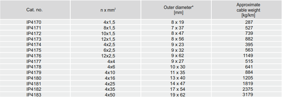
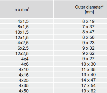
Available Configurations
The cable is available in core configurations from 4×1.5 mm² through to 4×50 mm² as standard sizes, including 8-core and 12-core arrangements for combined power and control applications. Non-standard core counts and cross-sections are available on request. The flat multi-core construction allows customisation of cable height and width dimensions to suit specific festoon hanger and C-track systems in upgrade and retrofit projects.
Compliance
The cable carries compliance with DIN VDE 0250-809 as the governing cable standard. Additional compliance includes RoHS 2015/863/EU confirming absence of restricted substances from all cable materials, LVD 2014/35/EU providing CE marking for equipment supplied to EU member states, and CPR 305/2011 covering installation as a permanent component of crane infrastructure assessed under construction product regulations.
Installation and Commissioning Checklist
Pre-Installation Checks
Confirm cable cross-section and core count matches the approved single-line drawing and load schedule
Verify delivery reel drum diameter is at least 20× the cable height H to prevent permanent kinking during storage
Confirm cable has not been stored below −30 °C or above +50 °C prior to installation
Inspect outer sheath across the full delivery drum length — any sheath cut deeper than 1 mm requires cable rejection before installation begins
Verify festoon rail is horizontal and level within ±3 mm over the full travel length before threading cable
Installation Checks
Confirm hanger bracket internal radius is greater than or equal to the minimum bending radius: 4×H or 5×H as applicable for the installed cable height
Thread cable through hangers without imposing twist — mark cable sheath with a chalk line along its length before threading to verify twist-free installation
Verify no twisted sections are present anywhere along the festoon run after threading is complete
Confirm proprietary strain relief grip is applied at both the fixed end and the moving end before any tensile load is applied to the cable
Verify cable sag is 10 to 15% of hanger spacing at mid-span with the trolley parked at the mid-travel position
Check that no cable touches an adjacent cable at any point across the full travel stroke
Commissioning Electrical Tests
Conductor DC resistance: measure each conductor and verify within ±5% of the calculated value for the installed cable length
Insulation resistance: measure each core to screen and core to core at 1 kV DC for 1 minute — accept 100 MΩ minimum for a new cable installation
Screen continuity: measure screen resistance end to end — accept 0.5 Ω maximum for the full installed festoon length
Hi-pot test: apply 3.5 kV AC for 5 minutes — no breakdown, no tracking, no sustained leakage current increase
EMC function test: operate all VFD drives simultaneously at full duty cycle and verify zero spurious faults on encoder, fieldbus, and safety system circuits within a 30-minute continuous run
Document and retain all test results as the baseline for annual condition monitoring and trending
Conclusion
The (N)GFLCGOEU-J screened flat rubber cable, manufactured to DIN VDE 0250-809, is the technically correct choice for festoon and guided-flex cable applications across the full range of port material handling equipment — from STS quay cranes and RTG/RMG container cranes through to ship loaders, stackers, and bulk reclaimers.
Its EPR insulation delivers the thermal range, chemical resistance, and low-modulus flexibility demanded by the cyclic bending in festoon systems. The heavy-duty type 5GM3 rubber sheath provides the mechanical durability and environmental resistance — oil, UV, ozone, and marine atmosphere — that open-air port installations impose over multi-decade service lives. The individual tinned copper wire braid screens with 85% coverage directly address the EMC vulnerability that VFD-intensive modern crane drives create for the sensitive encoder, fieldbus, and safety system wiring running alongside them.
Successful service life in demanding port applications depends not only on correct cable specification but on rigorous mechanical design of the festoon system, disciplined installation practice, and systematic commissioning testing followed by structured in-service condition monitoring. The mechanical stress analysis, installation guidance, failure mode review, and commissioning checklist in this guide provide a practical framework for engineers responsible for cable selection and system design on new port crane projects and major refurbishments.
For non-standard applications involving very high tensile loads, multi-axis bending, or extreme environmental conditions, a detailed cable-specific mechanical and thermal assessment is recommended before finalising the installation design.
Applicable standards: DIN VDE 0250-809 · EN 60228 / IEC 60228 · DIN VDE 0207-20/21 · DIN VDE 0293-308 · DIN VDE 0298-3/4 · EN 60811-404 · EN 60332-1-2 · IEC 61000-4-6 · RoHS 2015/863/EU · LVD 2014/35/EU · CPR 305/2011
Port crane cables | Mining cables | Reeling cables | Trailing cables | Festoon cables | Heavy-duty power cables | Medium voltage cables | Offshore crane cables | Underground mining cables | Dragline cables | Shearer cables | Container handling cables | STS crane cables | RTG cables | Mobile equipment cables | Armored cables | Flexible power cables | VFD cables | Submersible cables | Cold resistant cables | Abrasion resistant cables | Flame retardant cables | Marine environment cables | Opencast mining | Underground operations
© 2006 All rights reserved.
[INDUSTRIAL_CABLES]
INDUSTRIAL GRADE CABLE SYSTEMS | PORT & MINING SOLUTIONS
TEL: +86 153 7530 2641 |MAIL: hongjing.Wang@feichuncables.com