
(N)SHTOEU-J DIN VDE 0250-814 Rubber Reeling Cable: Durable Copper Design for High-Stress Crane and Port Equipment
Discover the (N)SHTOEU-J low voltage rubber reeling cable, certified to DIN VDE 0250-814, featuring finely stranded copper conductors and heavy-duty rubber sheathing for superior performance in demanding applications like stackers, reclaimers, and container handling equipment under tensile and torsional stress.
hongjing.Wang@Feichun
3/6/202610 min read
The Power Supply Challenge in Heavy Industrial Environments
Modern ports, stockyards, and heavy manufacturing facilities place extraordinary demands on electrical cables. Stackers, reclaimers, quay cranes, RTG (rubber-tyred gantry) cranes, RMG (rail-mounted gantry) cranes, and container handling equipment of all kinds require continuous power supply while in motion — meaning the cable must travel with the machine through every cycle of operation.
Standard fixed-installation cables cannot survive these dynamic conditions. Under repeated bending cycles, their conductors fracture. In sub-zero temperatures, their outer sheaths crack. Under torsional stress, their insulation fails. Each failure translates directly into unplanned downtime, expensive repair costs, and in worst-case scenarios, safety hazards.
The (N)SHTOEU-J reeling cable was engineered specifically to solve these challenges. Every layer of its construction — from conductor geometry to outer sheath compound — reflects a deliberate engineering decision driven by the realities of high-stress dynamic power supply. This document presents a detailed technical examination of how that design delivers reliable performance where standard cables cannot.
Cable Construction: A Layer-by-Layer Analysis
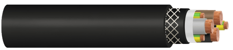
Conductors — IEC 60228 Class 5 Fine-Stranded Copper
Both the main power cores and the ground conductor use plain copper wires in a finely stranded configuration, conforming to IEC 60228 Class 5. This is the highest flexibility classification in the IEC conductor standard, achieved by using a large number of very fine individual wires with an optimised lay length.
Class 5 conductors distribute mechanical stress across thousands of fine strands rather than concentrating it in a small number of heavy wires. Under repeated bending and torsional cycles, the fine strands flex independently, dramatically extending fatigue life compared to Class 1 or Class 2 solid and stranded conductors. For applications where a cable may complete hundreds of thousands of reel cycles over its service life, this distinction is not marginal — it is fundamental to whether the cable survives at all.
Insulation — HEPR Compound per IEC 60502-1
Each conductor is insulated with HEPR (Hard Ethylene Propylene Rubber) compound meeting IEC 60502-1. This material was selected over alternatives such as PVC or standard XLPE for several critical reasons.
HEPR maintains its elasticity at temperatures as low as -40°C, where PVC insulation becomes brittle and prone to cracking under mechanical stress. At the upper end of the operating range, HEPR exhibits excellent thermal ageing resistance, sustaining its insulating properties at continuous conductor temperatures up to 90°C and withstanding short-circuit temperatures up to 250°C. The compound also offers strong resistance to ozone attack and UV degradation, making it suitable for unrestricted outdoor use without protective conduit.
Core identification follows DIN VDE 0293-308, with the ground conductor insulated in green-yellow in compliance with international safety standards.
Inner Sheath — Heavy-Duty Rubber Compound, Quality 5GM5
The inner sheath is formed from heavy-duty rubber compound conforming to quality grade 5GM5 per DIN VDE 0207-21. Critically, this sheath is applied so that it fills the interstices between the laid-up cores, creating a solid, void-free cross-section.
This filling serves two engineering functions. First, it prevents relative movement between cores under torsional loading, which would otherwise cause cores to migrate within the cable and distort its circular cross-section. Maintaining a round profile is essential for consistent winding behaviour on reels. Second, the filled inner sheath provides a uniform mechanical foundation for the reinforcement layer above it, ensuring the reinforcing braid engages evenly around the full circumference of the cable.
Reinforcement — Vulcanised Synthetic Fibre Braid
Between the inner and outer sheath sits a braid constructed from synthetic threads. What distinguishes this reinforcement layer from a simple mechanical wrap is the vulcanisation process: the braid is chemically bonded to both the inner and outer sheaths during manufacture, creating an integrated three-layer composite structure rather than three separate layers.
This vulcanised bond prevents delamination under repeated bending and torsional cycles — a failure mode commonly observed in cables where the outer sheath is simply extruded over a loose reinforcement. The braid itself distributes tensile loads across its woven structure, relieving the conductors of direct tensile stress during cable extension on motor-driven reels. It also significantly improves resistance to abrasion, tearing, and cut-through from sharp edges in industrial environments.
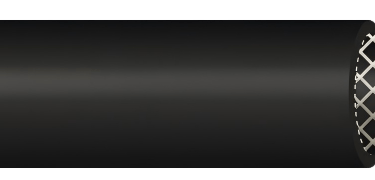
Outer Sheath — Heavy-Duty Rubber Compound, Quality 5GM5
The outer sheath uses the same 5GM5 heavy-duty rubber compound as the inner sheath. The black colouration provides maximum UV stability through carbon black loading, essential for cables exposed continuously to direct sunlight in outdoor port and stockyard installations. Inkjet marking on the outer surface provides clear type and specification identification for installation records and maintenance reference.
Technical Parameters and Performance Characteristics
Thermal Performance
The cable is rated for ambient temperatures from -40°C to +80°C in fixed installation, and from -30°C to +80°C in active reeling operation. The maximum permissible continuous conductor temperature is 90°C, with a short-circuit withstand temperature at the conductor of 250°C.
This wide thermal operating window means a single cable specification covers both cold-climate northern ports and hot-climate tropical terminals without modification. The -30°C lower limit for reeling operation accounts for the additional mechanical stress of bending a cable that has stiffened in cold conditions — an important distinction that is often overlooked in cable specification for polar or subarctic installations.
Mechanical Performance
The cable is rated for static tensile loads of 15 N/mm² and dynamic tensile loads of 30 N/mm², allowing the same cable to handle both the sustained tension of a hanging catenary and the transient shock loads that occur when a reel drive engages or reverses direction abruptly.
Torsional stress tolerance is ±25°/m, sufficient for the combined rotation experienced on the outreach arm of a stacker or reclaimer where the cable must follow both horizontal travel and boom luffing simultaneously.
Minimum bending radii are specified by application mode: 4× cable diameter for fixed installation, 6× cable diameter for reeling applications, 7.5× cable diameter at deflection pulleys, and a minimum spacing of 20× cable diameter where S-type directional changes occur. These graduated values reflect the differing mechanical demands of each configuration and are defined in accordance with DIN VDE 0298-3.
The maximum rated reeling speed of 180 m/min is a critical parameter for modern high-speed port equipment. Current generation RTG cranes and quay cranes can travel at large-wheel speeds that demand cable reel systems capable of operating at or beyond this threshold. Specifying a cable to this rating ensures the product is validated for the peak mechanical conditions it will actually encounter in service.
Electrical Performance
The rated voltage is 0.6/1 kV (U₀/U). The maximum permissible operating voltage is 0.7/1.2 kV in AC systems and 0.9/1.8 kV in DC systems, reflecting the voltage margin available for systems operating under transient overvoltage conditions. The AC withstand test voltage is 3.5 kV. Current-carrying capacities are determined in accordance with DIN VDE 0298-4 Table 15, with de-rating factors for thermal and reeling conditions applied per DIN VDE 0298-4.
Chemical and Environmental Resistance
Oil resistance meets DIN EN / IEC 60811-404, covering the hydraulic oils, lubricants, and fuel spills that are routine in heavy machinery environments. Flame retardancy conforms to DIN EN / IEC 60332-1-2, meaning the cable self-extinguishes after flame removal and resists longitudinal flame propagation — a key requirement in multi-cable trunking systems where a single ignition event must not spread along a cable run. Weather resistance covers ozone, UV radiation, and moisture, with no restriction on indoor or outdoor use.

Compatible Equipment Types and Motion Modes
Port Container Handling
Quay cranes (QC / STS cranes) use the cable to power gantry travel drives, with the cable paid out and retrieved as the crane traverses the quay. The cable must handle high-speed longitudinal extension at the full rated reeling speed, combined with the catenary sag tension during extended travel.
RTG cranes present a more complex loading scenario. The cable must follow both the gantry travel motion and accommodate the lateral displacement as the crane works across adjacent container rows. Spring-operated or motor-driven reels are typically used, with the cable subject to rapid reversals at the ends of each travel cycle.
RMG cranes on fixed rails impose a more predictable cyclic loading pattern, but the extended travel distances and high utilisation rates mean fatigue life becomes a dominant design criterion rather than peak load capacity.
Front loaders and straddle carriers require cables that combine high flexibility with resistance to ground contact and oil contamination — conditions that test both the mechanical and chemical properties of the outer sheath simultaneously.
Bulk Material Handling
Stacker and reclaimer machines impose arguably the most demanding combined loading conditions of any cable application. The cable must simultaneously accommodate linear travel along the stockyard rail, rotation of the slewing mechanism as the boom pivots in azimuth, and luffing of the boom as the working height changes. This three-axis motion produces the simultaneous tensile and torsional stress that the ±25°/m torsion rating and 30 N/mm² dynamic tensile rating are specifically designed to address.
Bucket wheel excavators and continuous ship unloaders present similar multi-axis loading conditions in applications where the consequences of cable failure are particularly severe, given the high production rates and difficult cable access during operation.
Reel Drive Compatibility
The cable is compatible with three reel drive systems in common industrial use. Motor-driven mono-spiral reels wind the cable in a single layer on a drum with a helical guide, providing precise tension control and suitability for the highest travel speeds. Motor-driven cylindrical reels accommodate greater cable storage length through multi-layer winding, at the cost of variable drum radius that the reel drive must compensate for. Spring-operated reels rely on stored spring energy for cable retrieval, providing a mechanically simple system for shorter travel distances where controlled take-up tension is acceptable.
Comparison with Standard Cable Types
The performance advantages of a purpose-designed reeling cable only become clear when compared against the alternatives that are sometimes used in their place.
Fixed-installation cables such as NYY or VV types use Class 1 or Class 2 conductors with hard copper stranding optimised for conductivity and compactness rather than flexibility. Their insulation and sheathing compounds are formulated for static thermal performance, not dynamic mechanical durability. In reeling applications, these cables typically fail within months through conductor fatigue fracture and insulation cracking — often long before any electrical fault is detected, creating a progressive degradation risk.
General-purpose flexible cables such as H07RN-F improve significantly on fixed-installation types in terms of conductor flexibility and sheath elasticity. However, they lack the reinforcement layer that distributes tensile loads away from the conductors, the 5GM5 compound rating that provides heavy-duty mechanical protection, and the specific validation for reeling speeds up to 180 m/min. They are appropriate for light to medium-duty portable equipment, but are not rated for the sustained dynamic loading of industrial reel systems.
The (N)SHTOEU-J differentiates itself from both categories through the combination of Class 5 conductors, HEPR insulation, 5GM5 inner and outer sheaths, and the vulcanised synthetic braid reinforcement — properties that collectively address tensile fatigue, torsional stress, abrasion, chemical exposure, and wide-temperature operation within a single unified construction.
Engineering Value: Service Life, Reliability, and Safety
Life Cycle Cost Perspective
The initial procurement cost of a purpose-engineered reeling cable exceeds that of a general-purpose alternative. However, the relevant cost comparison is not purchase price — it is total cost over the equipment service life.
In port operations, unplanned downtime on a quay crane or RTG is measured in operational impact per hour that far exceeds the value of the cable itself. A cable failure that necessitates equipment shutdown for replacement can idle a crane for a full shift. Where access to the cable requires dismantling of cable protection systems or working at height, the repair duration and associated costs increase further. A cable that delivers substantially greater service life between replacements reduces both the direct replacement cost and the far larger indirect cost of production interruption.
The 5GM5 outer sheath and vulcanised reinforcement layer also reduce the frequency of precautionary inspections and the rate of damage from ground contact, pinch points, and abrasive surfaces — maintenance interventions that consume technician time even when they do not result in cable replacement.
System Reliability
The combination of HEPR insulation and Class 5 fine-stranded conductors directly supports long-term electrical reliability. HEPR's thermal ageing resistance means insulation integrity at 90°C operating temperature degrades far more slowly than PVC, sustaining full rated current-carrying capacity over a longer service period. The conductor fatigue life under repeated bending and torsion significantly exceeds that of less flexible conductor classes, reducing the probability of progressive strand fracture that could go undetected until a full conductor failure occurs.
The interstice-filling inner sheath preserves the circular cross-section of the cable throughout its service life, ensuring consistent winding geometry on the reel drum. Cables that allow core migration and cross-section distortion under sustained torsional loading cause winding irregularities that accelerate mechanical wear and can lead to reel system faults independent of any electrical failure.
Safety Compliance
The cable carries compliance certifications covering RoHS 2015/863/EU (restriction of hazardous substances), LVD 2014/35/EU (low voltage directive), and CPR 305/2011 (construction products regulation). For equipment destined for the European market, this multi-directive compliance simplifies the equipment-level certification process and reduces the risk of compliance-related delays.
The EN 60332-1-2 flame retardancy rating is particularly important in applications where multiple cables share a common cable tray, duct, or festoon system. A single cable ignition event in a bundled installation could, with a non-flame-retardant cable, propagate along the entire cable run. The self-extinguishing behaviour required by EN 60332-1-2 contains the fire risk to the immediate point of fault.
The 250°C short-circuit conductor temperature withstand provides substantial thermal margin for the operation of upstream overcurrent protection devices. In high-impedance fault scenarios where fault current may be significantly below the full prospective short-circuit current, this margin reduces the probability of conductor burndown before protection operates.
Available Configurations and Selection Guidance
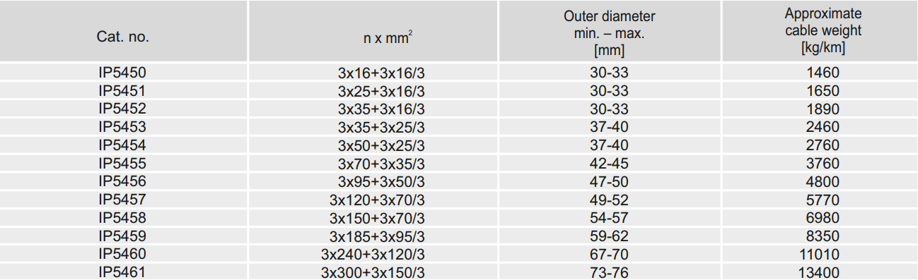
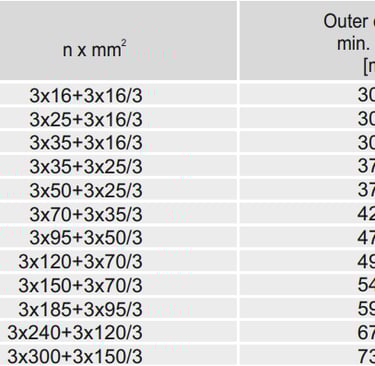
The cable is offered in twelve standard cross-section configurations. The smallest, 3×16+3×16/3 mm², has an outer diameter of 30–33 mm and an approximate weight of 1,460 kg/km, suitable for lighter auxiliary drive applications. At the upper end, 3×300+3×150/3 mm² reaches an outer diameter of 73–76 mm at approximately 13,400 kg/km, covering the main power feed requirements of the largest quay cranes and reclaimers.
Intermediate sizes — including 3×25, 3×35, 3×50, 3×70, 3×95, 3×120, 3×150, 3×185, and 3×240 mm² main core options — address the full range of drive motor ratings encountered across the crane and bulk handling sectors. The ground conductor cross-section scales proportionally with the main core size in each standard configuration.
Alternative designs, including configurations with cradle separators for specific reel geometries, are available on request for projects with non-standard requirements.
When selecting a cross-section, three parameters should be verified against the installation conditions. First, the maximum travel speed of the equipment must not exceed the cable's rated reeling speed of 180 m/min. Second, the minimum winding diameter on the reel drum must meet the applicable bending radius requirement — 6× the cable outer diameter for standard reeling, or 7.5× at deflection pulleys. Third, the ambient temperature range at the installation site must fall within the cable's rated thermal parameters for the intended operating mode.
Conclusion
The (N)SHTOEU-J reeling cable represents the application of systematic engineering discipline to one of the most demanding cable applications in industrial practice. Its construction does not reflect a single innovative feature — it reflects the integration of Class 5 copper conductors, HEPR insulation, 5GM5 heavy-duty rubber sheaths, and vulcanised synthetic reinforcement into a coherent design where each layer addresses specific failure modes observed in dynamic reeling service.
For engineers specifying power supply systems for port cranes, stockyard machines, or any heavy mobile equipment operating on motor-driven or spring-operated reels, the use of a cable validated to DIN VDE 0250-814 for this service is the most direct means of establishing that the cable selection is fit for purpose. The investment in a correctly specified reeling cable is recovered through extended service life, reduced maintenance intervention, and the avoidance of unplanned production downtime — outcomes that consistently outweigh the initial cost differential over any realistic equipment service life horizon.
Port crane cables | Mining cables | Reeling cables | Trailing cables | Festoon cables | Heavy-duty power cables | Medium voltage cables | Offshore crane cables | Underground mining cables | Dragline cables | Shearer cables | Container handling cables | STS crane cables | RTG cables | Mobile equipment cables | Armored cables | Flexible power cables | VFD cables | Submersible cables | Cold resistant cables | Abrasion resistant cables | Flame retardant cables | Marine environment cables | Opencast mining | Underground operations
© 2006 All rights reserved.
[INDUSTRIAL_CABLES]
INDUSTRIAL GRADE CABLE SYSTEMS | PORT & MINING SOLUTIONS
TEL: +86 153 7530 2641 |MAIL: hongjing.Wang@feichuncables.com