
NSHTOEU-J FO: The Complete Technical Guide to Heavy-Duty Reeling Cables for Crane and Port Applications
Explore NSHTOEU-J FO rubber reeling cable: 0.6/1kV crane cable with fiber optic option, oil/UV resistant, torsion ±25°/m, for stackers, reclaimers & port container handlers. DIN VDE 0250-814 compliant, extreme mechanical durability.
hongjing.Wang@Feichun
3/9/202611 min read
Introduction
In the world of heavy industrial cable engineering, few applications are as mechanically demanding as cable reeling on port cranes, stackers, and container-handling equipment. The NSHTOEU-J FO cable type has become a recognized standard for these environments — a rubber-insulated, low-voltage reeling cable that integrates optional fiber optic data transmission directly into a single, robust assembly.
This guide provides an in-depth technical breakdown of the NSHTOEU-J FO cable: its construction, electrical and mechanical specifications, applicable standards, fiber optic performance data, and the real-world conditions it is designed to endure. Whether you are an electrical engineer specifying cables for a new port terminal, a procurement specialist evaluating industrial cable products, or a technical buyer comparing crane cable solutions, this article provides the authoritative reference you need.
1. What Is the NSHTOEU-J FO Cable?
The NSHTOEU-J FO is a heavy-duty, low-voltage rubber reeling cable engineered for power supply combined with optional optical data transfer. It is based on DIN VDE 0250-814, the German standard governing flexible power cables for use in cable reeling systems.
The designation breaks down as follows:
N – Rubber-insulated (natural or synthetic rubber sheath)
SH – Heavy rubber sheathing (Schwergummi)
T – Used for torsional and tensile stress applications
O – Suitable for outdoor / external use
E – Suitable for use on cable reels and drums
U – Reinforced with a textile braid (Umflechtung)
J – Includes a protective (ground/PE) conductor
FO – Integrated fiber optic element
This naming convention follows established German/European cable designation logic, making it immediately recognizable to cable engineers across EU markets and international projects specifying DIN VDE standards.
2. Primary Application Areas
The NSHTOEU-J FO is designed specifically for mobile industrial equipment where the cable must withstand simultaneous tensile and torsional stress during continuous movement. Key application areas include:
Port container cranes, including ship-to-shore (STS), rubber-tyred gantry (RTG), and rail-mounted gantry (RMG) cranes
Stackers and reclaimers in bulk material handling terminals and stockyards
Container handling equipment of any kind in port and logistics environments
Motor-driven mono-spiral and cylindrical cable reel systems
Spring-operated reel drum installations
Mobile equipment in industrial yards, steel mills, and high-cycle logistics facilities
The FO variant is particularly valued in modern smart port and automated crane environments where real-time control data, sensor feedback, and monitoring signals need to travel alongside power — eliminating the need for separate data cabling runs and substantially reducing installation complexity and cost.


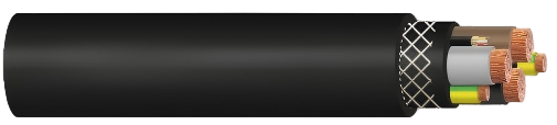
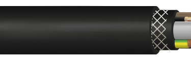
3. Detailed Construction Overview
3.1 Main Power Conductors
The main cores consist of plain copper wires in a finely stranded configuration, manufactured to IEC 60228 Class 5. Class 5 represents the finest stranding category in the IEC standard, providing maximum flexibility — critical in a cable that must endure thousands of bend cycles on a drum reel without conductor fatigue or breakage.
Conductor insulation uses HEPR (Hard Ethylene Propylene Rubber) compound conforming to IEC 60502-1. HEPR is selected for its thermal stability, dielectric properties, and resistance to ozone and UV degradation. Core colours follow DIN VDE 0293-308 standards, ensuring unambiguous identification during installation and maintenance.
3.2 Protective Ground Conductor
The protective ground conductor mirrors the main core construction: finely stranded Class 5 plain copper per IEC 60228, insulated with HEPR per IEC 60502-1. Its identification colour is green-yellow, universally mandated for PE conductors.
Importantly, the cross-section of the protective conductor is split into two halves, positioned in two of the three interstices formed between the main core assembly. This design feature maintains cable roundness, prevents internal shifting during torsional stress, and optimizes overall flexibility across the full bend radius range.
3.3 Fiber Optic Element
The fiber optic element occupies the third interstice within the cable assembly, taking advantage of the geometric space between power cores without increasing overall cable diameter. Two standard bundle configurations are available: 12 fibers in a single FO element, or 2×12 fibers in a dual FO bundle configuration (designated by the "2×12FO" suffix in product references).
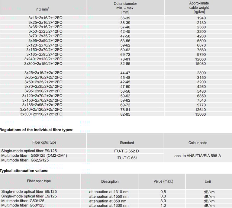
Three fiber types are supported to accommodate different network infrastructure requirements. The E9/125 single-mode fiber conforms to ITU-T G.652 D and is used for long-distance, high-bandwidth links. The G50/125 multimode fiber follows ITU-T G.651 and ANSI/TIA/EIA 598-A, covering OM2 through OM4 applications over short to medium distances. The G62.5/125 multimode fiber, also per ANSI/TIA/EIA 598-A, supports legacy multimode systems where this fiber diameter is already in use. Custom fiber type combinations are available on request, allowing engineers to precisely match existing network infrastructure.
3.4 Inner Sheath
The inner sheath is formed from heavy-duty rubber compound, quality designation 5GM5, conforming to DIN VDE 0207-21. The compound is applied to fill all interstices between the cable elements, creating a solid, void-free core that prevents moisture ingress and ensures the assembly behaves as a unified mechanical unit during bending and torsional loading.
3.5 Reinforcement Braid
A braid of synthetic threads is applied over the inner sheath. The braid is co-vulcanized — chemically bonded — into the rubber material between the inner and outer sheaths. This creates a monolithic composite structure rather than independent layers, which is critical for torsion resistance. The reinforcement prevents the outer sheath from ballooning or separating under combined tensile and torsional loads, a failure mode common in unreinforced cables operating on high-speed reels.
3.6 Outer Sheath
The outer sheath uses the same 5GM5 heavy-duty rubber compound as the inner sheath, per DIN VDE 0207-21. The standard colour is black, with inkjet marking for cable identification. The rubber compound provides the cable's primary environmental protection: oil resistance, UV stability, ozone resistance, and mechanical abrasion protection. An optional version with a cradle separator (K variant) is available on request for applications requiring additional positional stability of internal elements.
4. Electrical Specifications
The NSHTOEU-J FO operates at a rated voltage of 0.6/1 kV (U₀/U), placing it firmly in the low-voltage category suitable for the majority of crane drive and control power applications.
The maximum permissible AC operating voltage is 0.7/1.2 kV, and the maximum permissible DC operating voltage is 0.9/1.8 kV. The AC test voltage is 3.5 kV, confirming the integrity of insulation under impulse conditions. Current-carrying capacities are determined per DIN VDE 0298-4, Table 15, and de-rating factors for both thermal load and reeling duty are applied in accordance with the same standard.
Engineers should calculate actual current capacity by applying the appropriate de-rating factors for ambient temperature, installation method, and the number of cable layers wound on the reel drum, as bunching significantly reduces heat dissipation.
5. Thermal Specifications
The NSHTOEU-J FO is rated for operation across a wide temperature range, covering both arctic port environments and high-temperature industrial sites. For fixed installations, the permitted ambient temperature range is -40 °C to +80 °C. For dynamic reeling operation, the range is -30 °C to +80 °C.
The maximum permissible continuous conductor temperature is 90 °C. During short-circuit events, the conductor can withstand a maximum temperature of 250 °C without permanent damage to the insulation system.
The 10 °C difference in minimum operating temperature between fixed and reeling duty reflects the increased mechanical stress on rubber materials in motion at extreme cold. HEPR and 5GM5 rubber maintain acceptable flexibility above -30 °C for dynamic applications, but become stiffer at lower temperatures — which is acceptable for static installations where bending cycles are not occurring.
6. Mechanical Specifications
Mechanical performance is where the NSHTOEU-J FO distinguishes itself from standard flexible cables. The static tensile load rating is 15 N/mm², and the dynamic tensile load rating is 30 N/mm² — double the static figure. This doubling reflects real-world reel operation where cable acceleration and deceleration create load spikes well above steady-state tension values, particularly at the start and stop of reel cycles.
Torsional stress tolerance is ±25 °/m, critical for rotary applications or cable paths that include axis changes. Exceeding this value risks conductor fatigue and sheath cracking over time and must be factored into reel geometry design.
The maximum reeling speed is 180 m/min, covering the operational requirements of the fastest motor-driven crane reel systems in use at major container terminals today.
Bending radii per DIN VDE 0298-3 are specified for each installation scenario. For fixed installations, the minimum bending radius is 4× the cable outer diameter. For reeling applications, it is 6× the cable outer diameter. At deflection pulleys, the minimum increases to 7.5× the cable outer diameter. For S-type directional changes — where the cable path reverses direction around two opposing pulleys — the minimum distance between the two reversal points must be at least 20× the cable outer diameter. This last parameter is one of the most frequently overlooked in reel system design and, when violated, causes premature sheath and insulation failure at the reversal point.
7. Fiber Optic Performance Data
The integrated fiber optic elements meet standard industrial attenuation requirements. For E9/125 single-mode fiber, the maximum attenuation is 0.5 dB/km at 1310 nm and 0.3 dB/km at 1550 nm. For G50/125 multimode fiber, maximum attenuation is 3.0 dB/km at 850 nm and 1.0 dB/km at 1300 nm. For G62.5/125 multimode fiber, maximum attenuation is 3.5 dB/km at 850 nm and 1.5 dB/km at 1300 nm.
These values are consistent with the performance requirements of industrial Ethernet, PROFIBUS FO, and similar industrial communication protocols. System designers should verify total link budget — combining cable attenuation with connector insertion losses — against the receiver sensitivity specification of the chosen communication equipment to ensure sufficient optical power margin across the full cable length and over the service life of the installation.
8. Chemical and Environmental Resistance
The NSHTOEU-J FO is engineered for unrestricted deployment in both indoor and outdoor environments, with no limitations on continuous outdoor exposure.
Oil resistance is tested and certified per DIN EN / IEC 60811-404, which is essential in port and crane environments where hydraulic fluid and lubricant exposure is a routine operational reality. Fire behaviour is rated flame retardant per DIN EN / IEC 60332-1-2, ensuring that individual cable installations do not propagate flame along the cable run — a critical safety requirement in cable tray and festoon installations on crane structures.
Weather resistance is unrestricted. The cable withstands ozone, UV radiation, and moisture continuously, which is critical for cables installed on open-air crane structures exposed to direct sunlight, salt spray in coastal port environments, and precipitation across all seasons. The 5GM5 rubber compound used in both sheaths is specifically formulated for these multi-factor environmental demands, maintaining flexibility and mechanical integrity across the full operating temperature range even after prolonged UV exposure.
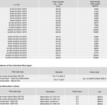
9. Available Cross-Sections and Configurations
The NSHTOEU-J FO is manufactured in a wide range of conductor cross-sections to meet different power requirements. The single FO bundle (12FO) configurations span from 3×16+2×16/2 mm² (outer diameter 36–39 mm, approximately 1,940 kg/km) through to 3×300+2×150/2 mm² (outer diameter 82–85 mm, approximately 15,080 kg/km). The intermediate cross-sections cover 25, 35, 50, 70, 95, 120, 150, 185, and 240 mm² main conductors, with protective conductor cross-sections scaled proportionally.
Dual fiber optic bundle configurations (2×12FO) are available for the same conductor cross-sections, with slightly larger outer diameters to accommodate the second FO bundle. Approximate weights for these configurations are comparable to their single-FO equivalents at each cross-section size.
Custom cross-sections and core count configurations can be produced on request, allowing the cable to be precisely specified for projects with non-standard power requirements or unusual reel drum geometries.
10. Applicable Standards and Certifications
The NSHTOEU-J FO is designed and manufactured in compliance with a comprehensive set of international and European standards. The primary cable standard is DIN VDE 0250-814, governing low-voltage cables for reeling systems. Conductor construction follows IEC 60228 Class 5 for finely stranded flexible copper. Insulation compound specification is per IEC 60502-1 for HEPR material. Sheath compound is per DIN VDE 0207-21 for the 5GM5 heavy-duty rubber quality. Core colour identification follows DIN VDE 0293-308.
Minimum bending radii are validated per DIN VDE 0298-3, and current capacity calculations and de-rating methodology follow DIN VDE 0298-4. Oil resistance is tested per DIN EN / IEC 60811-404, and flame retardancy is verified per DIN EN / IEC 60332-1-2.
On the fiber optic side, single-mode E9/125 fiber complies with ITU-T G.652 D, while G50/125 multimode fiber conforms to ITU-T G.651 and ANSI/TIA/EIA 598-A colour coding standards.
From a regulatory compliance perspective, the cable meets the requirements of the EU Low Voltage Directive (LVD 2014/35/EU), the Construction Products Regulation (CPR 305/2011), and the RoHS Directive (2015/863/EU) restricting hazardous substances.
11. Engineering Considerations for System Design
11.1 Reel Selection and Cable Tensioning
The cable is compatible with both motor-driven mono-spiral/cylindrical reels and spring-operated reels. When designing reel systems, engineers should verify that tensioning systems maintain cable tension within the static load limit of 15 N/mm² during the pay-out phase, and prevent slack conditions that could cause uncontrolled coiling or mechanical abrasion on the drum flanges.
11.2 S-Type Directional Changes
The 20× cable outer diameter minimum distance requirement for S-type directional changes is one of the most frequently overlooked design parameters in crane cable tray and festoon system engineering. In systems where the cable path reverses direction around deflection pulleys in opposing orientations, the physical distance between the two reversal points must be at least 20× the cable outer diameter. Failing to provide this clearance creates a localized high-stress bending zone that accelerates sheath and insulation degradation regardless of cable quality.
11.3 Fiber Optic Termination
The fiber optic elements must be terminated with industrial-grade connectors rated for the vibration, shock, and temperature cycling environment of crane applications. For new installations, SC/APC or LC/APC connectors are commonly specified for single-mode systems; SC or LC connectors are standard for multimode. Field termination in harsh environments should use pre-polished or splice-on connector types to ensure reliable attenuation performance without the need for polishing equipment in the field.
11.4 Temperature De-rating for Reeling Duty
At elevated ambient temperatures above 30 °C, current-carrying capacity must be de-rated per DIN VDE 0298-4. Cable bunching on the reel drum — where multiple wound layers reduce heat dissipation from the inner layers — introduces additional thermal resistance not present in the standard tabulated values. Reel drum design should account for adequate ventilation, or the additional thermal resistance of wound cable layers must be explicitly factored into cross-section selection calculations.
12. Comparison with Standard NSHTOEU Cable Variants
The NSHTOEU-J FO belongs to the broader NSHTOEU cable family. The standard NSHTOEU-J variant provides the same power core construction, protective conductor configuration, and mechanical ratings, but without the integrated fiber optic element in the third interstice. The NSHTOEU-J FO adds the FO bundle (12 or 2×12 fibers) in that interstice without changing the fundamental cable geometry or mechanical performance characteristics.
This integration approach eliminates the need for a separate fiber optic trailing cable alongside the power cable on crane and reel systems. Running two separate cables — one for power, one for data — doubles the mechanical load on the reel drum, complicates cable management, and introduces an additional potential failure point in the system. The integrated FO design reduces installation cost, simplifies reel drum sizing, and provides a single termination assembly at each end of the cable run.
Conclusion
The NSHTOEU-J FO is a highly engineered product that addresses one of industrial cable engineering's most demanding use cases: simultaneous high-current power delivery and fiber optic data transmission in a cable assembly that must endure continuous mechanical cycling under combined tension, torsion, and bending loads.
Its compliance with DIN VDE 0250-814 and the breadth of supporting IEC, EN, and ITU standards make it the cable of choice for port cranes, stackers, reclaimers, and any mobile equipment requiring dependable heavy-duty reeling performance. The availability of multiple conductor cross-sections from 16 mm² to 300 mm², three supported fiber types, and custom configurations on request ensures that the NSHTOEU-J FO can be precisely specified to meet the requirements of any project, from a single crane upgrade to a full greenfield port terminal build.
For engineers designing or upgrading crane electrical systems, the NSHTOEU-J FO represents a technically sound, standards-compliant, and operationally proven solution that consolidates power and data into a single, mechanically robust cable assembly.
Keywords: NSHTOEU-J FO cable | DIN VDE 0250-814 | crane reeling cable | low voltage fiber optic cable | port crane cable | torsion resistant cable | rubber reeling cable | IEC 60228 class 5 | HEPR insulation | container terminal cable
Port crane cables | Mining cables | Reeling cables | Trailing cables | Festoon cables | Heavy-duty power cables | Medium voltage cables | Offshore crane cables | Underground mining cables | Dragline cables | Shearer cables | Container handling cables | STS crane cables | RTG cables | Mobile equipment cables | Armored cables | Flexible power cables | VFD cables | Submersible cables | Cold resistant cables | Abrasion resistant cables | Flame retardant cables | Marine environment cables | Opencast mining | Underground operations
© 2006 All rights reserved.
[INDUSTRIAL_CABLES]
INDUSTRIAL GRADE CABLE SYSTEMS | PORT & MINING SOLUTIONS
TEL: +86 153 7530 2641 |MAIL: hongjing.Wang@feichuncables.com