(N)TMCGCW11Y: Engineering the Next-Generation Flexible Medium Voltage Cable for Cranes, Mining and Offshore Systems
A deep-dive into the design philosophy, material science, and application engineering behind a DIN VDE 0250-813 compliant high-flexibility screened single-core MV cable.
CRANE CABLE
hongjing.Wang@Feichun
3/5/202612 min read
1. The Engineering Challenge: Why Standard MV Cables Fall Short
Medium voltage cables in cranes, mining operations and offshore power systems operate under conditions that impose simultaneous mechanical, thermal, chemical and electrical stresses far beyond what a conventional MV cable is designed to handle. A port gantry crane, for example, subjects its power cable to thousands of bending cycles per day at trolley speeds up to 240 m/min, while the cable must simultaneously tolerate lubricant contamination, sub-zero temperatures, and maintain full electrical integrity at rated voltage.
Conventional XLPE-insulated MV cables are engineered for static burial or fixed tray installations. They tolerate bending during installation but are not designed for continuous dynamic flexing, high tensile loads, or aggressive chemical exposure. When such cables are pressed into service on crane cable carriers or shore-power reeling systems, the failure sequence is predictable: insulation micro-cracking, shield wire fatigue fracture, outer sheath abrasion, and ultimately in-service electrical failure—often at the worst possible operational moment.
The fundamental design objective for a true flexible MV cable is not merely to survive a few extra bending cycles, but to deliver reliable, long-term performance across hundreds of thousands of flex operations without degradation in either electrical or mechanical properties. The (N)TMCGCW11Y addresses this challenge through a deliberate, layered engineering architecture in which each construction element solves a specific failure mechanism.
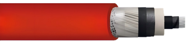
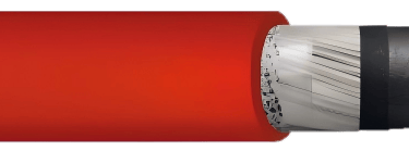
2. Cable Structure and Construction: A Layered Engineering Architecture
The (N)TMCGCW11Y is a single-core, screened, flexible medium voltage cable standardised under DIN VDE 0250-813. Its cross-section is not a single design decision but a hierarchy of interdependent functional layers, each resolving a distinct engineering problem.
2.1 The Conductor: Class 5 Finely Stranded Tinned Copper
At the core is a finely stranded tinned copper conductor conforming to Class 5 of DIN EN / IEC 60228—the highest flexibility class for power cable conductors. Class 5 conductors are assembled from a large number of very fine individual copper wires, which distribute bending strain across hundreds of wire elements rather than concentrating it in a few thick strands. This approach dramatically reduces metal fatigue at each individual wire during repeated flexing and is the primary reason Class 5 conductors outlast Class 2 conductors by a substantial margin in dynamic applications.
The tin coating applied to each copper wire serves two purposes. First, it forms an electrochemical barrier that prevents surface oxidation at inter-strand contact interfaces, preserving low contact resistance throughout the cable's service life. Second, it reduces galvanic corrosion risk in the moisture-rich environments typical of offshore and mining installations. Mechanically, the tin layer acts as a micro-lubricant between adjacent wires during bending, reducing inter-strand friction and progressive wear.
2.2 The Three-Layer Insulation System
The insulation system consists of three precisely engineered sub-layers, rather than the simple homogeneous dielectric used in a standard static MV cable.
The inner semi-conductive stress control layer is applied directly over the conductor. This conductive polymer layer eliminates the air voids that would otherwise exist between the irregular surface of a stranded conductor and the main insulation body. In a medium voltage cable, air voids are sites of partial discharge (PD) activity—localised electrical breakdown events that progressively erode the surrounding insulation. By conformally filling the conductor surface with a semi-conductive material of matched permittivity, the electric field at the conductor interface is homogenised, suppressing PD initiation and protecting the main insulation from internal erosion.
The EPR insulation compound, formulated to DIN VDE 0207-20, forms the primary dielectric. Ethylene Propylene Rubber is the insulating material of choice for flexible MV cables precisely because of properties that XLPE cannot replicate. EPR has an inherently amorphous, rubbery polymer matrix that retains mechanical flexibility across a wide temperature range without the crystalline phase transitions that make XLPE brittle at sub-zero temperatures. EPR also exhibits superior resistance to water treeing—a progressive long-term degradation mechanism that is the primary cause of premature dielectric failure in moisture-exposed XLPE cables—owing to its lower water absorption and inherently hydrophobic surface chemistry.
The outer semi-conductive insulation shield is applied over the EPR layer. Analogous in function to the inner stress control layer, it provides a smooth, equipotential cylindrical surface at the outer boundary of the dielectric. This ensures that the electric field transitions uniformly into the metallic ground screen above it, preventing field intensification at any local surface irregularity in the insulation—a potential source of partial discharge from the outside of the dielectric inward.
2.3 The Concentric Ground Screen
Over the three-layer insulation system sits a concentric ground conductor assembled from tinned copper wire strands, providing approximately 85% coverage of the insulation surface. This screen performs two simultaneous functions: it acts as an electrostatic shield, containing the cable's electric field within the insulation and preventing inductive interference with adjacent circuits, and it provides a defined protective earth conductor path in the event of a phase-to-earth fault.
The 85% coverage specification represents a carefully balanced engineering trade-off. Higher coverage would improve shielding effectiveness and fault current capacity, but would create a rigid, locked-screen structure that resists bending and concentrates mechanical stress on the wire strands during flexing. The remaining 15% of open window allows the screen wires to redistribute slightly under bending loads, preventing progressive wire fatigue without compromising the screen's electrical continuity. Tinned copper is specified for the screen wires for the same corrosion resistance rationale applied to the conductor.
2.4 The Polyether-Based PUR Outer Sheath
The outer sheath is the most application-specific element of the construction. Standard MV cable sheaths use PVC or polyethylene compounds selected for UV resistance and low cost in static installations. The (N)TMCGCW11Y instead uses a thermoplastic polyether-based polyurethane compound per EN 50363-10-2—a material selection with significant engineering consequences.
Polyether-PUR was chosen because it uniquely combines a set of mechanical and chemical properties that no single alternative sheath material can match. Its abrasion resistance is several times superior to PVC, which is critical for cables moving continuously through steel cable carrier chains at speeds up to 240 m/min. Its elastic recovery means that surface deformation from contact with carrier guide bars is largely reversible, preventing the progressive wear groove formation that eventually exposes the screen in abrasion-damaged PVC-sheathed cables. Critically, the polyether backbone—as opposed to a polyester backbone—is resistant to hydrolytic degradation in the mixed oil-and-water environments found in crane machinery houses and mining headings. The sheath is coloured red for immediate field identification.

3. Material Performance Advantages
The material choices described above translate into a defined set of measurable performance advantages that directly address the failure modes of conventional MV cables in dynamic service.
3.1 Thermal Performance
The cable is rated for ambient temperatures from –50 °C to +90 °C in fixed installation and from –40 °C to +90 °C in flexible operation, with a maximum permissible continuous conductor temperature of 90 °C and a short-circuit conductor temperature limit of 200 °C.
The –40 °C lower limit for flexible operation is a direct consequence of EPR insulation and PUR sheath selection. At this temperature, EPR retains sufficient elasticity to flex without micro-cracking—a property that XLPE and PVC sheaths cannot reliably match. The –50 °C limit for fixed installation extends the cable's passive service range to arctic environments where even static cables in switchgear must survive extreme cold without sheath embrittlement.
3.2 Electrical Ratings
The cable is available across five rated voltage classes spanning 3.6/6 kV through to 18/30 kV, covering the full range of medium voltage systems used in industrial crane, mining and offshore power applications. Each voltage class carries corresponding maximum permissible AC and DC operating voltages and AC test voltages per DIN VDE 0250-813. De-rating factors for non-standard installation methods are applied per DIN VDE 0298-4.
3.3 Mechanical Ratings
The maximum tensile load of 15 N/mm² per conductor cross-section supports the cable's own weight plus dynamic acceleration loads in crane carrier and reeling applications without conductor creep or insulation displacement. The minimum bending radius of ≥ 6 × outer diameter for fixed installation and ≥ 8 × outer diameter for free-moving dynamic service is significantly tighter than the minimum bend radii specified for conventional static MV cables, enabling compact routing in switchgear enclosures and crane superstructures. Movement speeds of 6 m/min for shore-power reeling systems and 70–240 m/min for crane energy chains define the cable's validated dynamic duty envelope.
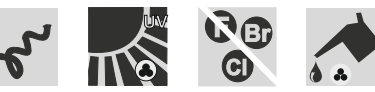
3.4 Chemical and Environmental Resistance
The polyether-PUR sheath provides a specific resistance profile that sets it apart from alternative sheath materials in four key areas.
Oil resistance to DIN EN / IEC 60811-404 is achieved through the polyether backbone chemistry, which withstands aliphatic hydrocarbons including mineral oils and hydraulic fluids. Unlike polyester-PUR, polyether-PUR does not hydrolyse in mixed oil-water environments—a condition routinely encountered in crane machinery compartments and mining equipment.
The halogen-free composition per DIN EN / IEC 60754-1 means that in the event of fire, the sheath does not emit hydrogen chloride or other halogen acid gases. In confined spaces such as ship holds, underground mining galleries and enclosed crane cabs, HCl emission could incapacitate personnel and cause irreversible corrosive damage to electrical equipment. Halogen-free sheath chemistry removes this risk entirely.
Flame retardant behaviour to DIN EN / IEC 60332-1-2 ensures that a localised ignition event does not propagate along the cable run—an important containment property in installations where large lengths of cable are routed through common pathways.
Water resistance to protection class Ad8 certifies the cable for permanent submersion at pressures up to 10 bar, equivalent to approximately 100 m of water depth, making it suitable for subsea cable runs and permanently flooded mining environments.
4. Applicable Crane Types and Motion Profiles
The (N)TMCGCW11Y's performance envelope maps precisely onto the crane types and motion systems that impose the most demanding cable duties.
4.1 Port and Intermodal Gantry Cranes — Energy Chain Systems
Ship-to-shore (STS), rubber-tyred gantry (RTG) and rail-mounted gantry (RMG) cranes supply power to their traversing trolleys via cable carrier chains. In a high-throughput port, an STS crane trolley may complete 500–700 cycles per day across spans of 40–60 m, achieving cable movement speeds in the 70–240 m/min range. Over a 10–15 year crane service life, the cable accumulates millions of flex cycles. The tight free-moving bending radius (≥ 8 × OD) allows integration into compact carrier systems without exceeding the cable's mechanical limits, while the PUR sheath tolerates the continuous abrasive contact with carrier guide and filler bars.
4.2 Shore Power Systems for Container Vessels
Shore-to-ship power (SSP) connections supply MV power—typically 6.6 kV or 11 kV—to vessels at berth, replacing onboard diesel generators. The cable between the quayside supply point and the vessel's inlet box is repeatedly deployed and retrieved as vessels arrive and depart, via a reeling system or cable management trolley at movement speeds around 6 m/min. The flexibility requirement is lower in terms of speed but higher in terms of bending radius variability, as the cable must accommodate the vessel's deck height relative to the quayside connection, which varies with tide and cargo load. The single-core screened construction avoids the inter-core mechanical interaction that complicates the flexing behaviour of multi-core cables in reeling duty.
4.3 Mining Hoists, Draglines and Rope Shovels
Underground and surface mining equipment operates in conditions that combine extreme low temperatures, high mechanical stress, constant oil and water contamination, and occasional impact loading. The –40 °C flexible operation rating and 15 N/mm² tensile limit make the cable suitable for this environment, while the Ad8 water resistance rating ensures cable integrity in flooded headings and wet surface operating conditions.
4.4 Switchgear and Transformer House Connections
Within MV switchgear rooms and transformer houses, space constraints frequently require cable routing with tight bends at termination points. The fixed bending radius of ≥ 6 × OD allows routing configurations that would impose excessive mechanical stress on a conventional cable with a larger minimum bend radius, simplifying installation in congested enclosures without requiring over-sized cable bays.

5. Comparison with Standard MV Cable Constructions
The (N)TMCGCW11Y is not a marginal improvement on a standard MV cable but a purpose-designed product category. Understanding this distinction matters for engineering specification decisions.
A standard static MV cable uses a Class 1 (solid) or Class 2 (stranded) conductor, XLPE insulation, and a PVC or PE outer sheath. Its minimum bending radius is defined for one-time installation only and is not rated for dynamic flexing. Its lower limit for service in fixed installation is typically around –20 °C to –30 °C, and its sheath offers no meaningful oil resistance. In a crane energy chain or reeling application, a standard cable will fail—the only engineering uncertainty is how quickly.
In contrast, the (N)TMCGCW11Y's Class 5 conductor distributes bending strain across a maximum wire population. Its EPR insulation maintains dielectric integrity and mechanical flexibility at temperatures and bending radii at which XLPE would crack. Its polyether-PUR sheath resists the combined abrasion, oil and hydrolysis attack that destroys PVC sheaths in dynamic industrial service. Its three-layer insulation system eliminates the partial discharge activity that causes progressive dielectric erosion in cables with air voids at the conductor interface.
A key technical differentiator is EPR's superior resistance to water treeing compared to XLPE. In applications where any moisture ingress is possible—which includes virtually all outdoor, offshore and mining installations—the long-term dielectric integrity of an EPR cable substantially exceeds that of an XLPE cable under identical electrical stress conditions. This is not a marginal advantage: water tree failures in XLPE cables account for a significant proportion of in-service MV cable faults in humid environments.
Attempting to substitute a standard XLPE/PVC cable in a crane energy chain or reeling application does not simply reduce the available performance margin. It fundamentally mismatches the cable's design basis with the application's loading conditions, producing accelerated and largely unpredictable failure behaviour.
6. Engineering Value: Lifetime, Reliability and Safety
6.1 Lifecycle Cost
The initial material cost of an EPR/PUR flexible MV cable is higher than a comparable XLPE/PVC static cable. This differential is frequently used to justify specifying the cheaper alternative, but a lifecycle cost analysis consistently reverses this conclusion when the full cost of ownership is considered.
In a crane energy chain application, a standard cable typically requires replacement every two to three years. A purpose-designed flexible cable operating within its mechanical specification achieves service lives of eight to twelve years or longer. When the cost of replacement is loaded with crane downtime—typically several thousand dollars per hour for a container crane—plus labour for cable threading and termination, plus the indirect cost of scheduling maintenance around vessel arrivals and port operations, the economic case for the higher-specification cable becomes decisive, not marginal.
6.2 Failure Mode Elimination
The design of the (N)TMCGCW11Y directly addresses each primary failure mechanism observed in MV cables in dynamic service. Insulation cracking at low temperature is eliminated by EPR insulation flexibility to –40 °C. Conductor wire fatigue fracture is mitigated by the Class 5 finely stranded construction distributing bending strain across the maximum wire population. Partial discharge erosion is controlled by the three-layer insulation system providing void-free interfaces at both conductor and screen boundaries. Sheath abrasion failure is resisted by the high-abrasion-resistance polyether-PUR compound. Screen wire fatigue is managed by the 85% coverage design allowing controlled redistribution under bending without loss of screen continuity. Chemical attack on the sheath is prevented by the polyether-PUR oil and hydrolysis resistance.
By addressing all primary failure modes within the design, the cable reduces the probability of unplanned failure events that in crane and offshore applications carry both economic and safety consequences.
6.3 Safety
MV cable failures in operating machinery carry risks beyond the direct cost of cable replacement. A phase-to-earth fault on a crane supply cable can produce arc flash events with sufficient energy to injure personnel and damage adjacent equipment. A cable fire in a confined machine room or vessel hold can escalate rapidly and produce toxic atmospheres.
The screened construction provides a defined, low-impedance fault current path that enables overcurrent protection to operate and clear faults quickly, minimising arc fault energy released at the fault location. The halogen-free, flame retardant sheath limits fire propagation and avoids the toxic and corrosive gas emission associated with PVC sheath combustion, protecting personnel and sensitive electronic equipment in enclosed spaces. The Ad8 water resistance rating eliminates the risk of moisture-induced insulation failure—one of the primary causes of single-phase faults on MV cables in outdoor and marine environments.
Compliance with RoHS 2015/863/EU and CPR 305/2011 ensures that the cable meets EU requirements for hazardous substance restrictions and construction product performance declarations, simplifying project approval in regulated industries and port environments.
6.4 Cross-Section Selection
The cable is available from 1×25/16 mm² through to 1×300/25 mm² (conductor/screen) across all rated voltage classes. Current-carrying capacities are calculated per IEC 60364-5-52 at 90 °C conductor temperature, 30 °C reference ambient, free in air, three loaded conductors in trefoil—conditions representative of crane carrier installations. Selection of the correct cross-section requires consideration of the load current profile including drive starting currents, the installation method and associated de-rating factors, the ambient temperature range, the permissible voltage drop across the cable run, and the mechanical tensile load imposed by cable weight and dynamic accelerations in reeling or carrier systems.
7. Conclusion
The (N)TMCGCW11Y represents the application of systematic materials engineering and application-specific design thinking to a problem that conventional MV cable technology cannot adequately solve. Its Class 5 tinned copper conductor, three-layer EPR insulation system, 85%-coverage concentric screen, and polyether-PUR sheath are not independent specifications but an integrated design solution in which each element reinforces the performance of the others.
For specifying engineers, procurement teams and asset managers responsible for crane power systems, mining operations and offshore infrastructure, the conclusion is clear: the incremental cost of a properly engineered flexible MV cable is recovered many times over through reduced replacement frequency, elimination of unplanned downtime, and avoidance of the safety and liability consequences associated with in-service cable failure in critical machinery.
As port throughput demands intensify, crane duty cycles increase, and offshore power regulations tighten, the performance margins built into a purpose-designed flexible MV cable will increasingly differentiate reliable operations from those constrained by an under-specified cable infrastructure.
Standards referenced: DIN VDE 0250-813 | DIN VDE 0207-20 | DIN VDE 0250-1 | DIN VDE 0298-4 | EN 50363-10-2 | DIN EN/IEC 60228 | IEC 60364-5-52 | DIN EN/IEC 60811-404 | DIN EN/IEC 60332-1-2 | DIN EN/IEC 60754-1 | RoHS 2015/863/EU | CPR 305/2011
Port crane cables | Mining cables | Reeling cables | Trailing cables | Festoon cables | Heavy-duty power cables | Medium voltage cables | Offshore crane cables | Underground mining cables | Dragline cables | Shearer cables | Container handling cables | STS crane cables | RTG cables | Mobile equipment cables | Armored cables | Flexible power cables | VFD cables | Submersible cables | Cold resistant cables | Abrasion resistant cables | Flame retardant cables | Marine environment cables | Opencast mining | Underground operations
© 2006 All rights reserved.
[INDUSTRIAL_CABLES]
INDUSTRIAL GRADE CABLE SYSTEMS | PORT & MINING SOLUTIONS
TEL: +86 153 7530 2641 |MAIL: hongjing.Wang@feichuncables.com