
(N)TSCGEW11Y 6/10 kV Halogen-Free Reeling Cable for Shore Power Connections
Discover the (N)TSCGEW11Y 6/10 kV halogen-free reeling cable, designed for shore power connections in HVSC systems per IEC/ISO/IEEE 80005-1 standards. Explore thermal, mechanical, and electrical specs for reliable marine applications like container vessels and cruise liners.
CRANE CABLE
hongjing.Wang@Feichun
3/4/202613 min read
Why Shore Power Demands a Cable in a Category of Its Own
As the maritime industry accelerates toward decarbonization, High Voltage Shore Connection (HVSC) systems have become a cornerstone technology for eliminating shipboard emissions during port calls. While the environmental case for cold ironing is well established, the cable itself — the physical link between quayside switchgear and the vessel's onboard grid — remains the most mechanically demanding component in the entire system.
Standard land-based high-voltage cables are optimized for static, thermally stable, buried or trunked installations designed to serve for decades without movement. Shore power reeling cables face an entirely different physics problem. They must maintain 6/10 kV insulation integrity while being mechanically cycled through thousands of reel-in and reel-out operations, exposed to salt spray, UV radiation, oil contamination, mechanical impact, and occasional submersion — all while remaining pliable at sub-zero temperatures and robust enough to resist the tensile loads imposed by their own hanging mass.
The (N)TSCGEW11Y 6/10 kV is an engineering response to this exact challenge. Developed in accordance with IEC/ISO/IEEE 80005-1 and independently certified by DNV, it consolidates high-voltage power transmission, ground fault protection, pilot control signaling, and optical fiber data communication into a single, reelable, halogen-free cable assembly — enabling one-operator automated shore connection across all major vessel types at berth.
Cable Construction: A Systematic Approach, Layer by Layer
Every design decision in this cable's cross-section traces back to a specific failure mode that would otherwise limit service life or operational reliability. Understanding the construction logic — rather than simply reading the specifications — reveals why this cable performs where others cannot.
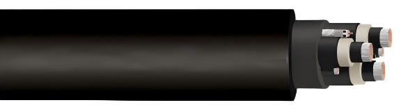
Main Cores and the Triple-Layer Insulation System
The three main power cores at 185 mm² cross-section are the primary current-carrying elements. Each conductor uses finely stranded tinned copper wire classified as IEC 60228 Class 5. The tinning serves a dual purpose: it prevents oxidative corrosion of the copper surface in a salt-laden marine environment, and it ensures reliable contact quality at terminations even after years of cyclic mechanical loading.
The insulation applied to each main core is not a single-material extrusion but a precisely engineered triple-layer co-extruded system, and this is the technical heart of the cable's high-voltage performance.
The innermost layer is a semi-conductive stress control layer applied directly over the stranded conductor. It smooths the irregular surface geometry created by individual wire strands. Without it, the electric field at the insulation-conductor interface would be distorted by strand-tip concentrations — a known initiation site for partial discharge and eventual insulation treeing failure. The semi-conductive layer creates a geometrically uniform interface, distributing the electric field evenly before it enters the main insulation.
The middle layer is EPR main insulation conforming to IEC 60092-360. Ethylene Propylene Rubber is the material of choice for marine and dynamic-service high-voltage cables for reasons that XLPE simply cannot match in reeling applications. EPR retains its mechanical flexibility down to –30°C under bending loads, while maintaining rated electrical performance at 90°C continuous conductor temperature. Its molecular structure resists ozone degradation, moisture absorption, and the mechanical fatigue associated with repeated bending — making it inherently suited for cyclic service in a way that semicrystalline XLPE is not.
The outermost insulation layer is an outer semi-conductive insulation shield layer, co-extruded simultaneously with the EPR main insulation. Working in conjunction with the metallic screen, it confines the high-voltage electric field entirely within the insulation system, preventing inductive coupling to surrounding conductors and eliminating the risk of external surface tracking. Critically, because all three layers are co-extruded in a single pass, there are no micro-gaps at the layer interfaces — and inter-layer air voids are the primary initiation site for partial discharge in sequentially extruded insulation systems. This co-extrusion integrity is the defining quality differentiator between premium and standard marine high-voltage cables.
Ground Conductor
An independent ground conductor at 95 mm² cross-section — also finely stranded tinned copper with a semi-conductive layer — provides a dedicated, low-impedance fault current path. IEC/ISO/IEEE 80005-1 mandates independent ground continuity as a system-level safety requirement, ensuring that in the event of an insulation fault on any phase, fault current flows through the ground conductor rather than through personnel, equipment frames, or the seawater-connected vessel hull.
Pilot Cores: The Control Nervous System
Eight individually screened pilot cores at 2.5 mm² cross-section — white insulation with black numerals 1 through 8 for unambiguous field identification — carry the low-voltage control and interlock signals that make automated shore connection possible. These cores transmit the interlock chain between quayside equipment and shipboard systems, enabling the protection logic that prevents cable energization before plug insertion is confirmed and de-energizes the cable before disconnection begins. EPR insulation on the pilot cores ensures they exhibit the same thermal and mechanical characteristics as the main insulation system, maintaining signal integrity under bending and temperature extremes.
Integrated Optical Fiber Element
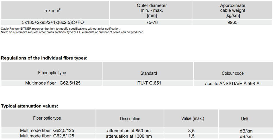
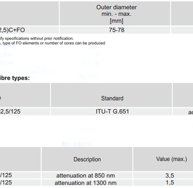
Twelve multimode optical fibers in G62.5/125 OM1 configuration per IEC 60793-2-10 are integrated into the cable assembly, with maximum attenuation values of 3.5 dB/km at 850 nm and 1.5 dB/km at 1300 nm. This embedded fiber link allows the shore power management system to transmit diagnostic data, remote control signals, and real-time fault telemetry through the cable itself — eliminating the need for a parallel communication cable run along the quayside and resulting in a simpler, more reliable system architecture with fewer connection points.
Core Arrangement and Double-Layer Sheath
The three main power cores are laid around a central support element, with the ground conductor, screened pilot core bundle, and optical fiber element occupying the interstitial spaces. This geometry achieves a highly circular cross-section — critical for uniform compression and stress distribution during reeling — resulting in an outer diameter of 75 to 78 mm and a cable mass of approximately 9,965 kg/km.
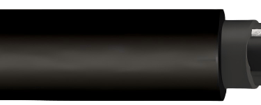
The sheath system consists of two distinct layers. An inner thermoplastic sheath buffers the mechanical loads transmitted during reeling, acting as a compliant interface between the core assembly and the outer protection. The outer sheath is thermoplastic polyurethane conforming to EN 50363-10-2. TPU was selected over PVC and standard polyethylene compounds for its exceptional wear resistance, high tensile strength, and tear propagation resistance — properties that directly determine how long the cable survives the abrasive contact conditions of drum flanges, sheave wheels, and quayside surfaces.


Thermal and Mechanical Parameters: Boundaries Defined by Engineering Judgment
Thermal Parameters
The cable is rated for an ambient temperature range of –40°C to +90°C in fixed installation, narrowing to –30°C to +90°C for reeling operation. The distinction is deliberate. While the EPR insulation and TPU sheath can withstand static cold exposure down to –40°C, the act of bending a large-diameter cable at temperatures below –30°C generates localized tensile strain at the outer sheath surface that could initiate micro-cracking in any elastomeric material. Setting the reeling lower bound at –30°C reflects actual material behavior under combined thermal and mechanical loading, not a simple material datasheet minimum.
The maximum permissible continuous conductor temperature is 90°C, consistent with EPR-class insulation. Short-circuit events are covered by a maximum conductor temperature of 200°C, providing substantial thermal headroom above the continuous rating to accommodate fault clearing without insulation degradation.
Mechanical Parameters
The maximum tensile load of 25 N/mm² per conductor translates to a permitted pulling force of approximately 4,625 N on the 185 mm² main cores. This value must encompass not only the static hanging weight of the cable span between ship and quay, but also the dynamic inertial loads generated during vessel motion and reeling acceleration. System designers must account for both components when sizing cable support and tensioning arrangements.
Bending radius limits are defined across three service categories following DIN VDE 0298-3. Fixed installation requires a minimum bend radius of 6× the cable outer diameter. Free movement, where the cable undergoes occasional repositioning without cyclic bending, requires 10× the outer diameter. Reeling applications require 12× the cable outer diameter — approximately 900 to 940 mm — which directly defines the minimum permissible reel drum hub radius in any compliant installation. These limits represent the boundary below which cumulative fatigue damage to conductors and insulation progresses at an unacceptable rate.
Electrical Performance: Headroom at Every Level
The cable carries a rated voltage U₀/U of 6/10 kV, with maximum permissible operating voltages of 6.9/12 kV in AC systems and 9/18 kV in DC systems. The AC withstand test voltage is 21 kV — 3.5 times the U₀ value. This substantial test margin reflects the insulation qualification philosophy of IEC/ISO/IEEE 80005-1, where cables must demonstrate voltage withstand capability well beyond operational extremes to account for the cumulative dielectric degradation expected across a dynamic, outdoor marine service life.
Conductor DC resistance values at 20°C are defined for all conductor sizes. The 185 mm² main cores exhibit a maximum resistance of 0.108 Ω/km, the 95 mm² ground conductor reaches a maximum of 0.210 Ω/km, and the 2.5 mm² pilot cores are rated at a maximum of 8.21 Ω/km. Current-carrying capacities are determined in accordance with DIN VDE 0298-4, which accounts for the specific installation geometry of reeling cable systems rather than applying bundled-cable correction factors typical of fixed installations.
For engineers calculating voltage drop across a typical 50-meter shore connection span, the 0.108 Ω/km resistance of the 185 mm² phase conductors yields a per-phase circuit resistance of just 5.4 mΩ — a value that confirms the cable's suitability for full-power supply of the largest cruise vessels currently in service.
Chemical and Environmental Resistance: Built for the Port Environment
Halogen-Free Flame Retardancy
The entire cable assembly — insulation, fillers, inner sheath, and outer TPU jacket — is halogen-free, verified against EN 60754 and compliant with both RoHS 2015/863/EU and CPR 305/2011. Flame retardancy is tested to DIN EN/IEC 60332-1-2. The practical significance of the halogen-free specification becomes apparent under fire conditions: conventional PVC-insulated cables release hydrogen chloride gas when burning, which combines with atmospheric moisture to form hydrochloric acid. In enclosed quayside equipment rooms or ship interiors, this corrosive smoke damages sensitive electronics and control equipment, complicates firefighting, and poses acute toxicity risks to personnel. The halogen-free formulation eliminates this secondary damage mechanism entirely.
Oil Resistance and Chemical Compatibility
The outer TPU sheath meets the oil resistance requirements of DIN EN/IEC 60811-404 — a critical property for any cable deployed in harbor environments where incidental contact with hydraulic fluid, diesel fuel, and lubricating grease is routine. Swelling or softening of the sheath under hydrocarbon exposure would accelerate mechanical wear and compromise the sheath's protective function. The TPU compound's resistance to a broad range of industrial chemicals ensures that contamination events do not trigger progressive sheath degradation.
Weather and Water Resistance
The cable is rated for unrestricted indoor and outdoor use with demonstrated resistance to ozone, UV radiation, and sustained moisture exposure. The outdoor rating is particularly relevant given that reeling cables spend much of their service life exposed on drum assemblies mounted on cranes or in open deck areas, cycling through daily UV and temperature variations across many years of service.
The most demanding environmental certification is the cable's water resistance rating to protection class AD8, meaning the cable can operate continuously when completely submerged under water pressure up to 10 bar — equivalent to a water column of approximately 100 meters. In practical terms, this covers any scenario encountered at a harbor quay: cable sections temporarily submerged during wave action, tidal flooding events, or operations where the cable pendant momentarily falls into the water. The AD8 rating ensures that water ingress does not trigger insulation failure or ground fault events that would require emergency shutdown of the shore power system.
Crane Types and Motion Modes: Matching the Cable to Deployment Reality
Understanding the Three Motion Regimes
Shore power reeling cables experience fundamentally different mechanical stress profiles depending on the carrier system they serve. Pure reeling motion — periodic winding and unwinding around a drum — is the primary fatigue mechanism. Each cycle subjects the outer cable surface to tensile strain while the inner surface experiences compressive stress. After hundreds of thousands of cycles, cumulative fatigue damage in conductors and insulation accumulates until electrical performance degrades. The 12× outer diameter bending radius requirement limits the maximum strain per cycle to a value that the finely stranded conductors and EPR insulation can sustain without progressive damage accumulation.
Free-hanging catenary motion occurs when the cable spans between the reel outlet and the ship's cable box, moving slowly with tidal height changes and vessel loading variations. This is large-radius, low-frequency bending — far less damaging than drum bending, but it imposes sustained tensile loads that must remain within the cable's rated capacity. Incidental contact and abrasion against structural elements — crane booms, sheave housings, reel flanges — determine sheath wear rate over service life and are the primary driver for selecting TPU over conventional jacket materials.
Container Terminal Shore Power Cranes
On quay cranes serving container vessels, the shore power reel is typically mounted on the crane travel structure. As the crane traverses along the quay to service different vessel bays, the cable unreels from a drum and trails behind, accumulating lateral bending loads in addition to the primary reeling motion. The cable must maintain a circular cross-section under these combined loading conditions — ovalization during reeling would shift internal component positions and create localized stress concentrations that accelerate fatigue failure. The central support element and tightly arranged core geometry resist ovalization under bending, preserving the circular form that ensures uniform drum winding layer after layer.
Mobile Shore Power Carrier Systems
Mobile carrier platforms — self-propelled or track-guided vehicles that bring the shore connection point to wherever the vessel's cable box is located — require cables that can accommodate multi-directional bending during positioning maneuvers. Unlike a fixed crane with a single travel axis, a mobile carrier may turn, reverse, and articulate in ways that impose asymmetric bending loads not aligned with the drum winding axis. The high flexibility of the Class 5 stranded conductors and the dimensional stability of the cable cross-section under off-axis loading are critical performance requirements in this application.
Cruise Liner Shore Power Systems
Cruise vessels present a combination of high power demand and extended berth times during which the cable must maintain reliable connectivity through tidal excursions of several meters. The large conductor cross-sections accommodate the high load currents, while the integrated pilot cores and optical fiber channel enable the complex interlock and communication logic required between ship and shore under IEC/ISO/IEEE 80005-1 compliant systems. The single-operator automated connection capability enabled by this integrated cable design is particularly valuable in cruise terminal operations where port call efficiency is a primary economic driver.
Against Standard High-Voltage Cables: What the Difference Actually Means
The specification gap between a purpose-built HVSC reeling cable and a standard terrestrial high-voltage cable is not one of degree but of category. Each domain where they diverge reflects a specific engineering decision made in response to a specific failure mode or operational requirement.
Standard land high-voltage cables use XLPE insulation — a semicrystalline polymer that becomes progressively stiffer at low temperatures and is susceptible to micro-cracking at bending points under repeated flexure. Their outer jackets are typically PVC or standard polyethylene, which offer adequate protection for buried or trunked fixed installations but wear rapidly under the drum contact conditions of a reeling system. They carry no pilot cores, no optical fiber, and no provisions for the interlock signaling that IEC/ISO/IEEE 80005-1 requires. Their water ingress protection typically reaches IP55 at best — nowhere near the AD8 sustained submersion rating required for quayside cable deployment. And critically, they carry no DNV certification and no IEC 80005-1 compliance documentation, meaning their use in a certified HVSC installation would require either full reclassification testing or a system-level deviation approval — both costly and time-consuming.
The practical consequence of using a non-specialist cable in a reeling shore power application is not gradual performance decline — it is premature failure at an unpredictable point in the installation's service life. XLPE insulation subjected to repeated bending below its glass transition temperature will develop micro-cracks at the semi-conductor interface. PVC sheaths subjected to continuous drum contact abrasion will wear through to the core assembly within a fraction of the expected service life. Neither failure mode is recoverable without full cable replacement, and either can force an unplanned shore power outage during a vessel's port call — with all the operational and commercial consequences that entails.
Engineering Value: Lifetime, Reliability, and Safety as System Properties
Service Life and Fatigue Management
The primary determinant of reeling cable service life is the accumulated bending fatigue cycle count before conductor wire breakage or insulation degradation reaches a threshold that affects electrical performance. IEC 60228 Class 5 conductors use more strands of finer wire than standard Class 2 conductors. For a given conductor bending radius, finer individual wire diameter means lower bending strain per wire per cycle — and fatigue damage accumulates as a function of strain amplitude raised to a high power depending on material. Halving the wire diameter can therefore increase cycle life by an order of magnitude or more, which is why highly stranded conductors are non-negotiable for reeling cable design.
EPR insulation's elastic recovery after bending means the insulation does not retain permanent deformation at bending points, unlike semicrystalline polymers that exhibit localized yielding under repeated flexure. The TPU outer sheath provides documented abrasion life several times longer than standard PVC compounds in standardized wear testing, translating directly into extended intervals before sheath inspection or replacement actions are required. The 24-month product warranty reflects confidence in the cable's performance under the specific conditions for which it was engineered.
System Reliability and Designed-In Redundancy
Reliability in a shore power cable system is an emergent property of system architecture, not an intrinsic property of any single component. The triple-layer co-extruded insulation provides layered protection: a single interface defect in the inner or outer semi-conductive layer does not immediately create a path to electrical failure because the EPR main insulation layer remains intact. The independent screened ground conductor, combined with the pilot core interlock logic, enables fault detection at levels far below those that would cause equipment damage or personnel hazard. The integrated optical fiber channel allows continuous remote monitoring of system parameters, converting the cable from a passive conductor into an active element of the HVSC management system — enabling predictive maintenance that replaces unplanned outage events with scheduled inspection intervals.
Safety: From Material Chemistry to System Certification
Safety in a shore power installation spans material chemistry, mechanical integrity, electrical protection, and regulatory compliance simultaneously. At the material level, the halogen-free formulation eliminates the toxic combustion products that would otherwise compromise personnel safety and equipment survivability during a fire event. The AD8 water resistance rating closes the failure pathway of seawater ingress to a live conductor — a scenario that would otherwise create a ground fault with potentially fatal consequences for anyone in contact with the vessel hull or surrounding dock water.
At the system level, DNV certification means the cable has been subjected to independent third-party evaluation of its construction, material characteristics, and electrical performance against the requirements of the applicable classification society rules. This is not a self-declaration — it represents a documented audit trail that satisfies the approval requirements of virtually all major port authorities and ship operators running certified HVSC installations. Compliance with CPR 305/2011 additionally provides the regulatory framework for deployment in EU-regulated port infrastructure projects.
The total cost of ownership calculation for a shore power cable installation must account not only for the purchase price difference between a specialist and a general-purpose cable, but for the cost of an unplanned shore power outage during a cruise vessel's turnaround, the labor cost of a mid-season cable replacement, and the reputational cost of a safety incident traced to a specification shortcut. Viewed across a realistic 15 to 20-year system service life, the engineering and commercial case for the purpose-built solution is unambiguous.
Conclusion
The (N)TSCGEW11Y 6/10 kV represents the current state of the art in HVSC cable engineering. It brings together high-voltage insulation reliability, dynamic fatigue resistance, halogen-free environmental compliance, and multi-function integration — power, ground, control, and data — within a single reelable assembly that a single operator can connect to any vessel type at berth.
Shore power works when every component in the chain is engineered for exactly the conditions it will face. For the cable that connects ship to shore, those conditions are among the most mechanically and environmentally demanding in the entire field of power cable engineering. Selecting a cable designed specifically for that purpose is not over-specification — it is the correct specification.
Port crane cables | Mining cables | Reeling cables | Trailing cables | Festoon cables | Heavy-duty power cables | Medium voltage cables | Offshore crane cables | Underground mining cables | Dragline cables | Shearer cables | Container handling cables | STS crane cables | RTG cables | Mobile equipment cables | Armored cables | Flexible power cables | VFD cables | Submersible cables | Cold resistant cables | Abrasion resistant cables | Flame retardant cables | Marine environment cables | Opencast mining | Underground operations
© 2006 All rights reserved.
[INDUSTRIAL_CABLES]
INDUSTRIAL GRADE CABLE SYSTEMS | PORT & MINING SOLUTIONS
TEL: +86 153 7530 2641 |MAIL: hongjing.Wang@feichuncables.com