(N)TSCGEWOEU Medium-Voltage Reeling Cable: The Complete Engineering Guide for Ports, Cranes, and Heavy Marine Equipment
A complete technical guide to (N)TSCGEWOEU medium-voltage reeling cable: construction, semiconductive field control, voltage classes, torsion and high-speed reeling performance, environmental resistance, and selection tips for demanding port and marine crane applications.
hongjing.Wang@Feichun
6/24/202622 min read
Introduction
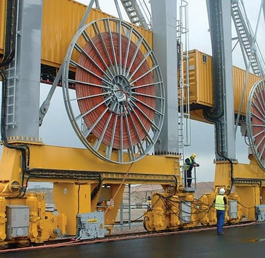
Walk along the quay of any major container terminal in the Gulf, the Red Sea, or the Mediterranean coast, and you will see enormous machines in constant motion. Ship-to-shore cranes glide along the waterfront at high speed, lifting forty-tonne containers off vessels and setting them down with precision. Yard cranes shuttle endlessly between stacks. Every one of these machines must be fed electrical power while it moves, and at the scale and speed of modern automated terminals, that power is increasingly delivered not at low voltage but at medium voltage.
The (N)TSCGEWOEU cable is engineered precisely for this duty. It is a flexible medium-voltage reeling cable built to supply power to mobile equipment operating under high to extreme mechanical stress, the combination of high travel speeds, dynamic tensile loads, repeated changes of direction across different planes, churning over guide rollers, and continuous torsional stress that characterizes fast-moving crane systems. Where a low-voltage reeling cable handles smaller machines, this cable serves the most demanding, highest-power, fastest-moving equipment in the modern port and industrial landscape.
For engineers, terminal operators, and procurement specialists across the Middle East, the choice of a medium-voltage reeling cable is among the most consequential technical decisions in a crane electrification project. These cables operate in some of the harshest conditions on earth: relentless sun and UV, salt-laden coastal humidity, abrasive dust, oil and chemical exposure, extreme summer heat, and the unending mechanical punishment of high-speed reeling. A cable that fails in this environment does not merely need replacing; it shuts down a crane, halts a vessel's loading operation, and costs the terminal enormous sums in lost throughput. The right cable, by contrast, runs reliably for years under conditions that would destroy ordinary cable in weeks.
This comprehensive guide explains what the (N)TSCGEWOEU cable is, what its designation means, how it is constructed layer by layer, how it performs electrically and mechanically, how it resists the environmental assaults of marine and desert conditions, where it is used, why it is chosen for severe-duty applications, and how to select the correct version for a specific system. Whether you are electrifying a new automated terminal or upgrading the reeling cable on an existing high-speed STS crane, this article gives you the technical foundation to specify with confidence.
Why Port and Marine Equipment Needs Special Reeling Cables
It is worth establishing at the outset why a special cable is needed at all. In a fixed electrical installation, a power cable is bolted in place and never moves. Its enemies are time, heat, and electrical stress, all of which are well understood and easy to design around. A reeling cable lives in a completely different reality. It is a moving, working part of the machine. Every time the crane travels, the cable reel rotates, pulling cable off the drum or winding it back on. The cable bends sharply around the reel core, twists along its length, drags across deflection rollers, accelerates and decelerates, and absorbs dynamic tensile loads, all while carrying medium-voltage power and being exposed continuously to sun, salt, and abrasion. This cycle repeats thousands of times every day for years.
A standard medium-voltage power cable placed in this role would fail almost immediately. Its rigid conductors would fatigue and crack, its insulation would split, and its sheath would abrade through. The (N)TSCGEWOEU is a fundamentally different class of product, engineered from the conductor strands outward to survive continuous, high-speed motion at medium voltage.
How It Differs From Standard Power Cables
Three differences stand out. First, flexibility: every layer, from the very finely stranded conductors to the rubber insulation and sheathing, is designed to bend and move without fatiguing. Second, mechanical reinforcement: a vulcanized anti-torsion braid carries the tensile and torsional loads so the conductors are protected. Third, electrical field control at medium voltage: unlike a low-voltage cable, a medium-voltage design requires semiconductive layers to manage the electrical field around the conductors, a critical feature we will explore in detail. Together, these differences make the cable a purpose-built solution for high-power mobile equipment rather than an adapted version of a static cable.
Meaning of the Cable Code: Decoding (N)TSCGEWOEU
One of the most valuable skills an engineer can develop is the ability to read a cable's type designation. These codes follow harmonized German and international (VDE/DIN) conventions, and each letter carries specific meaning about construction, materials, and intended use. Understanding the logic lets you identify a cable's function at a glance, compare offerings from different suppliers, and avoid costly specification mistakes. Let us decode this designation.
(N) — The "N" indicates conformity to the relevant harmonized VDE/DIN standard framework. The parentheses signal that the cable is based on, and broadly aligned with, the recognized national and European specification system for rubber-insulated flexible cables, here specifically the standard governing medium-voltage reeling cables (based on DIN VDE 0250-813).
T — This designates the load-bearing, tension-carrying construction element. In a reeling cable, the structure must absorb the pulling forces applied as cable is wound off and onto the drum, and this letter reflects that tension-bearing capability.
SC — This points to the screened, semiconductive construction that is essential in medium-voltage cables. The "S" relates to the screening and the "C" to the conductive (semiconductive) field-control layers. At medium voltage, you cannot simply place insulation over a conductor; you must control the electrical field with semiconductive layers, and this part of the code reflects that.
G — This denotes the rubber-based (elastomer) insulation and compound system. Rubber compounds, particularly EPR-based insulation, give the cable its flexibility across a wide temperature range together with strong electrical and weathering performance.
E — This relates to the earth/ground conductor arrangement integrated into the construction. In this cable, the protective earth conductor is split into multiple parts and positioned in the gaps between the main cores, a sophisticated design we will examine shortly.
W — This indicates the reinforced, weather-resistant heavy-duty construction suited to outdoor and mobile use, the toughness that lets the cable survive abrasion, churning over rollers, and environmental exposure.
OE — This refers to the elastomer (rubber) outer sheathing system based on heavy-duty compounds. The outer sheath is what protects the entire cable from the outside world, and a chloroprene-type (PCP) rubber compound provides the necessary abrasion and tear resistance.
U — This denotes suitability for reeling, the construction features that allow repeated winding and unwinding without damage.
Put together, the designation describes a standards-based, tension-bearing, screened and semiconductively field-controlled, rubber-insulated, earthed, weather-resistant, rubber-sheathed reeling cable for medium-voltage mobile equipment. That is a remarkable density of engineering information in a single code.
Why the Designation Matters for Engineers and Buyers
Specification errors in medium-voltage cable are expensive and dangerous. A procurement manager who understands the code will not accidentally order a low-voltage cable for a medium-voltage circuit, or a fixed-installation cable for a reeling application. An engineer who recognizes the screened, semiconductive medium-voltage construction will understand that this cable requires proper field control and cannot be substituted with a cheaper unscreened design. The designation is a precise technical language, and fluency in it prevents the kind of mismatches that lead to insulation failures, safety incidents, and unplanned downtime. In medium-voltage systems, where the electrical stresses are far higher than at low voltage, getting the specification right is not optional, it is a matter of both reliability and safety.
Relationship to Medium-Voltage Reeling Cable Families
This cable belongs to the family of medium-voltage reeling cables that sit above low-voltage crane cables in electrical duty. While a low-voltage reeling cable might be rated at 0.6/1 kV, this medium-voltage family spans a range of much higher voltage classes, making it suitable for the high-power demands of large, fast, modern crane systems. It represents the premium tier of reeling cable, where electrical capacity and mechanical endurance are both pushed to their highest levels.
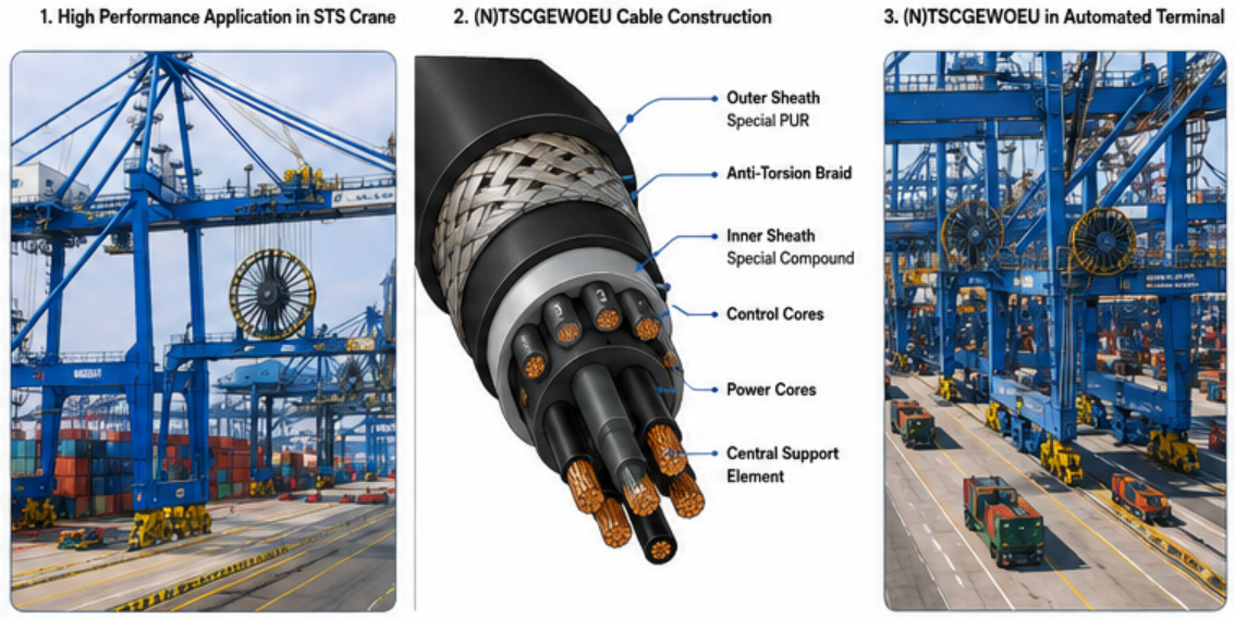
Cable Construction: How the (N)TSCGEWOEU Is Built
The performance of any reeling cable flows directly from its construction, and in a medium-voltage design every layer must serve both an electrical and a mechanical purpose simultaneously. Let us walk through the construction from the conductor outward, examining what each element does and why it matters.
Flexible Tinned Copper Conductors
At the core are the current-carrying conductors, made of electrolytic copper, tinned, and very finely stranded to the flexibility class (class FS, the very fine stranding class per DIN VDE 0295). This very fine stranding is the foundation of the cable's flexibility and fatigue resistance.
A rigid or coarsely stranded conductor work-hardens and cracks when bent repeatedly. A conductor built from many extremely fine copper strands behaves completely differently: the fine wires slide and flex relative to one another, distributing bending stress across hundreds of tiny filaments rather than concentrating it. This dramatically extends fatigue life, which is exactly what a cable that bends millions of times must have.
The tinning, a thin protective layer of tin over each copper strand, serves two important functions. It protects the copper from corrosion and oxidation, a major advantage in the salt-laden, humid air of coastal port environments throughout the Middle East, where bare copper would corrode over time. And it improves long-term contact reliability at terminations. Both the main conductors and the earth conductor use this same high-quality tinned, finely stranded copper construction.
Rubber Insulation (High-Grade EPR)
Each conductor is insulated with a high-grade special compound based on high-quality EPR (ethylene propylene rubber, at least quality 3GI3 per the relevant VDE standard), engineered for improved mechanical and electrical characteristics. EPR is the premier insulation material for flexible and reeling cables. It remains pliable across a very wide temperature range, withstands high operating temperatures, resists moisture and partial discharge, and offers excellent ozone and weathering resistance. Crucially for a medium-voltage cable, EPR provides the dielectric strength and stability needed to insulate higher voltages reliably while still bending and flexing through countless cycles.
Semiconductive Layers: Electrical Field Control
Here is the feature that fundamentally distinguishes a medium-voltage cable from a low-voltage one: the electrical field control system built from semiconductive layers. The construction includes an inner semiconductive layer of EPR directly over the conductor and an outer semiconductive layer of modified NBR (nitrile rubber) over the insulation.
Why is this necessary? At medium voltage, the electrical field around a conductor becomes intense. Without field control, the field would concentrate unevenly at the surface of the conductor and at any small imperfection, creating high-stress points where partial discharge and insulation breakdown can begin. The inner semiconductive layer smooths the field at the conductor surface, eliminating these stress concentrations. The outer semiconductive layer does the same at the outer surface of the insulation, ensuring a uniform, controlled field across the full insulation thickness. Together they make the medium-voltage insulation reliable and long-lived.
A particularly valuable practical feature here is that the outer semiconductive layer is designed to be stripped when cold, an "easy strip" design that makes the cable far simpler and faster to terminate in the field. For maintenance teams working in hot, demanding port conditions, a cable that can be prepared quickly and cleanly is a meaningful operational advantage, reducing the time a crane is out of service during a cable change. The cores themselves are identified by natural-coloured insulation with a black semiconductive layer.
Grounding Conductor Design: The Split Earth
The earth conductor in this cable uses a sophisticated arrangement. Rather than a single bulky ground core, the construction uses a three-core design with the earth conductor split into three parts, positioned in the interstices, the gaps between the three main power cores.
This split-earth design is clever for several reasons. By distributing the protective earth conductor symmetrically into the spaces between the main cores, the design keeps the cable's cross-section compact, round, and dimensionally stable. It maintains the electrical symmetry of the three-phase system, which contributes to the cable's very low electromagnetic interference level. And it ensures the protective earthing path is robust and well-integrated into the structure rather than being a vulnerable separate element. For a power cable, the integrity of this earthing path is essential to safety, providing the route for fault current to flow safely and trip protective devices, protecting both equipment and the personnel working around these high-power machines.
The Sheath System: A Sandwich of Strength
The sheath system is where mechanical durability is engineered, and it uses a sophisticated multi-layer "sandwich" construction:
A double-layer inner sheath based on EPR (quality at least 5GM3) sits over the cores, coloured red and serving additionally as a water barrier. This inner sheath stabilizes the core bundle and provides the first line of moisture defense.
Above it sits the anti-torsion braid, a reinforced braid made of polyester threads embedded in a vulcanized bond between the inner and outer sheaths. This is the cable's mechanical backbone. When the reel pulls the cable, this braid carries the tensile load so the copper conductors are not stretched. When the cable twists, the braid resists and controls the torsional movement so the internal cores are not torn apart. Because it is vulcanized into a single bonded structure with the surrounding rubber, the inner sheath, reinforcement braid, and outer sheath behave as one unified body rather than as separate sliding layers. This bonded construction is precisely what allows the cable to survive simultaneous pulling and twisting, the exact combination of forces that defines high-speed reeling service.
Finally, a double-layer outer sheath based on heavy-duty PCP (polychloroprene, a chloroprene rubber compound, quality at least 5GM5) forms the outermost layer, coloured bright red. This sandwich-structured outer sheath achieves a deliberate combination of flexibility and robustness: it is abrasion-proof and tear-proof, standing up to the relentless churning over rollers, dragging across guides, and impacts of reeling service, while remaining flexible enough not to fight the reel. Chloroprene rubber is particularly valued for its outstanding resistance to oil, abrasion, weather, ozone, and flame, making it an ideal outer-jacket material for harsh marine and industrial environments.
Construction Summary
Read as a whole, the construction is a deliberately engineered electromechanical system:
Very finely stranded tinned copper conductors for flexibility, fatigue resistance, and corrosion protection.
High-grade EPR insulation for dielectric strength and flexibility across a wide temperature range.
Inner and outer semiconductive layers for medium-voltage electrical field control, with an easy-strip outer layer for fast termination.
Split three-part earth conductor in the interstices for compactness, symmetry, low interference, and grounding safety.
Double-layer EPR inner sheath serving as bedding and water barrier.
Vulcanized polyester anti-torsion braid for tensile and torsional strength.
Double-layer chloroprene (PCP) outer sheath for abrasion, tear, oil, and weather resistance.
Every layer answers the central challenge: deliver medium-voltage power reliably through a cable that never stops moving, in one of the harshest environments on earth.
Electrical Performance: Rated for High-Power Crane Supply
A medium-voltage reeling cable must deliver substantial power safely and reliably while in continuous motion. Here are the key electrical parameters and why each one matters.
Available Voltage Ratings
This cable family spans a broad range of medium-voltage classes, allowing it to be matched to the specific voltage of a given crane or terminal system. The available rated voltages (U₀/U) include classes such as 1.8/3 kV, 3.6/6 kV, 6/10 kV, 8.7/15 kV, and 12/20 kV, with corresponding maximum permissible operating voltages and test voltages scaled to each class. For example, at the 1.8/3 kV class, the cable carries a maximum permissible AC operating voltage of 2.1/3.6 kV, a maximum permissible DC operating voltage of 2.7/5.4 kV, and withstands an AC test voltage of 6 kV. Higher voltage classes carry correspondingly higher test voltages, rising up to the order of 29 kV for the highest class.
This range is important because it lets the engineer select exactly the voltage capability the system requires, from moderate medium-voltage feeds up to the higher classes needed for the largest, most power-hungry cranes. Each class is built with insulation thickness and field control appropriate to its voltage.
Why Medium-Voltage Capability Is Important
The shift to medium voltage in crane power supply reflects a simple engineering reality: as cranes get larger, faster, and more powerful, the current required to deliver that power at low voltage becomes impractically high. Higher current means larger, heavier, more expensive conductors and greater losses. By supplying power at medium voltage, the same amount of power can be delivered at much lower current, allowing smaller conductors, lower losses, and longer feasible cable runs. For the high-speed ship-to-shore cranes and long-travel systems of modern automated terminals, medium-voltage supply is often the only practical way to deliver the required power over the necessary distances. This cable makes that possible while retaining the flexibility and durability of a reeling cable.
Test Voltage and Insulation Integrity
Each voltage class is subjected to an AC test voltage well above its rated working voltage, confirming the integrity of the insulation and the field-control system. This routine high-voltage testing ensures that every length of cable can withstand voltages substantially higher than it will ever see in normal service, providing a safety margin against transient overvoltages and confirming that the insulation is free of defects. Combined with the semiconductive field-control layers, this delivers reliable, long-lived medium-voltage insulation performance.
Current-Carrying Capacity and Low Interference
The cable's current-carrying capacity is determined according to the relevant VDE standard (DIN VDE 0298, Part 4), with the nominal values based on rubber cables laid on a surface at a 30 °C ambient reference temperature. Higher values may be permissible in specific cases in consultation with the manufacturer. As a practical example of capacity, the larger cross-sections in the range carry several hundred amperes per phase, with the largest conductors capable of well over 600 amperes depending on voltage class and installation conditions.
A further electrical advantage is the cable's extremely low electromagnetic interference level, achieved through the symmetrical three-core design manufactured to very narrow tolerances. Low interference is increasingly valuable in automated terminals packed with sensitive control electronics, sensors, and communication systems, where electromagnetic noise from power cables can disrupt operations. Where data transmission is required, special designs incorporating twisted shielded pairs or individually screened control elements are available, and fibre-optic-integrated variants exist within the broader product family.
A Note on De-Rating
As with any cable, the tabulated current-carrying capacity assumes reference conditions. In real Middle Eastern installations, high ambient temperatures, direct solar heating, and the heat-retaining effect of cable wound in layers on a reel all reduce the usable current. A competent engineer always applies the appropriate thermal and reeling de-rating factors when sizing the conductor, ensuring the chosen cross-section carries the actual load under worst-case conditions rather than under idealized laboratory conditions. In a region where ambient temperatures and solar loading are extreme, this discipline is essential to avoiding overheating and premature failure.
Mechanical Performance: Engineered for Extreme Motion
If the electrical parameters confirm the cable can carry the power, the mechanical parameters confirm it can survive the punishment, and this is where the (N)TSCGEWOEU truly distinguishes itself. The central design challenge of any high-speed reeling cable is mechanical: how do you build a cable that endures continuous, fast, multi-directional motion at medium voltage without fatiguing and breaking?
Anti-Torsion Construction
The cable is rated to withstand torsional stress of ± 25 degrees per meter. Torsion, the twisting of the cable along its length, is one of the most destructive forces a reeling cable faces, especially in drum and spiral reeling systems where the cable is twisted as it winds. The ± 25 °/m rating quantifies how much twist per meter of length the construction can repeatedly endure. This capability comes directly from the vulcanized polyester anti-torsion braid, which controls and resists twisting so the internal conductors and field-control layers are protected. The design is verified by dedicated torsional stress testing, confirming its endurance under exactly the twisting conditions it will face in service.
High Flexibility and Tensile Strength
The cable is engineered to carry significant tensile loads while protecting the conductors. The maximum tensile load on the conductor is rated at 20 N/mm² in normal service, rising to up to 30 N/mm² during acceleration (with the standard reference value per DIN VDE 0298 Part 3 being 15 N/mm²). The acceleration figure matters because it is during the rapid acceleration of a fast-moving crane that the cable experiences its highest dynamic pulling forces. The high-strength, vulcanized sheath system carries these loads so the very finely stranded conductors are not stretched or damaged.
In practical terms, the larger cross-sections in the range carry permissible static tensile forces in the range of many thousands of newtons, with dynamic tensile forces during acceleration rated even higher, reflecting the substantial pulling forces these cables routinely absorb on large, fast cranes.
Bending Radius and Travel Speed
Bending performance is defined according to the relevant VDE standard (DIN VDE 0298 Part 3), with specific minimum free-moving bending radii published for each cross-section. For reverse, S-type directional changes, where the cable bends one way then the other, the construction requires a minimum spacing of 20 times the cable diameter (20 × D), reflecting the extra stress that reversing bends impose. Respecting these bending radii at every point in the reeling system, the reel core, the deflection rollers, and the guide sheaves, is essential to achieving long cable life.
The cable's travel-speed capability is genuinely impressive. In gantry reeling operation, there is effectively no speed restriction, with the manufacturer recommending consultation only for speeds beyond 240 m/min. This is an extraordinarily high reeling speed, double or more the speed of many low-voltage reeling cables, and it is exactly what the fastest modern container cranes require. The ability to reel at such high speeds without damage is one of the defining capabilities of this premium cable class, enabling the high-throughput operation that automated terminals depend on.
Resistance to Repeated Motion and Severe Stress
The cable is specifically designed for application under high to extreme mechanical stress: high travel speeds, dynamic tensile loads, multiple changes of direction into different planes, churning over rollers, and torsional stress, often all at once. To prove its endurance, the design is subjected to additional verification including reversed bending tests and torsional stress tests, confirming that it survives the precise combination of forces it will encounter. This is a cable built not merely to tolerate motion but to thrive under the most severe dynamic duty cycles in the industry.
Temperature Range
The cable operates across a wide ambient temperature range: for fixed installation, from a minimum of -50 °C to a maximum of +80 °C, and in fully flexible (reeling) operation, from -35 °C to +80 °C. The conductor itself is rated for a maximum permissible operating temperature of 90 °C, with a maximum short-circuit temperature at the conductor of 250 °C.
The +80 °C maximum ambient rating is especially relevant for Middle Eastern applications. When peak regional air temperatures combine with intense direct solar heating on equipment surfaces and the self-heating of a loaded cable, the conditions around the cable become extreme. An +80 °C ambient capability provides the margin needed to operate reliably in these conditions. The 90 °C conductor rating provides thermal headroom for heavy motor loads, and the 250 °C short-circuit rating ensures the cable survives fault events long enough for protective devices to clear them, a vital safety margin in medium-voltage systems where fault energies are high.
Environmental Resistance: Built for Marine and Desert Conditions
Few operating environments are as punishing as a Middle Eastern port. The cable must endure intense year-round sun, salt-laden coastal humidity, abrasive airborne dust, oil and chemical contamination, and extreme heat, all simultaneously and continuously. The (N)TSCGEWOEU is engineered to resist every one of these assaults.
UV Resistance
Intense ultraviolet radiation is one of the fastest destroyers of inferior cable jackets. Under sustained UV exposure, poorly formulated sheaths harden, become brittle, crack, and fail. This cable is rated for unrestricted outdoor use with full resistance to UV radiation. The chloroprene-based outer sheath maintains its integrity and flexibility under prolonged solar exposure, a critical factor for achieving long service life in the region's relentless sunshine.
Moisture and Ozone Resistance
The cable offers unrestricted indoor and outdoor use with full resistance to ozone and moisture, and dedicated water resistance per the relevant standard (HD 2216). The double-layer inner sheath additionally serves as a water barrier, providing layered protection against moisture ingress. In humid coastal environments where condensation, rain, and spray are constant, this moisture resistance protects the insulation and field-control system from degradation. Ozone resistance, meanwhile, guards against the gradual cracking that ozone exposure causes in lesser rubber compounds, a particular concern around electrical equipment that can generate ozone.
Oil Resistance
The cable is rated for resistance to oil per the relevant standards (DIN EN 60811-404 and the corresponding VDE specification). Ports and industrial sites are saturated with oils, greases, hydraulic fluids, and fuels, all of which attack and degrade unsuitable cable jackets, causing swelling, softening, and eventual failure. The chloroprene outer sheath's inherent oil resistance ensures the cable maintains its mechanical integrity despite continuous contact with these contaminants.
Marine and Salt-Humidity Suitability
Taken together, these resistances make the cable exceptionally well suited to marine and salt-humidity conditions. The combination of a corrosion-resistant tinned copper conductor, a moisture-barrier inner sheath, water resistance to the relevant standard, and an oil-, UV-, and ozone-resistant chloroprene outer jacket creates a cable that thrives in the coastal port environments where so much of the region's crane infrastructure operates. Salt air, humidity, sun, and oil are not the cable's limits, they are its normal operating environment.
Typical Applications: Where the (N)TSCGEWOEU Belongs
The combination of medium-voltage electrical capacity, extreme mechanical endurance, and comprehensive environmental resistance makes this cable the natural choice for the most demanding mobile-equipment applications. Here are the most relevant use cases, with particular attention to the systems common in Middle Eastern ports and terminals.
Automated Container Terminals
Modern automated container terminals represent the pinnacle of port technology, and they place extraordinary demands on their power cables. Automated cranes operate continuously at high speed with minimal human intervention, cycling their reels relentlessly. The (N)TSCGEWOEU's combination of high-speed reeling capability, medium-voltage power delivery, low electromagnetic interference, and proven durability makes it ideally suited to the automated terminals being built and expanded across the region.
High-Speed Ship-to-Shore (STS) Crane Systems
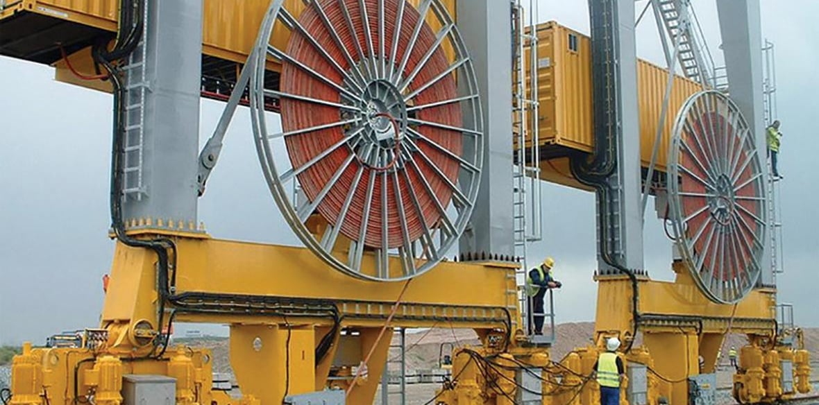
The flagship application is the ship-to-shore container crane, the towering machines that load and unload container vessels at the quayside. These cranes travel along the waterfront at high speed and require substantial power delivered through cable reels. The cable's exceptional travel-speed capability (effectively unrestricted, with consultation recommended only beyond 240 m/min) and its medium-voltage capacity make it specifically suited to feeding these fast, high-power machines.
Continuous-Duty Drum Reeling Power Systems
Any system relying on a motor-driven drum or reel to manage power cable benefits from this cable's anti-torsion construction and high-speed endurance. In continuous-duty reeling systems that wind and unwind cable around the clock, the vulcanized reinforcement and fatigue-resistant conductors deliver the long service life that continuous operation demands.
Long-Travel Crane Equipment
For cranes that travel long distances along the quay or through the yard, the cable's medium-voltage capability is particularly valuable. Delivering power at medium voltage allows longer feasible cable runs with manageable conductor sizes and acceptable losses, making it the practical choice for long-travel installations where low-voltage supply would be impractical.
Heavy Material-Handling and Mining Equipment
Beyond ports, the cable serves heavy material-handling systems and mining equipment operating under severe mechanical stress. Stackers, reclaimers, and other large mobile machines in bulk terminals, stockyards, and mining operations rely on exactly this combination of medium-voltage power, mechanical toughness, and environmental resistance. Wherever large equipment moves under demanding conditions and requires medium-voltage power through a reel, this cable family is the appropriate solution.
Why Choose the (N)TSCGEWOEU
When you weigh the cable's characteristics, a clear set of advantages emerges that make it the right choice for severe-duty medium-voltage reeling applications.
A better fit for severe duty cycles. This cable is purpose-built for high to extreme mechanical stress, the simultaneous combination of high speed, dynamic tension, multi-plane direction changes, churning over rollers, and torsion. Where lesser cables struggle, this design is engineered specifically for the harshest dynamic duty cycles, verified by reversed bending and torsional stress testing.
Suitable for higher power transmission. With voltage classes ranging across the medium-voltage spectrum, the cable delivers the high power that large, fast, modern cranes require, at lower current and with longer feasible runs than low-voltage supply allows. This makes it the enabling technology for high-power crane electrification.
Improved durability in harsh environments. The chloroprene outer sheath, vulcanized reinforcement, moisture-barrier inner sheath, and corrosion-resistant tinned conductors combine to deliver outstanding durability in the marine, humid, hot, oily, dusty conditions of Middle Eastern ports and industrial sites. Resistance to UV, ozone, moisture, and oil is built in, not added on.
Lower risk of premature cable failure. Every element of the design, from the very fine conductor stranding to the easy-strip semiconductive layer to the bonded sandwich sheath, works to extend service life and reduce the risk of unexpected failure. For operators, this translates directly into the outcome that matters most: fewer failures, less downtime, lower lifetime cost, and greater operational reliability. In a terminal where downtime is measured in lost vessel throughput, this reliability is invaluable.
Reliable grounding and low interference. The split-earth design delivers robust protective earthing for safety, while the symmetrical three-core construction provides extremely low electromagnetic interference, protecting the sensitive control and communication systems of automated terminals.
Selection Tips: How to Specify the Right Cable
Choosing the correct medium-voltage reeling cable requires checking several key parameters against the demands of your specific system. Use the following checklist to guide your selection.
1. Check the Voltage Class First
Begin by confirming the system voltage and selecting the matching voltage class, whether 1.8/3 kV, 3.6/6 kV, 6/10 kV, 8.7/15 kV, 12/20 kV, or another class in the range. The cable's rated voltage must meet or exceed the system's operating voltage with appropriate margin. Because the insulation thickness and field control are tailored to each voltage class, this is the foundational selection decision, and getting it right is essential for both safety and reliability in a medium-voltage system.
2. Confirm Drum Speed and Bending Cycles
Match the cable's reeling-speed capability to the travel and reeling speed of your equipment. This cable's effectively unrestricted gantry reeling speed (with consultation recommended beyond 240 m/min) suits even the fastest cranes, but you should always confirm that your system's maximum speed falls within the rated capability. Consider too the frequency and severity of the bending cycles your reeling system imposes, as these determine the fatigue demands on the cable.
3. Verify Torsion and Travel Requirements
Assess the torsional stress your reeling system imposes and confirm it falls within the cable's ± 25 °/m rating. Spiral and drum reels in particular impose significant twist. Also evaluate the travel distance and the resulting dynamic tensile loads, especially during acceleration, ensuring they remain within the cable's tensile ratings (20 N/mm² in service, up to 30 N/mm² during acceleration). Torsion and dynamic tension are the silent killers of underspecified reeling cables, so these checks are critical.
4. Match the Sheath Material to the Environment
Confirm that the cable's chloroprene-based outer sheath and its resistance to oil, UV, ozone, and moisture suit the specific exposures at your site. For the marine, humid, hot, oily conditions typical of regional ports, this sheath system is well matched, but always verify that any unusual chemical exposures or extreme conditions at your particular site are within the cable's ratings.
5. Review Port or Marine Exposure Conditions
Finally, take a comprehensive view of the environmental conditions: salt humidity, direct UV and solar heating, ambient temperature extremes, dust and abrasion, and chemical contact. Confirm that the cable's ratings, including the +80 °C maximum ambient and the comprehensive weather, water, and oil resistance, cover your worst-case conditions. Remember to apply the appropriate thermal and reeling de-rating factors when sizing the conductor cross-section, particularly given the region's high ambient temperatures and intense solar loading. The cable is available in a wide range of cross-sections, from smaller conductors up to large 300 mm² power cores with proportionally sized split earth conductors, and custom designs are available on request, so you can specify exactly the configuration your application requires.
A Practical Note on Termination
One often-overlooked selection factor is ease of termination. The easy-strip semiconductive layer, which can be removed cold, significantly reduces the time and skill required to terminate the cable in the field. For maintenance teams who must change reeling cables under time pressure to minimize crane downtime, this is a real operational benefit worth factoring into the decision.
Conclusion
In the demanding world of modern ports, automated terminals, and heavy marine and material-handling equipment, the medium-voltage reeling cable is one of the most critical and most stressed components in the entire electrical system. The (N)TSCGEWOEU cable is engineered specifically for this role. It is a standards-based, flexible, medium-voltage reeling cable built to deliver high power safely and reliably to mobile equipment operating under high to extreme mechanical stress, the relentless combination of high travel speeds, dynamic tensile loads, multi-plane direction changes, churning over rollers, and torsional stress that defines fast-moving crane systems.
Its construction, very finely stranded tinned copper conductors, high-grade EPR insulation, inner and outer semiconductive field-control layers with easy-strip convenience, a symmetrical split-earth design, a moisture-barrier inner sheath, a vulcanized polyester anti-torsion braid, and a tough chloroprene sandwich outer sheath, forms an integrated electromechanical system designed to survive millions of high-speed bending and twisting cycles at medium voltage. Its electrical ratings span the medium-voltage classes from 1.8/3 kV up to 12/20 kV and beyond, with a 90 °C conductor temperature and a 250 °C short-circuit capability, matching the real demands of high-power crane supply. Its mechanical ratings, effectively unrestricted reeling speed up to 240 m/min, ± 25 °/m torsional resistance, high dynamic tensile capacity, and a wide temperature range up to +80 °C ambient, confirm its ability to perform in the fastest, most punishing applications. And its comprehensive resistance to UV, ozone, moisture, and oil makes it ideally suited to the marine, humid, hot conditions of the Middle East's ports and terminals.
For engineers and procurement teams across the region specifying cable for automated container terminals, high-speed STS cranes, long-travel and continuous-duty reeling systems, and heavy material-handling and mining equipment, the (N)TSCGEWOEU represents the premium tier of reeling cable: a better fit for severe duty, suitable for higher power transmission, more durable in harsh environments, and engineered to minimize the risk of premature failure.
When the application involves high-speed, high-power, medium-voltage crane duty in one of the world's most challenging operating environments, the (N)TSCGEWOEU is the cable engineered to keep the power flowing, the cranes moving, the terminal productive, and the people working around these powerful machines safe. In operations where every hour of downtime carries an enormous cost and where electrical safety can never be compromised, that combination of reliability, capacity, durability, and safety is exactly what matters most.
Port crane cables | Mining cables | Reeling cables | Trailing cables | Festoon cables | Heavy-duty power cables | Medium voltage cables | Offshore crane cables | Underground mining cables | Dragline cables | Shearer cables | Container handling cables | STS crane cables | RTG cables | Mobile equipment cables | Armored cables | Flexible power cables | VFD cables | Submersible cables | Cold resistant cables | Abrasion resistant cables | Flame retardant cables | Marine environment cables | Opencast mining | Underground operations
© 2006 All rights reserved.
[INDUSTRIAL_CABLES]
INDUSTRIAL GRADE CABLE SYSTEMS | PORT & MINING SOLUTIONS
TEL: +86 153 7530 2641 |MAIL: hongjing.Wang@feichuncables.com