NTSCGEWOEU-TR Medium Voltage Flexible Power Supply Cables for Trailing Applications: The Complete Mining Engineer's Guide
Learn how the NTSCGEWOEU-TR medium voltage flexible trailing cable rated up to 18/30 kV withstands extreme abrasion, oil, UV, and mechanical stress in open-pit mines. Real mining case studies, technical specs, and expert installation guidance per DIN VDE 0250-813.
hongjing.Wang@Feichun
3/30/202612 min read
What Is a Medium Voltage Flexible Trailing Cable?
A medium voltage flexible trailing cable is a ruggedized power supply cable engineered specifically to feed electricity to large mobile or semi-mobile mining equipment — such as draglines, bucket-wheel excavators, and rope shovels — while being continuously dragged, coiled, bent, and exposed to severe mechanical, chemical, and environmental stresses. Unlike fixed-installation industrial cables, trailing cables must maintain structural integrity and electrical performance through tens of thousands of bending cycles, oil exposure, UV radiation, and temperature extremes, all while carrying voltages ranging from 3.6/6 kV up to 18/30 kV.
Google Featured Snippet: Quick Answer
What makes a trailing cable suitable for open-pit mining?
A trailing cable for open-pit mining must be rated for medium voltage (typically 3.6/6 kV to 18/30 kV), built with finely stranded tinned copper conductors (Class 5 per IEC 60228) for flexibility, insulated with EPR (Ethylene Propylene Rubber) compound for heat and ozone resistance, and sheathed in heavy-duty rubber (type 5GM5) for abrasion and tear resistance. It must comply with DIN VDE 0250-813 and tolerate torsional stresses of ±100°/m, tensile loads up to 15 N/mm², and operating temperatures from −35 °C to 80 °C during flexible operation.
Hero Overview: Built for the Harshest Ground on Earth
Open-pit mines are among the most physically punishing environments any electrical cable can encounter. Rock dust, sharp aggregate, constant mechanical dragging, diesel oil spillage, ultraviolet exposure on high-altitude plateaus, sub-zero winter nights, and scorching summer days — all of these factors conspire to destroy conventional cables within weeks.
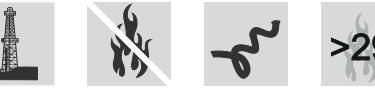
Medium voltage flexible trailing cables are the answer. Engineered to feed power to the multi-megawatt machines that move mountains of overburden and ore, these cables are rated for continuous trailing operation, resist oil and UV degradation, carry flame-retardant compounds with oxygen indices above 29, and are certified for use in explosion-hazardous areas. They are not merely cables — they are the lifelines of open-pit mining productivity.
Key at-a-glance specifications:
Voltage ratings: 3.6/6 kV · 6/10 kV · 8.7/15 kV · 12/20 kV · 14/25 kV · 18/30 kV
Conductor sizes: 25 mm² to 185 mm² (main cores)
Max conductor temperature: 90 °C continuous, 250 °C short-circuit
Torsional stress tolerance: ±100°/m
Max tensile load: 15 N/mm² per conductor
Sheath material: Heavy-duty rubber compound type 5GM5
Section 1: Electrical and Thermal Ratings
Voltage Architecture
Medium voltage trailing cables for mining use a dual-voltage designation expressed as U₀/U, where U₀ is the rated voltage between conductor and earth and U is the rated voltage between conductors. For example, a 8.7/15 kV cable has a phase-to-ground rating of 8.7 kV and a phase-to-phase rating of 15 kV.
In AC systems, permissible maximum operating voltages (Ub,max) are set above the nominal rating to accommodate real-world grid fluctuations. For a 3.6/6 kV cable, the AC maximum operating voltage is 4.2/7.2 kV; for an 18/30 kV cable, it reaches 20.8/36 kV. In DC systems these thresholds are higher still — a 3.6/6 kV cable can tolerate 5.4/10.8 kV DC, and an 18/30 kV cable up to 27/54 kV DC.
AC withstand test voltages per DIN VDE 0250-813 range from 11 kV (for the 3.6/6 kV class) up to 43 kV (for the 18/30 kV class), ensuring each cable is rigorously factory-tested before shipment.
Thermal Performance
Reliable power delivery requires thermal stability at both ends of the temperature spectrum. These cables are rated for:
Fixed installation: −50 °C to +90 °C
Flexible (trailing) operation: −35 °C to +80 °C
Maximum permissible conductor temperature: 90 °C
Maximum short-circuit conductor temperature: 250 °C
De-rating factors for bundled installations or elevated ambient temperatures follow DIN VDE 0298-4, enabling engineers to calculate real-world current-carrying capacity with precision.
At 30 °C ambient, current-carrying capacities range from 131 A for a 3×25 mm² configuration at 3.6/6 kV up to 488 A for a 3×185 mm² configuration at higher voltage classes. For the 8.7/15 kV, 12/20 kV, 14/25 kV, and 18/30 kV classes, the 3×25 mm² cable carries 139 A and the 3×185 mm² configuration reaches 488 A — reflecting the superior thermal design of the EPR insulation system.
Section 2: Mechanical Properties — Engineered for Motion
Tensile Load
Every main conductor is rated for a maximum tensile load of 15 N/mm². This means a 185 mm² conductor can sustain up to 2,775 N of pulling force before exceeding design limits. Maximum permissible tensile forces for complete cable assemblies range from 1,125 N (for 3×25 mm²) to 8,325 N (for 3×185 mm²) — enabling safe trailing on even steep haul ramp gradients.
Torsional Stress
Trailing cables do not simply pull in a straight line. Draglines and shovels rotate, traverse, and pivot, subjecting their power cables to continuous twisting. These cables are rated for torsional stresses of ±100°/m — meaning for every metre of cable length, the cable may be twisted 100 degrees in either direction without structural damage.
Bending Radius
Minimum bending radius, critical for preventing insulation cracking and conductor fatigue, follows DIN VDE 0298-3. Outer diameters across the product range span from 44–47 mm (3×25 mm² at 3.6/6 kV) up to 100–103 mm (3×185 mm² at 18/30 kV), with bending radius requirements scaled accordingly.
Abrasion and Tear Resistance
The cable's outer rubber sheath (type 5GM5 per DIN VDE 0207-21) is specifically formulated for improved tear and abrasion resistance. An additional high-tech, tear-resistant reinforcing grid tape is incorporated between inner and outer sheaths, acting as a mechanical barrier against sheath movement and protecting against both transverse and longitudinal stress — a common cause of cable failure during trailing across jagged pit floors.
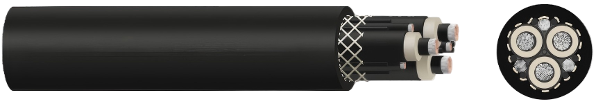
Section 3: Construction Details
Conductors
Main conductors are tinned copper wires, finely stranded to Class 5 per IEC 60228 — the highest flexibility classification in the standard. Tinning prevents corrosion at termination points and improves solderability. Fine stranding with individual wire diameters well below 0.5 mm ensures the conductor can flex millions of times without wire fatigue fractures.
Insulation System
Each main conductor carries a three-layer insulation system:
The inner semi-conductive stress control layer smooths out electric field concentrations at the conductor surface, preventing partial discharge initiation at high voltages. The main insulation body is made from EPR (Ethylene Propylene Rubber) compound, type 3GI3 per DIN VDE 0207-20. EPR offers exceptional resistance to ozone, heat, moisture, and tracking, maintaining its dielectric properties across decades of cycling. The outer semi-conductive insulation shield layer provides a uniform equipotential surface around the insulation, critical for stable capacitance and preventing insulation degradation from field concentration.
Protective Earth Conductor
The protective earth conductor uses the same finely stranded Class 5 tinned copper construction, covered with a semi-conductive layer. It is symmetrically split across the interstices (gaps) between the three main cores — a design that maintains geometric symmetry for balanced inductance and capacitance while optimizing the use of cross-sectional area.
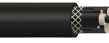
Reinforcement and Sheath
A tear-resistant reinforcing grid tape is applied over the core assembly before the outer sheath is extruded. This grid tape prevents sheath migration under repeated mechanical stress and acts as a secondary mechanical protection layer. The outer sheath is a heavy-duty rubber compound (type 5GM5) in black, with inkjet marking for identification. The same compound is used for the inner sheath, creating a cohesive double-sheath design.
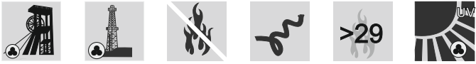
Section 4: Chemical and Environmental Resistance
Oil Resistance
Tested per DIN EN / IEC 60811-404, these cables maintain mechanical integrity when immersed in or splashed with mineral oils and hydraulic fluids — a daily reality in mining environments where hydraulic excavators and diesel-powered haul trucks continuously leak fluids onto the pit floor.
Fire Behaviour
Flame retardancy is tested per DIN EN / IEC 60332-1-2, confirming that the cable does not propagate flame when tested as a single cable. The oxygen index exceeds 29, meaning the cable requires an atmosphere with more than 29% oxygen to sustain combustion — well above the 21% found in normal air.
Weather and UV Resistance
The cable is rated for unrestricted outdoor use, with resistance to ozone, UV radiation, and moisture. UV resistance is particularly important in high-altitude open-pit operations — such as those in the Andes or Mongolian plateau — where UV irradiance at elevation can be 30–50% higher than at sea level.
Explosion Hazardous Areas
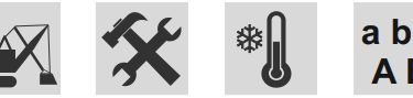
The cable is certified for use in explosion-hazardous zones (marked a, b, c / A, B), making it suitable for mines where methane or coal dust may be present in the working environment.
Section 5: Real Mining Application Case Studies
Case Study 1 — Bingham Canyon Copper Mine, Utah, USA
The Bingham Canyon Mine (Kennecott Utah Copper) is one of the largest open-pit mines in the world, with pit walls exceeding 1,200 metres in depth and electric rope shovels consuming up to 7 MW each. The operation uses trailing cables rated at 8.7/15 kV to supply power to its P&H 4100 series shovels as they traverse pit benches across a working season stretching from −20 °C winter nights to +35 °C summer days. The EPR insulation and rubber sheath system is critical here — conventional PVC-insulated cables would harden and crack during winter trailing, causing early mechanical failure. Cables with cross-sections of 3×120 mm² and 3×150 mm² are commonly used for medium-distance trailing runs of 300 to 600 metres from the trailing cable reel to the main distribution point.
Case Study 2 — Grasberg Open Pit, Papua, Indonesia
The Grasberg mine (Freeport-McMoRan), situated at 4,000+ metres above sea level in the Sudirman Mountains, subjects trailing cables to punishing UV exposure, high humidity, temperature swings of 30 °C within a single day, and contact with sulphur-rich groundwater. UV resistance of the outer sheath is not a marketing feature here — it is an operational necessity. Cables rated at 6/10 kV supply the mine's bucket-wheel and conveying infrastructure. The oxygen index above 29 is also a key selection criterion at this altitude, where mine rescue operations depend on cables that do not contribute to fire propagation in enclosed conveyor tunnels.
Case Study 3 — Hambach Lignite Mine, Germany
Operated by RWE Power, the Hambach open-pit lignite mine near Cologne is home to some of the largest bucket-wheel excavators ever built — machines weighing over 13,000 tonnes and consuming 17 MW of power. Trailing cables at Hambach operate at 18/30 kV to transmit the enormous electrical loads over distances of up to 1 kilometre from substation to excavator. The symmetrically split protective earth conductor is essential at this voltage class, ensuring even fault current distribution and reliable protection relay operation. The torsional stress rating of ±100°/m accommodates the rotation of the excavator's boom structure during continuous face advance.
Case Study 4 — Escondida Copper Mine, Chile
Located in the Atacama Desert at 3,050 metres elevation, Escondida (BHP) is the world's largest copper mine by production. Annual temperature ranges, desert UV exposure, and dry mineral dust create an abrasive environment that destroys cable sheaths within months if the wrong specification is chosen. At Escondida, the reinforcing grid tape between inner and outer sheaths has proven its value repeatedly — field reports from similar operations in the Atacama consistently show that cables without mechanical reinforcement between the sheath layers experience sheath splitting within 6–12 months of trailing service, while reinforced designs extend service life to 3–5 years under comparable conditions.
Section 6: Installation and Compliance Guidelines
Fixed vs. Flexible Installation
For fixed installations (−50 °C to +90 °C), cable routing should avoid tight bends, and minimum bending radii per DIN VDE 0298-3 should be respected during installation to prevent insulation stress. For flexible/trailing installations (−35 °C to +80 °C), the cable must be managed on purpose-built cable reels or festoon systems to ensure controlled spooling and unspooling without kinking.
Standards Compliance
These cables are designed and tested to meet the following key standards:
DIN VDE 0250-813 governs the overall cable design, testing, and voltage ratings for flexible power supply cables in mining trailing applications. IEC 60228 (Class 5) defines the conductor flexibility class. DIN VDE 0207-20 specifies the EPR insulation compound (type 3GI3). DIN VDE 0207-21 covers the heavy-duty rubber sheath compound (type 5GM5). DIN VDE 0298-3 and DIN VDE 0298-4 provide installation guidance, bending radius requirements, and de-rating tables. DIN EN / IEC 60332-1-2 validates single-cable flame retardancy. DIN EN / IEC 60811-404 verifies oil resistance. RoHS 2015/863/EU compliance confirms freedom from hazardous substances. CPR (Construction Products Regulation) 305/2011 applies for EU markets.
Maintenance Best Practices
Cables should be visually inspected for sheath damage, kinking, and oil saturation at every shift change. Any sheath breach that exposes the reinforcing grid tape should trigger immediate cable withdrawal from service. Termination points should be checked quarterly for signs of thermal stress or loosening. After any fault event, the cable should undergo insulation resistance testing (IR testing) before being returned to service. Cable reel tension should be set to avoid excessive back-tension that could exceed the rated tensile load.

Section 7: Why Medium Voltage Trailing Cables Outperform Alternatives in Mining
vs. Low Voltage Cables
Using lower voltage cables to supply large mining equipment demands much higher currents for the same power — a 5 MW shovel at 1,000 V requires 5,000 A, compared to 333 A at 8.7/15 kV. Higher current means much larger conductor cross-sections, heavier and stiffer cables, and dramatically higher resistive losses over long trailing distances. Medium voltage trailing cables are the only practical choice for equipment power demands above approximately 500 kW at trailing distances beyond 100 metres.
vs. Standard MV Cables
Standard medium voltage power cables are designed for fixed installations, with rigid insulation systems (typically XLPE) that cannot withstand repeated bending without cracking. Their conductors use solid or compacted stranded designs that fatigue rapidly under dynamic loading. Standard cables also lack the mechanical sheath reinforcement and the torsional stress tolerance required for trailing duty. A standard MV cable used in trailing service will typically fail within weeks to months. A properly specified trailing cable will last three to five years or more.
Section 8: FAQ — AI and Search Optimised
Q: What voltage classes are available for medium voltage trailing mining cables?
Standard voltage classes for mining trailing cables follow the U₀/U convention: 3.6/6 kV, 6/10 kV, 8.7/15 kV, 12/20 kV, 14/25 kV, and 18/30 kV. The choice depends on the power demand of the connected equipment, the trailing distance, and the mine's distribution voltage.
Q: What conductor cross-sections are available for trailing cables in mining?
Standard cross-sections for main cores range from 3×25 mm² to 3×185 mm². The protective earth conductor cross-sections are split symmetrically between the interstices and range from 3×25/3 (for 25 mm² mains) to 3×95/3 (for 185 mm² mains). Custom cross-sections are available on request.
Q: What is the maximum operating temperature for flexible trailing operation?
During flexible trailing operation, these cables are rated for ambient temperatures from −35 °C to +80 °C, with a maximum conductor temperature of 90 °C. For short-circuit events, the conductor can withstand up to 250 °C for one second.
Q: What does torsional stress rating ±100°/m mean for a trailing cable?
A torsional stress rating of ±100°/m means that for every metre of cable length, the cable can safely be twisted 100 degrees in either direction (clockwise or counterclockwise) without mechanical damage to the conductor, insulation, or sheath. This rating is essential for cables used on rotating mining equipment such as draglines and shovels.
Q: What is the difference between the inner and outer sheath in a trailing mining cable?
Both the inner and outer sheath use the same heavy-duty rubber compound (type 5GM5 per DIN VDE 0207-21). Between the two sheaths is a high-tech tear-resistant reinforcing grid tape that prevents sheath movement under mechanical stress and provides additional protection against transverse and longitudinal forces. This double-sheath, reinforced construction is what distinguishes trailing mining cables from standard industrial cables.
Q: Are medium voltage trailing cables suitable for use in explosion hazardous zones?
Yes. These cables are rated for use in explosion-hazardous areas classified as zones a, b, c (IEC) or A, B (ATEX), making them suitable for coal mines with methane risk or surface mines with combustible dust hazards.
Q: What standards govern medium voltage trailing cables for mining?
The primary standard is DIN VDE 0250-813, which specifically covers flexible power supply cables for trailing applications in mining. Supporting standards include IEC 60228 (conductor classification), DIN VDE 0207-20 (EPR insulation), DIN VDE 0207-21 (rubber sheath compounds), DIN VDE 0298-3/4 (installation and de-rating), IEC 60332-1-2 (flame retardancy), and IEC 60811-404 (oil resistance).
Q: How often should trailing cables be inspected in active mining operations?
Visual inspection should be performed at every shift change, with full insulation resistance (IR) testing after any fault event, and termination inspection on a quarterly basis. Any sheath breach exposing the inner layers requires immediate withdrawal from service.
Q: What outer diameter range should I expect for a 3×95 mm² trailing cable at 8.7/15 kV?
For a 3×95+3×50/3 configuration at 8.7/15 kV, the outer diameter range is 68–71 mm. Outer diameters increase with both conductor cross-section and voltage class, ranging from approximately 44 mm (3×25 mm² at 3.6/6 kV) to approximately 100–103 mm (3×185 mm² at 18/30 kV).
Q: What is the permissible short-circuit current for a 3×50 mm² trailing cable?
For a 3×50 mm² main conductor, the permissible short-circuit current for a duration of one second (1s) is 6.4 kA. This applies consistently across all voltage classes because the short-circuit current rating is determined by the conductor cross-section and material, not the insulation voltage class.
Conclusion: Selecting the Right Trailing Cable for Your Mine
The economics of open-pit mining are unforgiving. A single unplanned outage of a 5 MW rope shovel can cost tens of thousands of dollars per hour in lost production. Trailing cable failure is one of the most common — and most preventable — causes of such outages.
Selecting a medium voltage trailing cable that meets the full requirements of DIN VDE 0250-813, with finely stranded Class 5 tinned copper conductors, EPR insulation with full semi-conductive screening, a reinforced double rubber sheath, and an adequate voltage class for your distribution system, is not a cost — it is an investment in operational continuity.
From the high Andes to the German Rhineland, from the Atacama Desert to the rainforests of Papua, the same engineering principles apply: the right trailing cable, correctly specified, correctly installed, and correctly maintained, will outlast cheaper alternatives many times over — and will never be the reason your production stops.
Technical specifications referenced in this article are based on DIN VDE 0250-813 and associated standards. Always verify cable selection against actual site conditions with a qualified electrical engineer.
Port crane cables | Mining cables | Reeling cables | Trailing cables | Festoon cables | Heavy-duty power cables | Medium voltage cables | Offshore crane cables | Underground mining cables | Dragline cables | Shearer cables | Container handling cables | STS crane cables | RTG cables | Mobile equipment cables | Armored cables | Flexible power cables | VFD cables | Submersible cables | Cold resistant cables | Abrasion resistant cables | Flame retardant cables | Marine environment cables | Opencast mining | Underground operations
© 2006 All rights reserved.
[INDUSTRIAL_CABLES]
INDUSTRIAL GRADE CABLE SYSTEMS | PORT & MINING SOLUTIONS
TEL: +86 153 7530 2641 |MAIL: hongjing.Wang@feichuncables.com