(N)TSCGEWÖU+LWL Medium Voltage Power Cable VDE 0250 – Flexible LSZH Crane Cable for Power and Data Transmission
Discover the features and technical advantages of the (N)TSCGEWÖU+LWL medium voltage power cable with VDE 0250 certification. Designed for cranes and reeling systems, this halogen-free, flexible cable combines power and fiber optics for safe operation and long service life in demanding environments.
CRANE CABLE
hongjing.Wang@Feichun
2/28/20269 min read
Modern crane and reeling systems demand far more than conventional high-voltage conductors. Port gantries, ship-to-shore cranes, rubber-tyred gantries (RTGs), and automated stacking cranes must endure continuous flexion, high-speed pay-out, torsional stress, maritime salt spray, and simultaneous data transmission — all without a single unplanned shutdown. The electrical cable has become, in effect, the backbone of the crane's operational reliability.
The (N)TSCGEWÖU+LWL medium voltage power cable was engineered specifically to meet these compounding demands. Certified to VDE 0250 Part 813 and harmonised under HD 620 S2, this cable integrates extra-flexible power conductors with embedded optical fiber in a single, mechanically robust assembly. Operating voltages span 3.6/6 kV to 12/20 kV, covering the full range of modern electrified port crane applications.
The designation itself encodes the construction: N indicates a standard national design, T refers to elastomeric insulation, SC denotes screened cores, G indicates a braided armour layer, EW signifies extra-flexible conductors, Ö is the halogen-free LSZH outer sheath, U indicates UV resistance, and +LWL (Lichtwellenleiter) denotes the integrated optical fiber unit. Understanding this designation allows engineers to read and specify cable variants with precision.
Introduction: Next-Generation Crane Cable Technology
Compliance and Standards: Built for Safety and Reliability
VDE 0250 Part 813 is the governing standard for flexible reeling cables in Germany, harmonised internationally through HD 620 S2 under CENELEC. These standards go well beyond the requirements placed on general-purpose flexible cables, addressing the specific mechanical, electrical, and fire-performance needs of drum-reel applications.
From a fire safety perspective, the LSZH (Low Smoke Zero Halogen) designation imposes strict limits on hydrogen chloride emission during combustion — below 0.5% per IEC 60754 — and mandates minimum light transmittance of 60% during combustion per IEC 61034. These requirements matter enormously in enclosed port terminal buildings and machine rooms, where halogenated cable fires produce dense, corrosive smoke that damages sensitive electronics and impairs evacuation. Additional compliance references for marine and offshore applications include IEC 60092-353 for flame propagation and oil resistance, which applies to vessel-mounted and quayside installations.
Construction Design: Strength in Every Layer
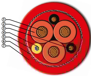
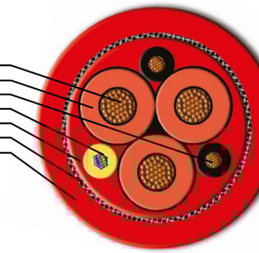
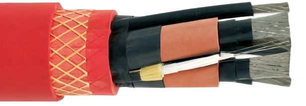
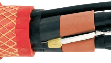
Understanding the layered construction of the (N)TSCGEWÖU+LWL cable is essential for correct specification. Each layer solves a specific mechanical or electrical problem unique to reeling applications.
At the core, Class 6 fine-wire stranded copper conductors per IEC 60228 provide the extra flexibility required for continuous drum operation. This stranding class is non-negotiable for reel use — specifying Class 2 conductors in a reeling cable causes conductor fatigue cracking within a fraction of the intended service life. Over the conductor sits a semiconductive screen to control field distribution, followed by HEPR (Hard Ethylene Propylene Rubber) insulation rated for 90°C continuous operation and selected for its excellent partial-discharge resistance under cyclic mechanical stress. A second semiconductive insulation screen and a metallic copper screen complete the electrical architecture, providing both a fault current return path and EMI shielding.
The optical fiber unit is housed in a gel-filled central tube with its own aramid tensile strength member, physically isolating the glass fiber from the flex and torsion loads carried by the power core assembly. Single-mode fiber (OS2) suits distances above 550 m or future data rates above 1 Gbit/s; multimode fiber (OM3/OM4) serves most crane encoder, Profibus, and Profinet applications within standard drum run lengths.
The anti-torsion element assembly — opposing-lay filler elements positioned between the power cores — is one of the most important features distinguishing a true reeling cable from an adapted flexible cable. Reeling cables rotate axially as they wind and unwind on the drum. Without counter-spiral reinforcement, accumulated torsion causes core migration, insulation cracking, and the characteristic "pigtailing" that causes cable to jump off the drum. The anti-torsion architecture creates torsional equilibrium, allowing the cable to resist rotation in both directions without accumulating residual stress. An abrasion-resistant inner sheath and the outer sheath — LSZH (Ö) or polychloroprene (5GM3/5GM5) — complete the structure.
Material Superiority: LSZH and Polychloroprene Options
The outer sheath specification reflects fundamental decisions about fire safety policy, environmental exposure, and total cost of ownership.
LSZH (halogen-free) sheaths, designated Ö, satisfy the fire safety requirements of modern enclosed port infrastructure. They emit minimal smoke and no corrosive halogen gases during combustion, protecting both evacuation routes and sensitive crane control electronics. UV-stabilised and oil-resistant LSZH grades are available for exposed or hydraulic-adjacent installations. Most major terminal operators in Europe, the Middle East, and Asia now mandate LSZH sheathing by policy.
Polychloroprene sheaths, offered in standard (5GM3) and heavy-duty (5GM5) grades, have a proven track record in outdoor industrial environments. They offer excellent ozone resistance, robust abrasion resistance, and a lower unit cost. Their limitation is halogen content: combustion produces hydrogen chloride gas. For purely outdoor, well-ventilated applications where fire spread risk is demonstrably low, polychloroprene remains a technically valid choice. Where any doubt exists, LSZH should be the default — its lifecycle cost advantage, when reduced insurance risk and regulatory compliance are factored in, consistently outweighs the unit price premium.
Performance in Motion: Designed for Crane and Reel Applications
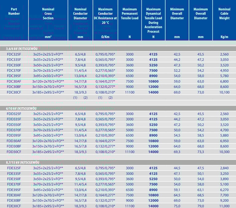
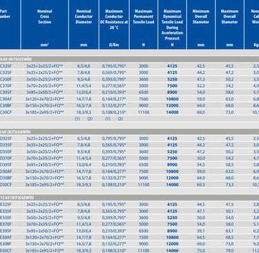
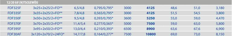
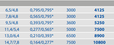
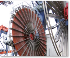
The (N)TSCGEWÖU+LWL cable is qualified for both end-feed and center-feed drum reeling systems. The supported voltage range of 3.6/6 kV to 12/20 kV covers all common medium-voltage crane power systems. Engineers working with unearthed (IT) networks must specify the next voltage class above the nominal system voltage — for example, 8.7/15 kV for a nominal 10 kV IT system — because the full line voltage appears across healthy phase insulation during a single-phase earth fault.
Mechanically, the cable is rated for reel speeds up to 300 m/min, covering all current container crane operating profiles including high-productivity automated terminals. The cable must remain under continuous moderate tension throughout the pay-out and reel-in cycle: slack pay-out causes transverse kinking, one of the most common causes of premature failure in the field. The tensioner system is responsible for maintaining this tension, but the specifying engineer must confirm that the cable's tensile load rating is compatible with the tensioner force profile across the full drum diameter range.
The minimum dynamic bending radius of 8 times the overall cable diameter, as required by VDE 0250 Part 813, translates directly into a minimum drum core diameter. For a 50 mm OD cable, the drum core must be at least 400 mm. Engineers who design drum geometry to the static bending radius and then use that drum for dynamic reeling will initiate insulation cracking within the first year of operation.
Step-by-Step Cable Selection Method
The following seven steps translate application requirements into a fully specified (N)TSCGEWÖU+LWL cable variant. Work through each step sequentially — skipping steps is the primary cause of undersized or over-stressed selections.
Step 1 — Define System Voltage and Insulation Level. Confirm the nominal operating voltage (U0/U) and the network earthing arrangement. For solidly earthed systems, the insulation level matches the nominal voltage class. For unearthed or impedance-earthed systems, specify the next voltage class up, as the full phase-to-phase voltage can appear across a healthy conductor during a single-phase earth fault.
Step 2 — Calculate Current-Carrying Capacity and Conductor Cross-Section. Apply IEC 60364-5-52 derating factors for ambient temperature, drum layering, and installation method. Cable wound on a drum dissipates heat poorly — a derating factor of 0.7 to 0.8 times the published flat-laid ampacity is a widely accepted starting point. For conductors above 95 mm², use thermal modelling to confirm the final cross-section.
Step 3 — Determine Minimum Bending Radius and Drum Core Diameter. VDE 0250 Part 813 requires a dynamic bending radius of at least 8 times the cable outer diameter, applied to the innermost drum layer. The drum core diameter must therefore be at least 16 times the cable outer diameter. Verify this against the drum mechanical drawing before fabrication — changing drum geometry after manufacture is significantly more expensive than correcting a cable specification at the design stage.
Step 4 — Establish Maximum Tensile Load. Calculate tensile force at maximum drum speed during pay-out and reel-in, including suspended cable weight and a dynamic load factor of at least 1.25 to cover acceleration, deceleration, and wind loading. For festoon configurations, include sag geometry. For vertical drops exceeding 20 m, the weight of suspended cable alone can be the design-critical load. The result must not exceed the manufacturer's rated maximum tractive force.
Step 5 — Specify Reel Speed and Verify Flex Cycle Life. Confirm maximum reel speed from the crane drive specification. Request the manufacturer's flex endurance curve — cycles to failure at the specified bending radius and cross-section — and verify that rated cycle life exceeds the crane's expected duty over its full design service life. A container crane at high utilisation may complete 10 to 15 million reel cycles over 25 years; this number must be explicitly compared against the published endurance data.
Step 6 — Assess Environmental Conditions. Document ambient temperature range, UV exposure, chemical exposure (hydraulic oil, seawater, de-icing salts), and any ATEX zone classifications. Specify LSZH for all enclosed or semi-enclosed structures. For cable near hydraulic lines, request Type 2 oil-resistant LSZH per IEC 60811-404. For northern climate installations, require cold-bend testing per IEC 60811-504 at minus 40°C and obtain test certificates, as LSZH compounds vary significantly in low-temperature flexibility.
Step 7 — Select Fiber Optic Specification. Confirm communication protocol, required data rate, and maximum cable run length. For spans under 500 m and Profinet at 100 Mbit/s, OM3 multimode is cost-effective. For gigabit applications or runs above 1 km, specify OS2 single-mode. Determine the fiber count from the control system I/O topology and add a minimum 25% spare allowance, rounded up to the next standard bundle size (4F, 8F, or 12F). Spare capacity avoids the costly scenario of replacing an entire cable assembly to add two fibers during a future automation upgrade.
Common Crane Cable Selection Mistakes — and How to Avoid Them
Field failures in crane cable installations are rarely caused by manufacturing defects. The overwhelming majority trace back to specification errors made at the design stage.
Mistake 1 — Specifying standard flexible cable instead of reel-rated cable. General-purpose flexible cables such as H07RN-F lack anti-torsion architecture, Class 6 conductor optimisation, and the screen design required for continuous drum use. Core migration and insulation cracking typically appear within 50,000 to 100,000 cycles. Any cable used in a reel application must be certified to VDE 0250 Part 813.
Mistake 2 — Undersizing the drum core diameter. Designing the drum to the static bending radius (5 × OD) rather than the dynamic radius (8 × OD) required by VDE 0250 Part 813 initiates insulation cracking within the first year of operation. This error is discovered only after the drum has been fabricated and the crane is in service.
Mistake 3 — Ignoring drum derating for thermal ampacity. Cable on a drum in a hot machine room may carry 40 to 50 percent less current than the published datasheet value. Failing to apply derating factors results in overheating, accelerated insulation ageing, and nuisance tripping — or, in the worst case, insulation failure.
Mistake 4 — Running a separate signal cable on the same drum. Two cables on the same drum tangle, abrade each other, and produce intermittent signal faults from uneven winding. The integrated LWL unit in (N)TSCGEWÖU+LWL eliminates this problem entirely by housing both power and fiber in a single engineered structure.
Mistake 5 — Accepting LSZH without cold-temperature verification. Some standard LSZH compounds become brittle above minus 10°C and crack during cold-climate installations or overnight winter standstill. For any northern climate application, cold-bend testing at minus 40°C per IEC 60811-504 must be explicitly required and certificates reviewed before cable acceptance.
Mistake 6 — Under-specifying fiber count with no spare capacity. Specifying exactly the number of fibers in the current design means the next automation upgrade requires replacing the entire cable assembly. A 25% spare fiber allowance costs almost nothing at installation and avoids significant downtime and expense later.
Mistake 7 — Applying land-rated cable in marine environments without verifying oil and salt resistance. VDE 0250 Part 813 certification does not imply IEC 60092-353 marine compliance. For quayside, vessel-adjacent, or hydraulic-exposed installations, Type 2 oil-resistant LSZH sheathing and marine flame propagation certification must be specified explicitly and confirmed in writing by the manufacturer.

Proven Reliability in Global Ports
The (N)TSCGEWÖU+LWL cable platform has accumulated substantial operational hours across ship-to-shore cranes, automated stacking cranes, and RTGs in terminals across Northern Europe, the Middle East, and East Asia. The integrated fiber design reduces commissioning time by eliminating separate signal cable routing and fault-finding. The anti-torsion construction extends mean time between replacements to 15 to 20 years under rated duty cycles — compared to 5 to 8 years commonly observed with non-optimised flexible cable solutions adapted for reel use.
Lifecycle cost modelling consistently shows that the higher upfront cost of (N)TSCGEWÖU+LWL is recovered within the first avoided replacement cycle, with further savings from reduced crane downtime and lower maintenance labour. Project engineers are strongly encouraged to present lifecycle cost analysis — not unit price per metre — when justifying this specification during tender evaluation.
Conclusion: Power and Communication Combined for the Future of Material Handling
The (N)TSCGEWÖU+LWL medium voltage cable represents the mature integration of high-voltage power delivery and digital communication within a single, purpose-engineered structure certified to VDE 0250 Part 813 and HD 620 S2. Its LSZH sheathing addresses the fire safety requirements of modern enclosed port infrastructure. Its Class 6 conductors, anti-torsion architecture, and HEPR insulation deliver the mechanical endurance that separates a long-service asset from a recurring maintenance liability.
For crane manufacturers and project engineers, the seven-step selection method in this guide provides a structured, defensible approach covering every critical parameter from voltage class to fiber count. For applications requiring custom voltage classes, non-standard cross-sections, ATEX terminations, or enhanced oil resistance, engage the manufacturer's application engineering team early in the design process — customised cable configurations are routinely available and, when correctly specified, represent the most cost-effective long-term solution for demanding crane and reeling applications.
Port crane cables | Mining cables | Reeling cables | Trailing cables | Festoon cables | Heavy-duty power cables | Medium voltage cables | Offshore crane cables | Underground mining cables | Dragline cables | Shearer cables | Container handling cables | STS crane cables | RTG cables | Mobile equipment cables | Armored cables | Flexible power cables | VFD cables | Submersible cables | Cold resistant cables | Abrasion resistant cables | Flame retardant cables | Marine environment cables | Opencast mining | Underground operations
© 2006 All rights reserved.
[INDUSTRIAL_CABLES]
INDUSTRIAL GRADE CABLE SYSTEMS | PORT & MINING SOLUTIONS
TEL: +86 153 7530 2641 |MAIL: hongjing.Wang@feichuncables.com