
Reeling Cable, Festoon Cable, Spreader Cable, and Fiber Optic Cable — A Complete Guide for Port Engineers and Procurement Teams
Reeling, festoon, spreader, encoder & fiber optic cables for RTG cranes. A practical guide to electrification, failure modes and R-(N)TSCGEWOEU / NSHTOEU cables.
hongjing.Wang@Feichun
6/25/202624 min read
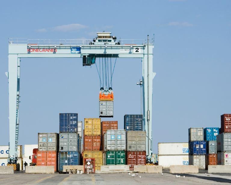
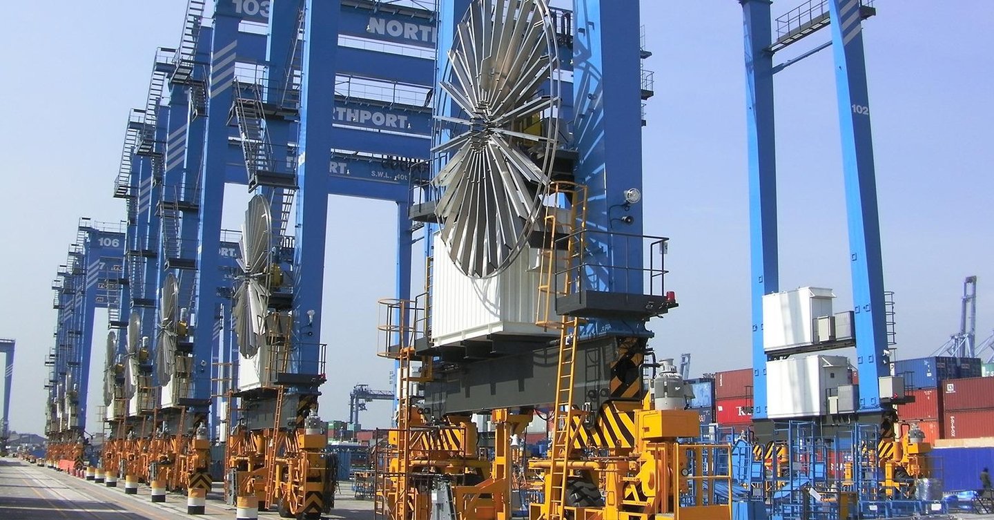
In the container yards of the region's great ports, away from the dramatic skyline of the quayside, a different kind of crane does the patient work that keeps a terminal flowing. It moves between long rows of stacked containers, lifting, repositioning, and organizing the steel boxes that arrive faster than they can be cleared. This is the rubber-tyred gantry crane, known almost universally as the RTG, and it is one of the most widely used container handling machines in ports across the world. If the ship-to-shore crane is the muscle that moves containers between ship and shore, the RTG is the workhorse that manages them once they are on land, and the efficiency of the stacking yard depends on it almost completely.
The RTG is a deceptively demanding machine to power. Because it travels up and down the rows of the container yard, often over considerable distances and through many cycles each shift, the electrical and control cables that serve it must support long-distance travel, frequent movement, and all of this in the harsh coastal environment that every port shares. The cable systems of an RTG live a hard life, flexing and winding through every working hour while enduring salt-laden air, intense sun, and the constant mechanical activity of a machine that never stops for long. Their selection is not a peripheral concern but a central one, because a cable that fails on an RTG can stop that crane just as surely as a mechanical breakdown, with the same painful consequences for the yard's productivity.
The cost of cable failure on an RTG is felt directly in three places: crane uptime, safety, and terminal productivity. A reeling cable that wears through and faults can take the crane offline in an instant. A control cable that fatigues can interrupt the signals that keep the machine operating safely. And every hour an RTG stands idle is an hour in which containers pile up, vehicles wait, and the smooth choreography of the yard breaks down. For this reason, the selection of RTG cables deserves the same engineering rigor that any other critical component receives.
This guide is written for the engineers, procurement specialists, and project planners who carry that responsibility. It explains what an RTG is and the forms it takes, how RTGs are powered, which cables serve which functions, the conditions those cables must survive, how they fail, and how to assemble a complete cable solution rather than a single product. As with any sound engineering decision, the approach here is to build understanding patiently, so that by the end you can specify an RTG's cabling with genuine confidence.
1. Introduction: The Workhorse of the Container Yard
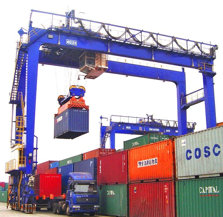
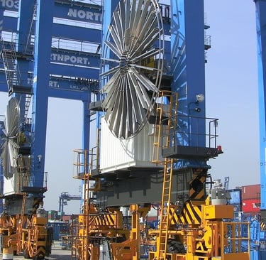
The rubber-tyred gantry crane takes its name from its defining feature: unlike the rail-mounted cranes that run on fixed tracks, the RTG moves on rubber tyres, giving it the freedom to travel not only along a row of stacked containers but, when needed, to be steered across the yard to a different stack entirely. This mobility is what makes the RTG so versatile and so widely adopted. A single RTG can serve multiple container stacks, moving where the work is, and a fleet of RTGs gives a terminal enormous flexibility in how it organizes its yard. It is this combination of lifting capability and mobility that has made the RTG the dominant yard crane in container terminals around the world.
That same mobility, however, is exactly what makes RTG cabling challenging. A machine that moves must be fed power and control signals while it moves, and the cables that do this must accommodate the motion without failing. An RTG travels long distances along its rows, reels and unreels its power cable through countless cycles, and does so in the open air of a coastal port. The result is a set of demands, long travel, frequent movement, mechanical stress, and harsh environmental exposure, that ordinary cables simply cannot meet. The cables that serve an RTG reliably are those engineered specifically for this combination of motion and environment.
As with any complex machine, an RTG does not rely on a single cable but on a coordinated family of them, each suited to a different function and a different kind of movement. The principal categories are the reeling cable that supplies the crane with power as it travels, the festoon cable used in suspended moving cable systems, the spreader cable that serves the most dynamic part of the machine, the encoder cable that carries the feedback signals for motion control, and the fiber optic cable that handles high-speed data and communication. Understanding each of these, and how they work together, is the foundation of a sound RTG cable solution, and it is the subject of this guide.
2. RTG Crane Types: From Diesel to Fully Electric
Before examining the cables, it is worth understanding that the RTG is not a single fixed design but a family of machines that have evolved considerably, particularly in how they are powered. The trend across the industry has been a steady move away from diesel toward electric power, driven by concerns about emissions, energy cost, and sustainability. Understanding where a particular RTG sits on this spectrum matters, because the power system has a direct bearing on the cabling required.
The diesel RTG is the traditional form of the machine, powered by an onboard diesel engine that drives a generator to supply the crane's electric motors. The great advantage of the diesel RTG is its complete independence: it carries its own power source and can move anywhere in the yard without any external electrical connection. This flexibility made diesel RTGs the standard for many years and they remain in widespread use. The drawbacks, however, have become increasingly important. Diesel RTGs consume significant quantities of fuel, with the associated running costs, and they produce exhaust emissions and noise that are increasingly unwelcome in modern ports under pressure to reduce their environmental footprint. The diesel RTG is flexible, but its fuel consumption and emissions are a growing liability.
The hybrid RTG represents an intermediate step, combining a diesel engine with an electric energy storage and power system. By capturing energy during lowering and braking and storing it for reuse, and by allowing the diesel engine to run more efficiently or to be downsized, the hybrid RTG can reduce fuel consumption and emissions substantially while retaining much of the operational flexibility of the pure diesel machine. The hybrid approach appeals to terminals that want to cut fuel use and emissions without committing to the infrastructure of a fully electric system, offering a balance between environmental performance and operational independence.
The electrified RTG, commonly referred to as the E-RTG, takes the decisive step of drawing its power from an external electrical supply rather than from an onboard engine. An E-RTG is connected to the terminal's electrical grid through a power supply system, most commonly a cable reel or a busbar arrangement, and runs its motors directly from this supply. E-RTGs have become increasingly popular precisely because they eliminate the fuel consumption and local emissions of the diesel machine, offering lower operating costs and a dramatically reduced environmental impact. The shift to E-RTG operation is one of the most significant trends in container terminal electrification, and it places the power supply cable at the very heart of the machine's operation.
The fully electric RTG is the complete realization of this trend, a crane that runs entirely on an electric power supply with no onboard combustion engine at all. Such machines are the natural choice for terminals that have made energy efficiency and sustainability central to their operations, offering the lowest emissions and, over time, attractive operating economics. The fully electric RTG depends entirely on its electrical connection to the yard's supply, which makes the reliability and quality of its power cabling not merely important but absolutely fundamental to its ability to work at all.
The clear direction of this evolution, from diesel toward hybrid, electrified, and fully electric machines, has a direct consequence for cabling. As RTGs become electric, the power supply cable becomes the lifeline of the machine, and its selection becomes ever more critical. The remainder of this guide focuses primarily on the cabling of electrified and electric RTGs, where the cable system carries the full responsibility for keeping the crane powered.
3. RTG Power Supply Systems: How Electricity Reaches the Moving Crane
For an electrified RTG to work, electrical power must be delivered to it while it moves along its rows. Several systems exist to accomplish this, and the choice of system shapes the cabling requirements of the crane. Understanding the main power supply systems is therefore an essential step toward understanding RTG cabling.
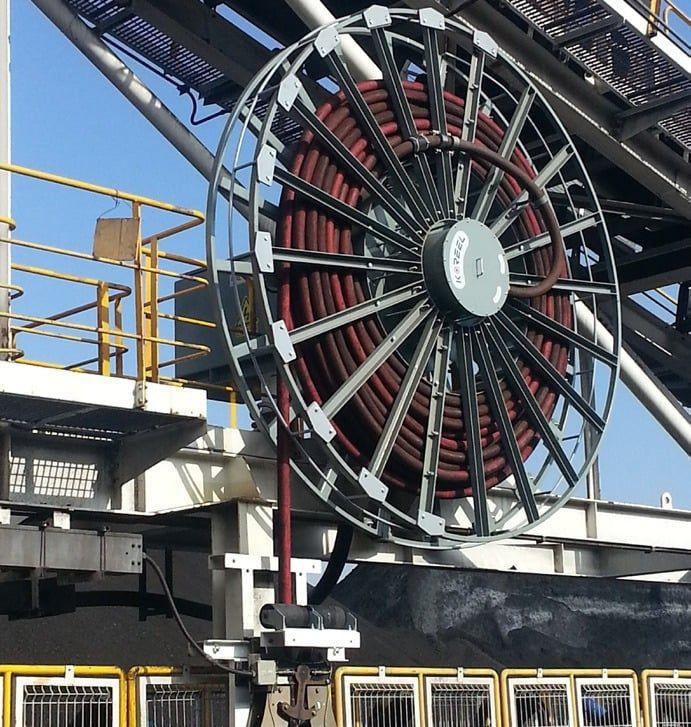
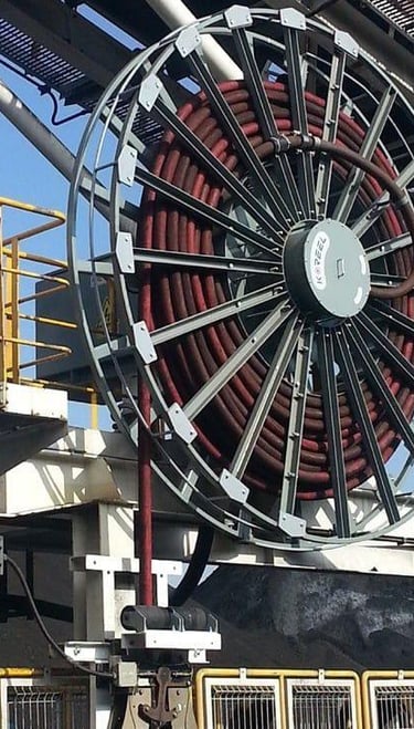
The cable reel system is one of the most important and widely used electrification solutions for RTGs. In this arrangement, a motorized reel mounted on the crane stores a length of reeling cable, paying it out as the crane travels away from its supply point and drawing it back in as the crane returns. One end of the cable connects to a fixed supply point in the yard, and the other feeds the crane, so that as the RTG moves, the reel manages the cable continuously, keeping it under controlled tension and winding it neatly. The cable reel system is especially well suited to applications involving long travel distances and frequent operation, because the motorized reel can manage the cable smoothly across the full length of the crane's travel and through the many cycles of a working shift. For the great majority of electrified RTGs, the cable reel system, and the reeling cable at its heart, is the primary means of electrification.
The busbar system takes a different approach, supplying power through a fixed conductor path rather than a moving cable. In this arrangement, a continuous conductor, the busbar, runs along the crane's travel path, and a collector mounted on the crane slides along the busbar to draw power as the crane moves. The busbar system is often used where the movement path is predictable and well controlled, since the fixed conductor must follow the crane's route precisely. It offers certain advantages in some installations, but it requires the infrastructure of the busbar to be installed along every travel path, and it is generally less flexible than the cable reel approach when the crane's movements are more varied. Where it is used, the busbar still relies on cabling for the connections between the collector and the crane's systems.
The cable chain system, sometimes called a cable carrier or drag chain system, is used to guide moving cables safely along a defined path. In this arrangement, the cable is carried inside an articulated chain that supports and protects it as it extends and retracts, controlling its movement and preventing it from tangling, twisting, or being damaged. The cable chain system is more commonly used for auxiliary movement, control, or data applications than for the main power supply of a large RTG, but it plays an important role in managing the secondary cables that must move with parts of the machine. Cables intended for cable chain service must be flexible and built to endure the constant bending that chain operation imposes, much like festoon cables.
The choice among these systems depends on the specific terminal, its layout, and its operational patterns. For the long travel and frequent operation typical of most RTG applications, the cable reel system with a heavy-duty reeling cable is the dominant solution, and it is the reeling cable that becomes the single most important cable on the electrified RTG.
4. Main Cable Types on RTG Cranes: A Cable for Every Function
With the power supply systems understood, we can examine the main cable types that serve an RTG, considering what each does and what it must withstand.
Reeling Cable
The reeling cable is the main power cable for RTG crane movement, the lifeline that delivers electricity to the machine as it travels along its rows. Wound onto and off a motorized reel, it pays out and draws back continuously as the crane moves, carrying the full electrical load of the machine through every cycle of every shift. This makes it the most important cable category in RTG electrification, the cable on which the crane's ability to work most directly depends.
A reeling cable must withstand a formidable combination of stresses. It must resist the repeated bending that occurs as it winds around the reel drum, the tension that arises as it is pulled along by the moving crane, the abrasion that comes from rubbing against itself and against guides during winding, and the cumulative fatigue of repeated winding cycles over a long service life. To meet these demands, a quality reeling cable is built from the inside out for dynamic service. Its conductors are made of finely stranded tinned copper wires of a high flexibility class, allowing the cable to bend repeatedly without the conductors fatiguing and breaking. Its insulation is a special rubber compound based on ethylene propylene rubber chemistry, chosen for its combination of electrical strength, heat resistance, and mechanical flexibility. Around the cores, the interstices are filled with a heavy-duty rubber compound, and the whole assembly is reinforced with a braid of synthetic threads bonded between an inner and outer sheath, a construction that gives the cable the strength to resist the simultaneous tensile and torsional stresses of reeling. The outer sheath is a tough, heavy-duty rubber compound formulated to resist abrasion, oil, ozone, ultraviolet light, and moisture.
The mechanical ratings of such a cable tell the story of its purpose. A typical heavy-duty reeling cable is rated for a static tensile load of around fifteen newtons per square millimeter and a higher dynamic tensile load, around twenty newtons per square millimeter, to account for the additional forces during acceleration. It can withstand torsional stress of around twenty-five degrees of twist per meter of length, a significant capability that reflects the twisting that reeling imposes. Its reeling speed may be rated up to around one hundred and twenty meters per minute, and its bending radius requirements vary by situation: it can tolerate a tighter radius for fixed installation, perhaps around four times the cable diameter, but requires a more generous radius for reeling application, around six times the diameter, and more still when running over deflection pulleys, around seven and a half times the diameter. These ratings are not abstract numbers; they are the constraints that the reel and drum system must be designed to respect, because a reel that bends the cable more tightly than its rated radius will destroy the cable prematurely no matter how well it is otherwise built.
For the main power supply of an RTG, where the supply is at low voltage, a heavy-duty low voltage reeling cable rated at 0.6/1 kilovolt is the appropriate solution, designed specifically for the simultaneous tensile and torsional stress of motorized mono-spiral, cylindrical, or spring-operated reels. Where the RTG is supplied at medium voltage, a medium voltage reeling cable of the corresponding heavy-duty construction is used instead, bringing the efficiency and reduced voltage drop that medium voltage supply offers over long travel distances. In both cases, the principle is the same: the reeling cable is the heart of RTG electrification, and it must be chosen for the precise mechanical and electrical demands of the application.
Festoon Cable
The festoon cable is used in moving suspended cable systems, where cables must travel with a part of the machine while remaining supported along their length. In a festoon arrangement, the cable is suspended from a series of carriers that gather together and spread apart as the moving part travels, allowing the cable to extend and retract smoothly like the folds of a curtain. This arrangement is well suited to applications requiring repeated flexing and guided movement, and it provides a controlled, supported path for cables that must accompany a moving element of the crane.
A festoon cable must endure the repeated bending of gathering and extending, the lateral motion of the festoon folding open and closed, and the suspended travel of hanging in the festoon system. Because these movements repeat continuously, the festoon cable accumulates a great many bending cycles over its life and must be built to endure them without fatigue. Quality festoon cables are constructed from finely stranded flexible conductors with robust elastomer insulation and sheathing, and where they carry control or data signals, they often include a copper braid screen to protect those signals from the electromagnetic interference generated by the crane's motors. Such cables are typically rated for high travel speeds in festoon systems and are built specifically for the high mechanical stress and frequent bending that festoon operation imposes.
Spreader Cable
The spreader cable connects to the spreader, the device that grips the container, and it must handle continuous dynamic movement as the spreader descends, lifts, and retracts through every cycle. This is the cable that operates in the most dynamic zone of the crane, enduring the most frequent flexing and the swing and sway that come with handling suspended loads. To survive this duty, a spreader cable needs high flexibility to coil and extend without fatigue, strong abrasion resistance to withstand the constant rubbing against guides and surfaces, and a compact construction that keeps weight and bulk to a minimum so the cable can move cleanly with the spreader.
For this demanding application, a cable with a polyurethane outer sheath is widely preferred. Polyurethane offers an excellent combination of abrasion resistance, flexibility, and outdoor durability, making it well suited to the severe, repetitive, weather-exposed environment of the spreader. A polyurethane-sheathed spreader cable can take the mechanical punishment of continuous lifting while remaining flexible and compact, and where the spreader carries sensors or other data-generating systems, the cable can incorporate fiber optic cores to carry that data alongside the power and control conductors.
Encoder Cable
The encoder cable is used for signal feedback and motion control, carrying the precise position and movement information that the crane's control systems need to operate accurately. Encoders are the sensors that measure position, speed, and rotation, and the encoder cable conveys their signals to the control system, enabling the accurate positioning of the crane, the trolley, and the spreader. As terminals automate and demand ever greater precision in container handling, the encoder cable becomes increasingly important, because accurate positioning and automation depend on the reliable transmission of these feedback signals. An encoder cable must be flexible enough to accompany the moving parts it serves, and it typically requires screening to protect its sensitive low-level signals from interference, since any corruption of the feedback signal can degrade the precision of the crane's motion.
Fiber Optic Cable
The fiber optic cable is used for high-speed communication and data transmission, carrying the large volumes of information that modern automated terminals require. Fiber optic transmission offers enormous bandwidth, immunity to electromagnetic interference, and the ability to carry data over long distances without degradation, making it the technology of choice for the communication links of a modern RTG. Fiber supports the smart-port automation, the control systems, and the monitoring functions that increasingly define competitive terminals, carrying everything from control commands and diagnostic data to the images from cameras and the readings from sensors. In many installations, fiber optic cores are integrated directly into the power or control cables, so that data and power move together through the moving zones of the crane, simplifying the installation and giving the data link the same robust mechanical protection as the power conductors. As RTGs become electrified and automated, fiber optic cabling becomes an essential part of the complete solution.
5. RTG Operating Conditions: The Stresses the Cable Must Survive
The cables of an RTG must perform reliably under a set of operating conditions that combine heavy mechanical stress with harsh environmental exposure. Understanding these conditions explains why RTG cables must be built to such demanding standards.
The first condition is long-distance movement along the yard. RTGs travel considerable distances as they work their rows and move between stacks, and the reeling cable must accommodate this entire travel range. Over a long travel path, the cable is wound and unwound through many cycles, each imposing mechanical stress, and the cumulative effect over a long distance is substantial. The cable must have the endurance to survive years of this continuous winding without degradation.
The second condition is frequent reeling and unreeling cycles. An RTG does not travel once and stop; it moves repeatedly throughout each shift, reeling and unreeling its cable again and again. Each cycle flexes and stresses the cable, and the sheer number of cycles over the cable's life is enormous. This relentless cycling demands a cable with exceptional fatigue resistance, built from finely stranded conductors and resilient materials that can endure the repeated working without failure.
The third condition is torsion and twisting stress. As a reeling cable winds onto and off a drum, particularly with mono-spiral and cylindrical reels, it is subjected to torsional stress, twisting about its own axis. Repeated twisting is one of the most demanding stresses a cable can experience, working the internal structure in a way that simple bending does not. This is why quality reeling cables specify a permissible torsional stress and incorporate reinforcing braids and carefully arranged cores to resist it, and why the cable must be matched to the torsional demands of the particular reel system.
The fourth condition is salt spray and coastal corrosion. Because ports sit at the water's edge, the air carries salt that settles on every surface, including the cables. Salt spray accelerates the aging of cable sheaths, promotes corrosion wherever metal is exposed or moisture penetrates, and can compromise the sealing of terminations. A cable for RTG service must be built from materials resistant to this corrosive marine atmosphere and must be sealed against salt and moisture ingress.
The fifth condition is ultraviolet exposure from outdoor operation. RTGs work in the open air, and their cables absorb ultraviolet radiation throughout every daylight hour for the life of the installation. Ultraviolet light degrades many polymer materials, causing brittleness and cracking over time, so a quality RTG cable must use sheath materials specifically formulated to resist ultraviolet light and long-term weathering.
The sixth condition is the continuous stop-and-go working pattern that characterizes RTG operation. The crane is constantly accelerating, decelerating, stopping, and starting as it positions itself for each lift, and this stop-and-go motion adds dynamic loading to the cables beyond the stresses of steady travel. The acceleration forces in particular raise the dynamic tensile load on the reeling cable above its static rating, which is why reeling cables specify a higher dynamic tensile load to account for these conditions.
Taken together, these conditions create heavy mechanical and environmental stress on the entire cable system. The combination of long travel, frequent cycling, torsion, salt, ultraviolet exposure, and stop-and-go loading would quickly destroy any cable not specifically engineered to withstand it. This is precisely why proper cable selection is critical for service life and reliability, and why the cables chosen for RTG service must be purpose-built for this exact combination of demands.
6. Common Cable Failure Modes: Understanding How RTG Cables Fail
The most instructive way to understand what makes a good RTG cable is to study how RTG cables fail. Each failure mode reveals a specific weakness and points toward a specific defense. Four failure modes are particularly characteristic of RTG cabling.
Reeling cable wear is the gradual degradation of the main power cable through the mechanical action of reel operation. The repeated winding and unwinding of the cable around the drum bends it over and over, the cable rubs against itself and against guides during winding, and over time this abrasion wears the sheath. Surface wear progresses to jacket damage, and once the protective jacket is compromised, moisture and contaminants can penetrate toward the insulation and conductors. The wear is accelerated by poor drum design that bends the cable too tightly, violating its minimum bending radius, or by excessive tension that subjects the cable to forces beyond its rating. The defenses against reeling cable wear are a cable specifically built for reeling duty with an abrasion-resistant sheath, a reel and drum system sized to respect the cable's minimum bending radius, and proper tension control so that the cable is neither over-stressed nor allowed to wind unevenly.
Festoon cable twist is a failure that arises when a festoon cable's motion is not properly guided. In a well-designed festoon system, the cable bends in a controlled plane without twisting; when the system is poorly designed or maintained, the cable can begin to twist about its own axis as it travels. This twisting damages the cable internally, leading to conductor fatigue as the strands are stressed in ways they were not designed for, and potentially to mechanical failure as the internal structure is progressively compromised. Because the twisting works inside the cable where it cannot be seen, a cable may appear sound while degrading from within. The defenses are a well-designed festoon system that guides the cable cleanly, a cable with a torsional rating appropriate to the application, and attention to the geometry of any directional changes in the cable's path.
Spreader cable breakage is the failure of the cable serving the most dynamic part of the machine. Because spreader cables are exposed to the highest flexing and tension of any cable on the crane, descending and retracting with every lift while enduring swing and sway, they are the most prone to outright breakage. This breakage commonly results from the repeated dynamic loading of continuous lifting, which fatigues the conductors until they fail, and it is aggravated by tension spikes and by inadequate strain relief at the terminations where the cable connects to the spreader and the trolley. The defenses are a cable with a high flex life and appropriate flexibility, a compact and lightweight construction that reduces the inertial loads during motion, a polyurethane sheath that resists abrasion and remains flexible, and careful strain relief at every termination so that bending stress is distributed rather than concentrated at the connection points.
Insulation damage is the failure of the dielectric that separates the conductors and provides electrical safety. Insulation can fail because of the bending stress of continuous flexing, which over time can crack or fatigue the insulation material, because of moisture ingress through a compromised sheath, which degrades the insulation's dielectric properties, or because of environmental aging as heat, ultraviolet light, and chemical exposure gradually deteriorate the material. When insulation fails, the result can be an electrical fault, creating safety risks and taking the crane offline. Because insulation damage is often the consequence of an earlier problem, such as a worn or cracked sheath admitting moisture, it underlines how the various failure modes are interconnected. The defenses are high-quality insulation materials designed for flexing service, an intact protective sheath that keeps moisture out, and operation of the cable within its rated mechanical and thermal limits.
The common thread running through these failure modes is that they are overwhelmingly mechanical in origin, even when the final symptom is electrical. The reeling cable is worn by winding, the festoon cable is twisted, the spreader cable is fatigued by flexing, and the insulation fails after the mechanical protection is lost. This is the central lesson of RTG cable failure analysis: the mechanical specification of a cable, its flexibility, fatigue life, torsional rating, and abrasion resistance, deserves at least as much attention as its electrical rating. A cable chosen to withstand the mechanical reality of its zone will, in the great majority of cases, also deliver the electrical reliability the crane depends upon.
7. Recommended Cable Series: Matching the Cable to the Application
Drawing the analysis together, we can set out the cable solutions appropriate to the main functions of an RTG. The principle throughout is to match each cable to the specific demands of its role.
For the main power reeling cable where the supply is at medium voltage, the recommended solution is R-(N)TSCGEWOEU, a flexible medium voltage reeling cable with reduced dimensions, suited to heavy-duty moving applications and to the high reeling speeds and torsional stresses of mono-spiral and cylindrical reels. This cable combines medium voltage electrical capability with the flexibility, fatigue resistance, and abrasion resistance that reeling service demands, and its medium voltage rating brings reduced voltage drop and improved efficiency over the long travel distances typical of RTG operation. Where the application is particularly demanding mechanically, NTSCGEWOEU, the heavy-duty non-reduced reeling cable, provides an alternative built for the most severe mechanical performance, suitable where the highest robustness is required.
For RTGs supplied at low voltage, NSHTOEU is the appropriate solution, a heavy-duty low voltage reeling cable rated at 0.6/1 kilovolt and designed for simultaneous tensile and torsional stress on motorized or spring-operated reels. The NSHTOEU cable, with its finely stranded tinned copper conductors, ethylene propylene rubber insulation, synthetic-thread reinforcement braid bonded between heavy-duty rubber sheaths, and ratings for static and dynamic tensile load, torsional stress, and reeling speed, is purpose-built for the reeling duty of a low voltage RTG. NSHTOEU should be understood as a flexible reeling power and control cable suited to the application; it is well matched to low voltage reeling and to auxiliary and control circuits, and it should be specified where the application matches its design rather than pressed into service as a medium voltage main cable, which calls for a properly rated medium voltage reeling cable such as R-(N)TSCGEWOEU instead.
For the spreader application, the recommended solution is a polyurethane-sheathed spreader cable with a high-flex, abrasion-resistant construction, suited to the harsh outdoor environment of the crane and the continuous dynamic movement of the spreader. The polyurethane sheath provides the abrasion resistance, flexibility, and weather durability that the spreader zone demands, while the high-flex construction ensures a long fatigue life through the many bending cycles of continuous lifting. Where the spreader carries data-generating systems, fiber optic cores can be integrated into the cable to carry that data alongside the power and control conductors.
For automation and data transmission, the recommended solution is a fiber optic integrated cable, useful for modern electrified RTG and smart-terminal systems. By combining fiber optic cores with the power or control conductors, this approach allows high-speed data to move with power through the dynamic zones of the crane, supporting the control, automation, and monitoring functions that define a modern automated terminal. As RTGs electrify and automate, fiber optic integration becomes an increasingly valuable part of the complete cable solution.
The essential point, as with any crane, is that no single cable serves an RTG. The crane requires a coordinated set of cables, the reeling cable at the core, supported by festoon, spreader, encoder, and fiber optic cables, each matched to its function, and the quality of the overall solution depends on every one of them being correctly specified. The reeling cable is the heart of the system, but a perfect reeling cable cannot compensate for a spreader cable that fatigues or a control cable that fails under vibration. The solution is the system, not any single part of it.
8. Customer Questions: Practical Answers for Engineers and Buyers
In the course of specifying and operating RTG cables, certain questions arise again and again. Addressing them directly helps clarify the practical realities of cable selection and service.
How long should an RTG reeling cable last? There is no single answer, because the service life of a reeling cable depends on a combination of factors: the travel distance over which the crane operates, the number of bend cycles the cable experiences, the tension it is subjected to, the reeling speed, the environmental conditions of salt, sun, and temperature, and the quality of maintenance the cable receives. A cable operating over short distances at modest speeds in a mild environment, well maintained and correctly installed, will last far longer than the same cable pushed to its limits in a harsh setting with poor reel design. What can be said with confidence is that proper selection, matching the cable to the actual demands of the application, combined with regular inspection to catch wear before it becomes failure, can significantly extend service life. The cable that is correctly chosen and well cared for repays that attention with years of reliable service, while a poorly matched or neglected cable may fail far sooner than expected.
What causes RTG cable failure? The most common causes are mechanical and environmental, and they reflect the failure modes discussed earlier. Repeated bending fatigues the conductors and sheath; torsion twists and damages the cable internally; abrasion wears away the protective jacket; salt corrosion attacks the materials and terminations; ultraviolet aging degrades the sheath under the sun; and poor reel design, particularly drums that bend the cable too tightly or fail to wind it evenly, accelerates all of these effects. Most failures, as we have seen, begin as mechanical degradation and only later manifest as electrical faults. Understanding these causes is the key to preventing them, through correct cable selection, sound reel and drum design, and attentive maintenance.
How should the correct drum cable be selected? The selection should proceed in a logical order, beginning with the electrical requirements and then addressing the mechanical and environmental ones. Start with the voltage, ensuring the cable's rating matches the system design, and the current, which determines the conductor size needed to carry the load without overheating. With the electrical foundation established, consider the travel distance, which determines the cable length and influences the reel design; the reeling speed, which must fall within the cable's rated capability; the bending radius, which must be respected by the drum diameter so the cable is never bent too tightly; and the torsion the application imposes, which must be within the cable's torsional rating. Finally, the environmental exposure, the salt, the sun, the temperature extremes, must be included in the decision, ensuring the cable's materials are suited to the conditions it will face. Only a cable that satisfies all of these requirements simultaneously, the electrical, the mechanical, and the environmental, is genuinely fit for the application. Working through them in this order produces a sound and defensible selection.
9. Conclusion: A Complete Solution for the Yard's Workhorse
The rubber-tyred gantry crane is the patient workhorse of the container yard, and like every hardworking machine, it depends on cabling that is equal to its demands. We have seen that an RTG requires not a single cable but a complete cable solution, in which the reeling cable, the festoon cable, the spreader cable, the encoder cable, and the fiber optic cable each serve a different function and a different zone of movement. At the heart of this solution stands the reeling cable, the lifeline that powers the moving crane and the single most important cable in RTG electrification. Around it, the festoon, spreader, encoder, and fiber optic cables support the different moving zones and control needs of the machine, each matched to its particular duty.
The reeling cable is the core because it carries the fundamental responsibility of keeping the electrified crane powered as it travels its long rows, reeling and unreeling through countless cycles in the harsh coastal environment. Its selection, matching voltage, current, travel distance, reeling speed, bending radius, torsion, and environmental exposure, determines whether the crane works reliably or suffers the costly downtime that a failed cable brings. The festoon cable serves the suspended moving systems with controlled, frequently bending motion; the spreader cable endures the most severe dynamic stress in a flexible, abrasion-resistant, polyurethane-sheathed form; the encoder cable carries the feedback signals that enable accurate positioning and automation; and the fiber optic cable delivers the high-speed data that smart, automated terminals increasingly require.
As the industry moves steadily from diesel toward hybrid, electrified, and fully electric RTGs, the importance of this cabling only grows. The fully electric crane depends entirely on its power cable, and the automated terminal depends on its data and control cabling, so the quality of the complete cable solution becomes ever more central to the performance of the machine. The medium voltage reeling cables R-(N)TSCGEWOEU and NTSCGEWOEU, the heavy-duty low voltage reeling cable NSHTOEU for auxiliary and low voltage circuits, the polyurethane spreader cables built for high-cycle service, and the integrated fiber optic cables that carry data through the moving zones together form a proven foundation for the cabling of modern RTGs.
The conclusion is clear and consistent. RTG cranes require a complete cable solution rather than a single cable type, with the reeling cable at the core and the festoon, spreader, encoder, and fiber optic cables supporting the various moving zones and control functions of the machine. Correct cable selection, grounded in a clear understanding of the crane, its power system, its operating conditions, and the demands of each cable's role, improves reliability, enhances safety, and raises operating efficiency. In a container yard where every crane must keep working to keep containers flowing, the cables that never fail are worth far more than their modest share of the crane's cost. Choosing those cables, with knowledge and care, is the purpose this guide has set out to serve. The RTG is the workhorse of the yard; its cables are the unseen system that keeps it working. Specify them well, and the workhorse never tires.
Port crane cables | Mining cables | Reeling cables | Trailing cables | Festoon cables | Heavy-duty power cables | Medium voltage cables | Offshore crane cables | Underground mining cables | Dragline cables | Shearer cables | Container handling cables | STS crane cables | RTG cables | Mobile equipment cables | Armored cables | Flexible power cables | VFD cables | Submersible cables | Cold resistant cables | Abrasion resistant cables | Flame retardant cables | Marine environment cables | Opencast mining | Underground operations
© 2006 All rights reserved.
[INDUSTRIAL_CABLES]
INDUSTRIAL GRADE CABLE SYSTEMS | PORT & MINING SOLUTIONS
TEL: +86 153 7530 2641 |MAIL: hongjing.Wang@feichuncables.com