
Selecting Mining Cables for Roadheaders in Hard Rock Tunnelling Projects
Find out how to choose the right roadheader cable for hard rock tunnelling, with guidance on bending radius, tensile strength, flex life, and resistance to vibration, impact, and moisture.
hongjing.Wang@Feichun
7/13/202617 min read
1. Introduction
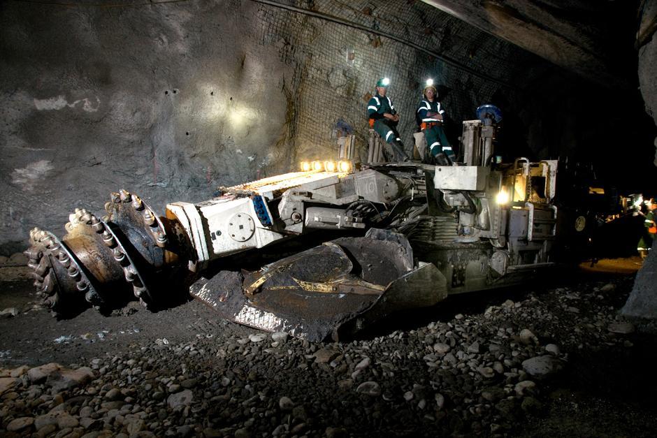
Hard rock tunnelling stands as one of the most challenging and unforgiving environments in modern civil engineering and heavy extraction logistics. Whether driving a deep subterranean transit network through urban granite formations or carving out access drifts in deep-pit mining operations, the mechanical and environmental stresses placed on equipment are extreme. At the center of these operations is the roadheader—a highly versatile excavation machine designed to cut through tough rock formations using a massive rotating cutter head mounted on an articulating boom. For these machines to maintain operational efficiency, they require a continuous supply of high-voltage electrical energy. This power must be delivered through a flexible trailing cable system that operates in the same harsh conditions as the machine itself.
In the close confines of an underground tunnel excavation, the primary power cable faces a continuous combination of physical abuse. It is exposed to intense vibrations from the cutter head grinding through solid rock, regular bending as the machine advances and adjusts its path, and potential impacts from falling rock shards. Furthermore, it must operate within tight spatial routing constraints that often force the cable to bend around narrow radii.
Because of these extreme demands, selecting an appropriate cable is a critical decision that directly impacts operational uptime and site safety. If an underspecified cable fails, it does not simply require a quick patch; it brings the entire excavation sequence to a sudden halt, stranding downstream hauling crews, delaying concrete lining schedules, and causing significant financial losses.
This buying guide serves as a practical, comprehensive resource for electrical engineers, procurement managers, and maintenance teams tasked with selecting and maintaining power cables for roadheaders operating in hard rock tunnelling projects. It moves beyond generic marketing claims to focus on the mechanical engineering principles, material science factors, and electrical performance parameters that define a truly resilient tunnel cable system.
By analyzing the specific operating patterns of roadheader machinery and matching them against verified engineering specifications—such as those found in Feichun's VDE-certified heavy-duty rubber cable lines—operators can transform their power infrastructure from a frequent failure point into a reliable, long-term asset.
2. What a Roadheader Includes
To correctly specify an electrical trailing cable for a roadheader, one must first understand the machine's internal mechanical architecture and electrical subsystems. A roadheader is not a static piece of industrial machinery; it is a complex, self-propelled excavation platform comprised of several high-power subsystems operating simultaneously within a compact steel chassis.
The Rotating Cutting Head
The primary tool of the roadheader is its cutting head, a large steel drum fitted with dozens of heavy-duty tungsten carbide picks. This head is mounted on a powerful telescoping boom that swings across the rock face, cutting away material through sheer mechanical force. The electric motors driving this cutting head are the largest consumers of electrical power on the machine, frequently requiring medium-voltage inputs (ranging from 1 kV up to 3.3 kV or 6.6 kV) to generate the massive torque needed to fracture hard rock. This high power demand requires a cable with substantial current-carrying capacity that remains light and flexible enough to move with the machine.
The Material Gathering and Conveyor System
Directly beneath the cutting boom sits the gathering apron, which uses rotating spinner arms or gathering claws to sweep loose rock debris onto an internal chain conveyor. The conveyor runs through the center of the machine, transporting tons of abrasive rock fragments backward to dump them onto secondary transport systems or haul vehicles. The electric motors and mechanical links driving this conveyor operate continuously alongside the cutting head, adding to the total electrical load and creating a constant stream of low-frequency structural vibrations throughout the entire chassis.
The High-Pressure Hydraulic System
While the cutting head and conveyors rely primarily on direct electric drives, the movement of the articulating boom, the positioning of the stabilization jacks, and the operation of the crawler tracks are driven by a high-pressure hydraulic system. This system uses electric-motor-driven hydraulic pumps to maintain pressures exceeding 250 bar. These hydraulic lines run parallel to the primary electrical distribution paths, exposing internal cables to elevated ambient operating temperatures and potential contact with hot hydraulic fluids or greases.
The Master Electric Drive Motors
All of these subsystems depend on the main electric motors housed within the roadheader's reinforced body. These motors require a stable, uncorrupted supply of clean power to prevent voltage sags, overheating, and insulation breakdown.
Because the trailing cable is attached directly to the rear of the machine, it does not simply sit alongside the equipment; it travels with it. As the roadheader advances, retreats, or maneuvers within the narrow tunnel face, the cable is subjected to continuous pulling tension, bending cycles, and structural vibrations. This close connection between machine motion and cable durability means that a failure in the cable jacket or internal copper conductors will immediately disable the entire machine.
3. Working Environment
The environmental conditions at a hard rock tunnel face represent a challenging combination of natural geological hazards and machine-driven mechanical abuse. An electrical cable operating in this space must maintain absolute dielectric and structural performance while facing multiple environmental hazards simultaneously.
Continuous High-Frequency Structural Vibrations
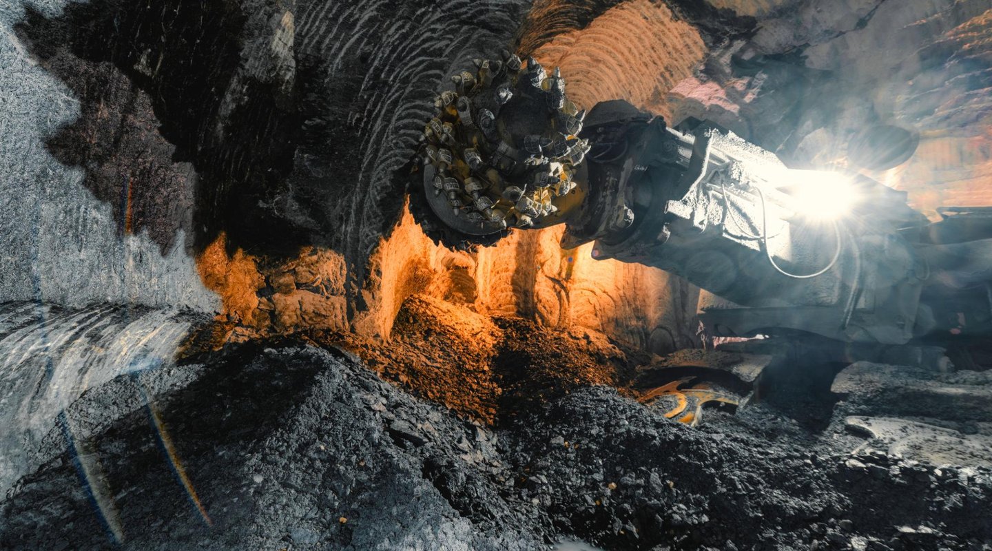
When the rotating cutting head strikes a hard rock face—such as granite, quartzite, or dense basalt—it generates massive impact forces. These forces are transmitted back through the cutter boom and chassis as high-frequency structural vibrations. These continuous shock waves travel directly down the trailing cable connection point.
Over time, this persistent vibration causes micro-stretching within standard cable jackets and leads to work-hardening of internal copper conductors. If the cable is not engineered specifically to absorb and dampen these high-frequency forces, the internal copper wires will experience rapid fatigue, resulting in broken strands and localized overheating.
Repeated Flexing and Torsional Stress During Machine Advance
A roadheader does not cut in a straight, uninterrupted line. It advances a few meters, backs up to allow structural steel arch installation, maneuvers laterally to widen the tunnel profile, and repositions to clear fallen debris.
This operational pattern means the trailing power cable is in a state of constant motion. It is continuously reeled off and spooled back onto motorized drums, fed through guiding rollers, and dragged across the tunnel floor. This movement subjects the cable to regular flexing and axial twisting, which can lead to structural deformation if the cable lacks adequate internal mechanical reinforcement.
Restricted Bending Radii in Confined Subterranean Spaces
Space inside an underground tunnel is extremely limited. The roadheader must share the narrow floor with ventilation ducting, water drainage pipes, scaling machines, and rock-bolt drills.
Because of these tight spatial constraints, trailing cables cannot be laid out in long, sweeping curves. Instead, they are often forced through sharp turns around structural ribs or fed through tight guide shoes mounted on the machine's chassis. Forcing a cable into a bend tighter than its intended engineering rating places severe stress on the outer sheath and insulation, accelerating the risk of a core-to-shield short circuit.
Direct Ground Contact with Abrasive, Fractured Debris
The floor of an active tunnel excavation is covered in sharp rock fragments, quartz dust, and spilled drilling water. Trailing cables are regularly dragged directly over these abrasive surfaces under heavy tension.
The rough, blasted rock acts like coarse sandpaper against the cable jacket. Additionally, the cable faces the constant risk of being stepped on by tracking equipment or struck by falling rock shards from unlined tunnel ceilings, requiring an outer sheath with exceptional impact and tear resistance.
Moisture Accumulation and Corrosive Dust Exposure
Underground works are naturally damp, humid environments. Groundwater often enters through the tunnel face, mixing with airborne silica dust and concrete curing agents to create a highly corrosive mud that coats all equipment.
The trailing cable must operate continuously while covered in this abrasive slurry. The outer jacket must provide a completely water-resistant barrier to prevent this mineralized moisture from reaching the internal electrical insulation, where it could cause premature grounding faults.
4. Why Cable Choice Matters
In heavy industrial project management, procurement teams are sometimes tempted to prioritize electrical specifications over mechanical durability when selecting cables. However, in hard rock tunnelling projects, this approach often leads to premature field failures. Experience shows that roadheader cable failures rarely begin as pure electrical overloads; instead, they almost always start as mechanical damage that eventually leads to an electrical failure.
The Path to Mechanical Degradation
When an underspecified or non-certified cable is deployed on a roadheader, its structural layers begin to degrade almost immediately under daily operational stresses. If the outer jacket compound lacks sufficient resilience, the friction from being dragged over blasted rock will gradually wear away the protective wall.
As the jacket thins, the cable loses its ability to protect the inner components from impacts. When the machine moves or winds the cable onto a reel, the internal phase conductors are subjected to excessive compression and bending stresses, causing the insulation to deform and thinned over time.
The Ingress of Moisture and Contaminants
Once the outer jacket suffers a minor cut or tear from a sharp stone, the cable's environmental protection is compromised. The high ambient humidity and hydrostatic pressure within the tunnel force mineralized water into the cable body.
Using capillary action, this moisture travels along the internal strands, causing rapid oxidation of unpolished copper wires. This oxidation increases electrical resistance, generating localized heat spots that melt adjacent insulation from the inside out until the cable experiences a major phase-to-earth electrical fault.
The True Cost of Excavation Downtime
In modern civil engineering projects, the execution schedule is a tightly integrated sequence of dependent tasks. The roadheader must excavate a section before the scaling crew can clear loose rock, the bolting team can install structural supports, and the shotcrete crew can apply the primary concrete lining.
If the roadheader loses power due to a cable failure, this entire sequence grinds to an immediate halt.
The financial losses from an idle tunnel project accumulate rapidly. Field labor crews remain on the payroll while standing idle, expensive heavy machinery sits unused, and concrete trucks may have to dump their loads if the delay lasts too long.
Furthermore, replacing a damaged trailing cable in a dark, confined underground space is a difficult and time-consuming process that requires specialized electrical technicians. By investing in a high-grade, verified cable engineered specifically for roadheader service, project managers can protect their excavation schedules and significantly reduce maintenance overheads.
5. Mechanical Performance Requirements
To select a roadheader cable that will deliver a long service life, engineers must look past basic product descriptions and evaluate three core mechanical performance factors: minimum bending radius, tensile strength, and flex life. These parameters define the physical boundaries within which the cable can operate safely without suffering structural damage.
Minimum Bending Radius
The minimum bending radius is the tightest curve a cable can safely form without causing structural damage to its internal components. This parameter is expressed as a multiple of the cable's total outer diameter (D).
Cables have two distinct bending radius limits: a larger radius for dynamic service where the cable is actively moving or spooled on reels, and a tighter radius for fixed installations where the cable remains static.
Respecting these limits during design and operation is critical; forcing a cable into a turn tighter than its engineering rating compresses the inner insulation, shifts the conductors out of geometric alignment, and accelerates material fatigue.
Tensile Strength
Tensile strength measures the maximum linear pulling force a cable can tolerate along its longitudinal axis without stretching the internal copper cores. This value is measured in Newtons (N) and is a critical metric for trailing cables that are regularly pulled behind heavy tracking equipment or wound onto high-torque motorized reels.
If the pulling force exceeds the cable's structural capacity, the copper conductors will experience permanent elongation. This stretching thins the wire cross-section, increasing electrical resistance and leading to dangerous operational overheating.
Operational Flex Life
Flex life defines the total number of bending and unbending cycles a cable can complete before its structural components suffer mechanical failure. For roadheader applications, a suitable cable must be rated to survive millions of bending cycles under load.
Achieving a high flex life requires careful integration of fine-stranded conductors, flexible insulation materials, and robust outer sheaths. Selecting a cable based on its ability to handle continuous dynamic movement, rather than occasional shifting, is essential for ensuring long-term reliability at the tunnel face.
6. Bending Radius Guidance
The bending radius specification is a critical parameter when selecting cables for mobile underground machinery. In the confined layout of a roadheader's rear chassis and spooling system, cables are continuously guided through sharp turns, making this parameter a frequent focus during engineering reviews.
The Engineering Math Behind the Multipliers
To understand why these bending limits matter, consider a heavy-duty power cable with a total outer diameter (D) of 50 millimeters. If the manufacturer's datasheet specifies a minimum bending radius of 6xD for fixed installation, the cable can be safely installed in static trays with a curve radius of 300 millimeters.
However, when that same cable is used in dynamic service—such as being wound onto a motorized drum or guided through moving articulation joints—the standard recommendation expands to a more conservative 10xD. This means the guide rollers and spooling drum cores must feature a minimum radius of 500 millimeters (a total diameter of 1000 millimeters) to protect the moving cable.
The Consequences of Tight Spatial Routing
Forcing a cable to bend past its engineered limits triggers a destructive mechanical process inside the jacket. On the outside edge of the turn, the outer jacket and insulation are subjected to severe tensile stretching, causing the polymer chains to thin and develop micro-cracks. On the inside edge, the materials face intense compression, forcing the individual insulated cores against each other.
This localized pressure can cause the soft insulation to deform and migrate away from the copper strands. Over time, this material migration thins the protective layer between phases, eventually leading to an explosive short circuit.
Therefore, verifying that all machine guide pulleys, reeling drums, and tunnel routing brackets match the cable's dynamic bending specifications is a fundamental step in preventing premature field failures.
7. Tensile Strength
When a roadheader maneuvers along an active tunnel face, it often drags several hundred meters of heavy trailing cable across the rough floor. The mechanical force required to pull this weight creates significant tensile load along the cable's length, making verified tensile strength a key performance metric for procurement teams.
The Physics of Pulling Loads
The total tensile load experienced by a trailing cable is determined by three main factors: the total weight of the cable length in service, the friction coefficient between the outer jacket and the rough tunnel floor, and the acceleration rate of the machine's crawler tracks.
In heavy-duty applications, this pulling force can quickly reach thousands of Newtons of continuous tension. If a cable relies solely on its copper conductors to handle this pulling force, it will suffer rapid damage. Copper is a ductile metal that stretches easily under tension.
When a copper strand stretches, its cross-sectional area shrinks, which increases its electrical resistance. This higher resistance causes the conductor to generate excessive heat under normal operating currents, accelerating insulation aging and increasing the risk of thermal failure.
Integrated Tensile Reinforcement
To protect the internal copper cores from these pulling forces, heavy-duty roadheader cables incorporate specialized tensile reinforcement layers within their sheathing systems. Advanced designs feature a high-tensile polyester or aramid fiber anti-torsion braid integrated between the inner and outer sheaths.
This structural braid acts as an internal strength member, absorbing the linear pulling forces and transferring them evenly across the jacket rather than letting them reach the sensitive copper conductors.
When specifying a cable for long trailing runs, buyers should verify the maximum tensile load rating in Newtons (N) on the manufacturer's datasheet, rather than relying on the cable's visual thickness as an indicator of strength.
8. Flex Life
Flex life measures a cable's ability to maintain electrical and structural performance while undergoing continuous mechanical movement. For a trailing cable attached to a roadheader's articulating boom or automated spooling reel, handling constant motion is a fundamental requirement of daily service.
Understanding the Bending Cycle Benchmark
In cable engineering, a single flex cycle consists of bending a straight cable sample to its minimum dynamic radius, straightening it, bending it in the opposite direction, and straightening it again.
Standard industrial utility cables are typically rated to handle only a few thousand of these cycles before their jackets begin to crack. In contrast, heavy-duty mining and tunnel cables are engineered to survive millions of bending cycles under continuous mechanical load.
This exceptional endurance is achieved through careful material selection and structural layout. The conductors use Class 5 fine-stranded configurations, where thousands of tiny, precision-drawn copper wires are bundled together to distribute bending stresses evenly across a large surface area.
The primary insulation and sheathing layers use advanced elastomeric compounds that retain their flexibility over a broad temperature range, ensuring the cable can bend smoothly without developing surface cracks or internal structural separation.
Dynamic Movement vs. Occasional Flexing
When evaluating options, engineers must distinguish between cables designed for occasional shifting and those built for continuous dynamic service. A cable rated only for occasional movement will quickly fail if subjected to the high-frequency vibrations and constant spooling cycles of an active roadheader.
Specifying a high-flex-life cable ensures the electrical distribution system can handle the machine's continuous adjustments, keeping operations moving forward without unexpected interruptions.
9. Common Selection Errors
Analyzing common cable selection errors in underground construction projects provides valuable insights into the specific performance features required for reliable tunnel service. When field failures occur, they can usually be traced back to a mismatch between the chosen cable material and the actual mechanical demands of the job site.
Error 1: Selecting PVC Sheathed Cables for Roadheader Trailing Duty
One of the most frequent errors in procurement is choosing a cable with a standard Polyvinyl Chloride (PVC) outer jacket to save on initial costs. While PVC performs well in static indoor installations, it lacks the elasticity and toughness required for dynamic underground service.
When dragged over sharp rock shards or subjected to continuous vibration, PVC jackets quickly develop micro-notches that expand into deep cracks. Furthermore, PVC becomes stiff and brittle in cooler tunnel temperatures, making it highly susceptible to shattering under sudden physical impacts.
Error 2: Operating Cables Past Their Minimum Dynamic Bending Radius
Even high-quality rubber cables will fail prematurely if forced through turns tighter than their engineering specifications allow. This error often occurs when space constraints lead to the installation of undersized guide pulleys or tight routing brackets on the machine's chassis.
Operating a cable past its bending limit subjects the internal components to extreme compression and tension, causing the insulation to deform and leading to rapid conductor fatigue.
Error 3: Choosing an Inappropriate Insulation Voltage Class
Selecting a cable without verifying the electrical system's specific voltage requirements creates a severe safety hazard. For example, using a standard low-voltage cable on a machine that requires a medium-voltage feed (such as 3.3 kV or 6.6 kV) will lead to immediate insulation breakdown.
Medium-voltage applications require specialized cables with integrated semi-conductive layers and individual phase screening to contain high-voltage fields safely and prevent dangerous surface tracking.
Error 4: Underestimating High-Frequency Vibration and Shock Waves
Using a cable with rigid Class 1 solid or Class 2 coarse-stranded conductors on a roadheader cutting boom is a guaranteed path to early failure. The continuous shock waves generated by the cutting head grinding through hard rock will cause rigid copper wires to work-harden and snap within days.
Roadheader service requires highly flexible Class 5 fine-stranded conductors that can absorb these continuous vibrations without suffering material fatigue.
10. Cable Features to Match
To simplify the selection process, engineering teams can use a practical decision checklist to match specific roadheader operating challenges with the corresponding cable performance features. This approach ensures every structural layer of the chosen cable is optimized for the actual demands of the tunnel environment.
Flexible Conductor for Vibration: The core conductors must utilize Class 5 fine-stranded copper wires to absorb the continuous, high-frequency structural vibrations generated by the cutting head without experiencing work-hardening or broken strands.
Low Bending Radius for Sharp Routing: The cable architecture must support a low dynamic bending radius (down to 5 times the overall diameter for premium rubber families) to allow for safe, compact routing through the machine's tight internal spaces and guide rollers.
Heavy Rubber Sheath for Rock Impact: The outer sheathing must feature a heavy-duty, cross-linked rubber compound (like Type 5GM5) or a rugged polyurethane layer to cushion internal components against sharp rock impacts and prevent notch propagation from ground friction.
Water-Resistant Jacket for Moisture: The outer jacket must provide a completely water-resistant and chemical-resistant barrier to isolate the internal insulation from corrosive mud, groundwater ingress, and spilled hydraulic fluids.
Copper Conductor for Current-Carrying Performance: The internal conductors should utilize premium tinned copper strands to deliver stable current-carrying capacity while providing long-term protection against chemical corrosion and wire oxidation.
11. How to Select the Right Cable
Selecting the ideal cable for a roadheader project requires a systematic approach that evaluates both electrical loads and mechanical stresses in a structured sequence. By following this step-by-step framework, engineers can ensure the final cable specification matches the true operational demands of their specific tunnel environment.
Step 1: Verify the System's Core Electrical Requirements
The selection process begins by confirming the machine's nominal operating voltage and total current load under peak conditions. For low-voltage setups (up to 1 kV), a heavy-duty flexible rubber power cable like the Feichun NSSHÖU family provides an excellent foundation.
If the roadheader runs on a medium-voltage supply (such as 3.3 kV, 6.6 kV, or 11 kV), engineers must transition to a shielded mining cable class like the Feichun NTSCGEWÖU family, which incorporates individual phase screening and semi-conductive layers to handle higher voltage fields safely.
Step 2: Assess the Dynamic Motion Profile and Spatial Routing Constraints
Next, analyze how the cable will move during daily operations. Measure the diameter of the machine's motorized spooling drums, guide pulleys, and routing channels to determine the minimum dynamic bending radius required.
If the space is extremely tight, choose a high-performance cable family engineered for low bending multipliers to prevent excessive stress on the internal insulation layers during machine adjustments.
Step 3: Evaluate Ground Hazards and Environmental Exposure
Examine the specific geological conditions along the tunnel floor. If the environment is filled with sharp fractured rock, quartz dust, and standing groundwater, the cable requires an outer jacket with exceptional tear resistance and certified water submersibility.
Verify that the sheathing material provides complete protection against moisture ingress and common site chemicals like oils and hydraulic greases.
Step 4: Confirm Mechanical Load Capacities and Flex-Life Expectations
Calculate the maximum pulling forces the cable will experience when dragged behind the machine or wound onto high-torque reels. Ensure the chosen model features integrated tensile reinforcement, such as an internal anti-torsion braid, to handle these linear loads without stretching the copper cores.
Finally, review the manufacturer's flex-life data to confirm the cable is rated to survive millions of dynamic bending cycles under continuous load.
12. Why Hard Rock Is Different
Tunnelling through hard rock formations—such as granite, gneiss, quartzite, or dense basalt—presents a significantly higher level of mechanical stress than working in softer ground conditions like shale, clay, or soft sandstone. This geological difference has a direct impact on the survival rate of underground electrical infrastructure.
The Impact of High-Amplitude Structural Shock Waves
When a roadheader cuts through hard rock, the machine picks cannot easily penetrate the surface. Instead, they must grind away the material through sheer mechanical impact. This process generates intense, high-amplitude structural shock waves that travel back through the entire machine chassis and into the trailing cable connection.
In softer ground, the surrounding soil acts as a natural dampener, absorbing much of the kinetic energy. In hard rock, however, these raw vibrations pass directly into the cable body.
Without a highly flexible conductor system composed of fine-stranded Class 5 copper wires, this persistent shaking will rapidly work-harden the metal, causing individual strands to snap and leading to localized overheating.
The Threat of Razor-Sharp Fractured Debris
Hard rock fractures into sharp, jagged shards with razor-like edges. As the roadheader advances, the trailing cable is dragged directly over these sharp fragments under heavy tension.
Standard general-purpose mining cables lack the jacket toughness required to survive this continuous cutting action; their sheaths quickly develop deep notches that split open under mechanical stress.
Hard rock tunnelling requires a premium outer jacket compound—such as heavy-duty cross-linked rubber or rugged polyurethane—that can resist cutting and prevent surface scratches from expanding into large tears. By specifying a cable built for these exact conditions, operators can ensure their power networks deliver reliable performance throughout the excavation cycle.
13. Selection Summary
To ensure a reliable and successful selection process, engineering teams can use this clear, sentence-based summary guide to match specific roadheader operational challenges with the correct cable specifications:
For vibration, choose a flexible conductor: To absorb continuous structural vibrations from the cutting head, always specify a cable featuring Class 5 fine-stranded tinned copper conductors.
For sharp bending, choose a low-bend-radius design: To ensure safe installation through tight machine guide rollers and narrow tunnel spaces, select a cable engineered for a low minimum dynamic bending radius (down to 5 times the overall diameter).
For rock impact, choose a heavy rubber sheath: To protect internal components against sharp, fractured rock shards and high ground friction, choose a cable with a heavy-duty, cross-linked rubber sheath (Type 5GM5) or a rugged polyurethane jacket.
For moisture, choose a water-resistant jacket: To prevent groundwater and corrosive mud from entering the cable body, verify the outer jacket provides complete water-resistance and certified long-term submersibility.
For high current, choose a properly sized copper conductor: To deliver stable, high-amperage power transmission with minimal line drops under peak loads, ensure the copper conductors are sized conservatively and utilize premium tinned wire bundles.
14. Conclusion
Selecting the right power cable for a roadheader operating in hard rock tunnelling projects is a critical decision that requires balancing electrical capacity with mechanical durability. A trailing cable cannot function simply as a passive electrical line; it must serve as a highly engineered structural component capable of moving with the machine while resisting severe environmental abuse. Procurement choices based purely on initial cost savings often lead to premature failures, resulting in expensive project downtime, disrupted excavation schedules, and increased workplace safety risks.
By prioritizing verified mechanical performance factors—including strict dynamic bending limits, high tensile strength, and exceptional flex life—engineering teams can select an electrical infrastructure that matches the power and resilience of their heavy excavation machinery. Deploying high-quality, VDE-certified cables like Feichun's heavy-duty rubber power lines gives operators the confidence that their critical systems will perform reliably under the region's intense physical demands.
Ultimately, investing in a rugged, application-specific cable design is a proactive step that protects your project timeline, reduces maintenance costs, and ensures a safe, efficient underground operation from the initial cut to the final tunnel lining.
Port crane cables | Mining cables | Reeling cables | Trailing cables | Festoon cables | Heavy-duty power cables | Medium voltage cables | Offshore crane cables | Underground mining cables | Dragline cables | Shearer cables | Container handling cables | STS crane cables | RTG cables | Mobile equipment cables | Armored cables | Flexible power cables | VFD cables | Submersible cables | Cold resistant cables | Abrasion resistant cables | Flame retardant cables | Marine environment cables | Opencast mining | Underground operations
© 2006 All rights reserved.
[INDUSTRIAL_CABLES]
INDUSTRIAL GRADE CABLE SYSTEMS | PORT & MINING SOLUTIONS
TEL: +86 153 7530 2641 |MAIL: hongjing.Wang@feichuncables.com