
The Definitive Guide to Crane Cable Bending Radius: Engineering Calculations, Standards, and Prevention of Premature Failures
Learn how to calculate minimum bending radius for crane, festoon and reeling cables using simple ×D formulas, DIN VDE/IEC guidance and real NSHTÖU examples to avoid premature cable failure.
hongjing.Wang@Feichun
7/17/202619 min read
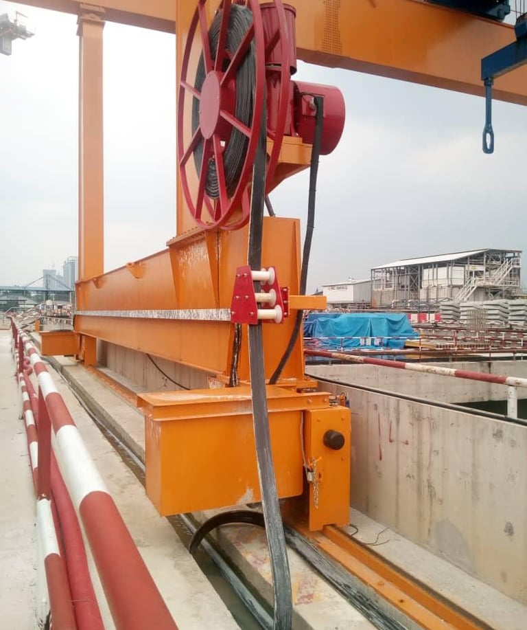
In heavy industrial operations, the durability and reliability of electrical infrastructure are the backbones of continuous productivity. Whether operating automated container cranes at major maritime hubs in the Middle East, high-capacity overhead traveling cranes in heavy manufacturing plants, or bucket-wheel reclaimers in deep-pit mining environments, the integrity of flexible power and control cables is paramount. Despite their robust designs, these dynamic lifelines are highly sensitive to physical configuration. Among all design parameters, the minimum bending radius of a cable stands out as the single most critical geometric constraint determining operational longevity. Ignoring or miscalculating this parameter is the leading cause of premature mechanical failure, conductor fatigue, sheath splitting, and catastrophic electrical short circuits.
1. Search Intent and Article Positioning
This technical guide is written specifically for electrical designers, procurement engineers, maintenance managers, and site technicians who search for precise instructions regarding "crane cable minimum bending radius", "reeling cable bend radius calculation", and "flexible cable bending radius". When field engineers and design offices search for these terms, they are typically looking for more than just a simple lookup factor. They require a rigorous, mathematically sound, and practically field-tested framework to ensure that the physical routing, pulley sizes, festoon trolley depths, and drum diameters they specify will protect their technical assets.
Our goal is to position this comprehensive manual as the primary educational and engineering resource for flexible cable selection and installation. Rather than discussing generic building wire or standard residential cables, our focus remains strictly on heavy-duty, rubber-sheathed flexible crane cables designed for high mechanical stresses, continuous movement, and challenging environmental conditions. By understanding the mechanical limits of materials and the mathematical relationships behind bending stresses, engineering teams can make informed pre-purchase decisions, eliminate premature structural degradation, and safeguard their systems against costly unplanned downtime.
2. What Is Cable Bend Radius?
In the physical and structural analysis of electrical conductors, the bending radius is defined as the radius of the inner curve that the cable can be safely curved or wrapped around without experiencing mechanical strain, permanent material deformation, or loss of electrical insulation integrity. When a cylindrical cable structure is forced into a curved profile, two distinct stress zones are created across its cross-section. The outer side of the bend experiences high tensile stress, stretching the copper strands, insulation, and outer protective sheathing. Conversely, the inner side of the bend experiences heavy compressive stress, forcing the materials to bunch together.
The minimum bending radius is the absolute lower limit of this geometric curve, which is mathematically represented as a direct scalar multiple of the cable's overall finished external diameter, represented by the variable D. For example, a recommended minimum bending radius of 6 × D means that the radius of the bend, measured from the center of the curve to the innermost surface of the cable, must never be less than 6 times the complete external diameter of the cable including all jackets and sheaths.
It is vital for design engineers to distinguish between two key operational concepts:
Fixed Installation Radius: This is the static bending radius permitted when a flexible cable is installed in a permanent, non-moving configuration. In this scenario, the cable is bent once during initial installation and remains clamped or anchored in place for its entire service life. Because the cable is not subjected to repetitive cycles of fatigue, the materials can safely tolerate a tighter bend.
Dynamic Bending Radius: This is the operational bending radius required for cables that are in continuous, cyclical, or frequent motion. Such applications include motorized reeling drums, active festoon systems, drag chains, or vertical hoist assemblies. In these systems, thousands or even millions of bending cycles occur, compounding internal friction and structural fatigue. Consequently, the dynamic bending radius must be significantly larger than the static radius to accommodate these active mechanical stresses.
3. Why Minimum Bending Radius Matters for Crane Cables
In heavy industry, cables are treated as structural machinery, not merely static electrical conductors. When a crane cable is forced to bend past its engineered limit, several destructive physical processes begin within its cross-section. At the core, the fine copper strands that make up the flexible conductors are subjected to massive structural shear forces. Over time, this localized stress leads to work-hardening of the copper, making it brittle. Individual strands begin to fracture, reducing the effective cross-sectional area of the conductor. As the cross-section decreases, the electrical resistance of the cable rises, generating excessive heat (known as Joule heating) and eventually leading to localized copper melting, insulation failure, and catastrophic short circuits.
Simultaneously, the physical layers of insulation surrounding the copper conductors are compressed on the inner curve and stretched thin on the outer curve. This physical distortion directly reduces the dielectric strength of the insulation material. In high-stress systems like vertical reels or high-speed festoons, these internal forces cause the conductors to migrate through the rubber compounds, sometimes pressing directly against each other or through the outer sheath. The outer protective rubber sheath, which is formulated to resist environmental degradation, UV exposure, and moisture, will develop micro-cracks under severe tension. In dry, high-temperature regions like the Middle East, where ambient temperatures can routinely exceed 50 ℃ and direct sunlight heats sheaths to over 80 ℃, these micro-cracks quickly expand into deep splits, allowing moisture, dust, and corrosive industrial chemicals to penetrate the core.
Beyond the immediate physical damage, ignoring manufacturer-specified bending radii carries severe operational, financial, and legal consequences. Standard warranties offered by premium manufacturers like Feichun are strictly contingent upon the system being engineered and operated within defined physical parameters. If a forensic analysis of a failed cable reveals that the operational sheave, drum, or loop radius was smaller than the mandatory minimum limits, the warranty is immediately voided. Furthermore, international safety regulations, including IEC standards and regional engineering codes, mandate strict compliance with these bending limits to protect personnel from explosive electrical faults and mechanical crane structural failures.
4. Basic Bend Radius Formula and Key Variables
To ensure precise engineering during the design phase of crane systems, engineers rely on a fundamental geometric relationship to establish safe layout boundaries. The standard minimum bending radius is calculated using the following formula:
R_min = k × D
Where the variables are defined as follows:
R_min is the minimum allowable bending radius, measured in millimeters, from the center point of the curvature to the inner surface of the cable.
D represents the finished overall external diameter of the cable, measured in millimeters. It is critical to emphasize that this value represents the complete outer boundary of the external protective sheath, not the diameter of the internal copper conductor or the insulated core. This value must always be obtained from the official datasheet provided by Feichun.
k is a dimensionless multiplier factor determined by the structural construction of the cable, the materials used in its core and sheaths, and the specific dynamic nature of the physical application. This factor is derived from empirical laboratory fatigue testing and international standards like DIN VDE 0298-3.
To illustrate this formula with a clear, practical numerical example: Let us consider a high-performance Feichun flexible reeling cable with an overall finished outer diameter of 50 mm. The cable is slated for installation on a motorized drum system with a recommended dynamic bending factor of 10 × D. Applying the formula, the calculation is:
R_min = 10 × 50 mm = 500 mm
This simple calculation indicates that the absolute smallest radius of any curve, sheave, guide roller, or drum core that this cable encounters during operation must be at least 500 mm. Consequently, the minimum drum core diameter would be twice this value, representing a minimum physical diameter of 1000 mm (or 1 meter).
5. Typical Bend Radius Rules for Fixed vs Flexible Cables
The structural difference between a static power distribution cable and a dynamic, flexible crane cable is vast. Fixed power cables, typically used for underground runs, cable trays, or structural conduit, are constructed with solid or coarsely stranded conductors and rigid protective armor layers (such as steel tape or steel wire armor). Because these cables are designed to be pulled into place once and never moved again, their bending radius requirements are relatively compact. International standards, such as IEC 60502, routinely permit minimum bending radii in the range of 4 × D to 6 × D for unarmoured cables in fixed, protected installations.
In contrast, flexible dynamic cables are engineered for constant articulation, winding, and reeling. Their internal construction utilizes highly flexible Class 5 or Class 6 fine-wired copper conductors, synthetic textile reinforcement elements (such as anti-torsion braids), and specialized synthetic rubber jackets. Because these materials must slide against one another internally during movement, the physical forces are much more dynamic. For these active applications, manufacturers and standards like DIN VDE 0298-3 enforce much larger bending factors. Depending on the mechanical load, velocity, and operating configuration, dynamic bending factors range from 7.5 × D up to 12 × D, and in high-tension or high-voltage vertical reeling systems, they can exceed 15 × D.
It is a critical design error to apply fixed-installation bending factors to dynamic crane applications. Doing so ignores the severe internal friction, heat generation, and mechanical wear that occurs when a moving cable is forced through a tight radius, resulting in rapid failure of the internal elements long before the anticipated service life of the system is reached.
6. Bend Radius Guidelines for Common Crane Cable Applications
6.1 Fixed and Static Power Runs on Cranes
Even on highly dynamic machinery like container cranes or bulk unloaders, there are many structural sections where cables are routed through static conduit, fixed cable trays, or permanent structural raceways. These include mast feeds, static connections between ground junction boxes and the crane base, or distribution lines inside the machinery house. For these stationary installations, flexible cables like Feichun's heavy-duty rubber-sheathed series can be configured with smaller bending radii. Under standard DIN VDE 0298-3 guidelines and Feichun specifications, a bending factor of 3 × D to 6 × D is generally permitted for fixed runs, depending on the outer diameter of the cable.
However, installation technicians must exercise extreme caution during the initial pull-in phase of the project. While the final resting state of the cable can safely accommodate a tight bend, the physical tension applied during the pulling process introduces severe temporary stresses. Most manufacturers, including Feichun, advise that during the actual pulling and routing of the cable, a minimum radius of 10 × D to 15 × D must be maintained to prevent internal core displacement or structural damage before the crane ever powers up.
6.2 Flexible Cables with Occasional Movement
Certain crane systems contain subsystems that undergo only occasional or slow-speed movements. Examples include crane cabin control leads, manual pendant stations, auxiliary maintenance winches, and temporary power connections used during inspection or repair. These applications fall under the "free movement" category defined in European and international standards. For cables subjected to free, non-forced movement without guided tension, the absolute minimum bending radius is typically rated at 3 × D to 5 × D for small-diameter cables.
In heavy industrial crane environments, however, raw theoretical limits should rarely be used. Mechanical shock, continuous structural vibrations, high wind loads, and severe temperature fluctuations demand a conservative safety margin. In practical field applications, engineering designers should specify a minimum bending radius of at least 8 × D to 10 × D. This additional margin ensures that unexpected physical impacts or rapid movements do not push the cable past its material yield points.
6.3 Festoon Cables on Gantry and Bridge Cranes
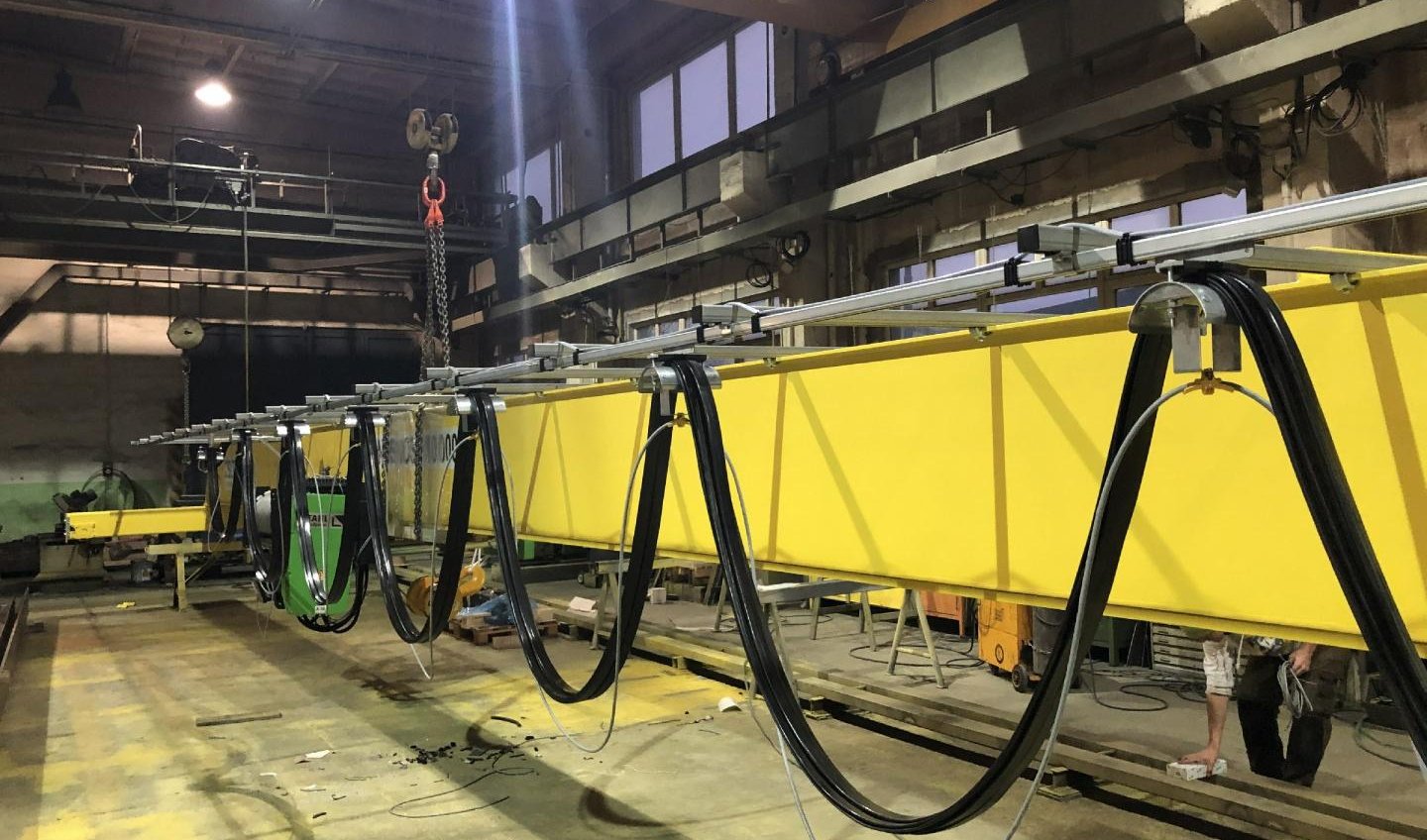
Festoon systems are highly dynamic setups where flat or round cables are suspended from mobile trolleys that travel along C-rails or I-beams. This setup is common on overhead bridge cranes, container gantry cranes, and rubber-tired gantry cranes (RTGs). As the trolley moves back and forth, the cables undergo repetitive bending as they loop and straighten. The key stress points in a festoon system are the saddle clamps where the cables are secured to the trolleys. At these points, the cable is bent over a rounded curved block, and the weight of the hanging loop pulls down on the bend.
While basic DIN VDE tables for cable trolley operations state an absolute minimum factor of 3 × D to 5 × D, real-world crane system designers should never design to this limit if they expect long-term reliability. To maximize cable lifetime under continuous operational cycling, a factor of 10 × D is widely recommended by crane engineering specialists. The physical layout of the festoon loop depth, the spacing between individual trolleys, the radius of the saddle clamps, and the environmental factors must be carefully co-designed. In region-specific installations, such as the hot coastal ports of the Middle East, high ambient temperatures soften rubber jackets, making proper geometric layout even more crucial to prevent stretching and kinking under high-velocity movements.
6.4 Reeling and Drum Cables (Vertical and Horizontal)
Motorized cable reels are among the most demanding mechanical environments a flexible cable can face. Reeling systems, found on massive Ship-to-Shore (STS) container cranes, stacker-reclaimers, and automated stacking cranes (ASCs), subject the cable to continuous winding and unwinding under high mechanical tension. These systems can be configured horizontally along a ground track or vertically where the cable supports its own suspended weight as it reels up and down on a gantry structure.
For drum operations, DIN VDE 0298-3 lists minimum bending factors of 5 × D to 6 × D. However, these baseline values are only suitable for low-speed, light-duty applications. For heavy-duty industrial and port crane operations, Feichun and other leading manufacturers recommend a much more conservative factor of 10 × D to 15 × D. In high-speed reeling applications where velocities exceed 100 meters per minute and acceleration rates are high, using a factor of 12 × D to 15 × D for the drum core diameter is standard practice. A larger drum core reduces the curvature angle, which directly minimizes the internal shear stress on the conductors, limits heat build-up from continuous flexing, and extends the overall mechanical life of the cable by several hundred percent.
7. Overview of Relevant Standards and Guidance
7.1 DIN VDE 0298-3
DIN VDE 0298-3 is the premier international standard governing the application, selection, and installation of low-voltage flexible cables up to 0.6/1 kV. It provides comprehensive technical tables detailing the minimum permissible bending radii for flexible cables based on their diameter, construction, and specific dynamic application. The standard classifies operations into clear functional categories, including:
Cables for fixed installation in structural runs
Flexible cables used in fixed installations
Cables in free-movement configurations
Cables operating on motorized and gravity-fed drums
Cables in active festoon trolley assemblies
Cables installed in continuous drag chain systems
Cables operating over roller deviation systems and guide pulleys
The standard establishes that the multiplier factor k is not static; it scales based on the outer diameter range of the cable. For example, a cable with an outer diameter up to 8 mm may have a smaller multiplier, whereas larger cables (8 to 12 mm, 12 to 20 mm, and above 20 mm) require progressively larger multipliers to compensate for the increased bulk and resistance to bending inherent in thicker cross-sections.
7.2 IEC 60227 for PVC Insulated Flexible Cables
IEC 60227 is a widely referenced international standard that covers polyvinyl chloride (PVC) insulated flexible cables rated up to 450/750 V. This standard is commonly used for general-purpose utility wiring, basic control lines, and light-duty commercial flexible cords. For fixed installations, IEC 60227 typically specifies a minimum bending radius of 4 × D for cables with an outer diameter less than or equal to 25 mm, and 6 × D for cables exceeding this threshold.
However, for heavy-duty crane, port, and mining applications, PVC-insulated cables under IEC 60227 are generally unsuitable. PVC material is prone to hardening and cracking at lower temperatures, and it becomes excessively soft and mechanically weak under high ambient temperatures (such as those encountered in Middle Eastern summers). Furthermore, PVC lacks the high tensile strength and elastic memory required for continuous high-speed reeling or festoon operations. Designers should restrict the use of IEC 60227 cables to static, indoor, or auxiliary control panels and always specify heavy-duty rubber-jacketed cables for dynamic crane systems.
7.3 IEC 60502 for Power Cables
IEC 60502 governs the construction, testing, and installation of extruded solid insulated power cables rated from 1 kV up to 30 kV. This standard is highly relevant for the main medium-voltage (MV) feeder lines that supply electrical power to cranes from the primary port substations. Because these feeder lines are either buried, installed in concrete trenches, or mounted along static structural trays, they utilize robust unarmoured or steel-wire/tape armoured designs.
Under IEC 60502, the recommended minimum bending radii for static installation are as follows:
For single-core unarmoured cables: 15 × D
For multi-core unarmoured cables: 12 × D
For single-core armoured cables: 15 × D
For multi-core armoured cables: 12 × D up to 15 × D depending on the specific construction and voltage rating
While these values are designed for static power transmission lines, they provide essential geometric boundaries for routing the high-voltage supply lines that feed crane systems.
8. Typical Manufacturer Recommendations for Crane and Reeling Cables
While international standards provide indispensable baseline guidelines, premium crane cable manufacturers often establish design parameters that are more conservative to ensure absolute reliability in harsh operational environments. Feichun, as a leading global designer of high-performance rubber-sheathed crane and trailing cables, conducts rigorous, real-world dynamic lifecycle testing in its laboratories to determine exact material fatigue limits.
For specialized rubber-sheathed trailing and reeling cables (such as the NSHTÖU family), Feichun's engineering datasheets often specify a multi-tiered bending radius guideline that corresponds to the specific installation method:
Fixed Static Installation: 4 × D to 6 × D, allowing compact routing in stationary junction boxes and structural frames.
Freely Moved / Dynamic Movement: 10 × D, providing a robust buffer against physical vibration and high-velocity acceleration.
Forced Guidance / Drum Operation: 12 × D to 15 × D, engineered to withstand the severe tensile, torsional, and bending loads experienced during high-speed reeling on motorized drums.
When there is a discrepancy between a generic standard and the specific datasheet provided by Feichun, engineering designers must always adhere to the stricter, more conservative value to guarantee system safety and maintain warranty coverage.
9. Example: NSHTÖU Crane and Reeling Cables
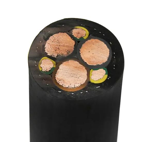
The (N)SHTÖU rubber-sheathed trailing and reeling cable is the global industry standard for low-voltage power and control delivery in heavy machinery, container cranes, mining hoists, and material handling conveyors. Feichun's premium NSHTÖU cables are specifically engineered for high mechanical stresses and continuous reeling operations. The core design features ultra-fine tinned copper conductors insulated with high-grade rubber compound, wrapped in an anti-torsion textile support braid integrated into the heavy-duty synthetic rubber outer sheath.
According to Feichun's technical data sheet for NSHTÖU cables, the minimum bending radius is strictly defined as follows:
For flexible use with an outer diameter less than 21.5 mm: 5 × D
For flexible use with an outer diameter greater than 21.5 mm: 6.25 × D
To demonstrate the practical application of this data in a crane design scenario, let us evaluate a Feichun 4 G 50.0 NSHTÖU low-voltage power cable (consisting of 4 cores with a cross-sectional area of 50 mm² per conductor). Consulting the Feichun datasheet, we obtain the following technical parameters for this specific cable:
Outer Diameter (D): 40.6 mm
Copper Index: 1920 kg/km
Total Weight: 3220 kg/km
Since the overall outer diameter of 40.6 mm is greater than 21.5 mm, we must apply the bending multiplier of 6.25 × D. The calculation is as follows:
R_min = 6.25 × 40.6 mm = 253.75 mm
This result shows that the absolute minimum bending radius for this cable in a dynamic, flexible application is 253.75 mm. To ensure a professional safety margin, engineering design files would round this value up to 260 mm. Consequently, if this cable were used on a motorized reel, the minimum drum core diameter must be at least 520 mm. If the same cable is utilized in an aggressive, high-speed vertical hoist system, industry best practices recommend increasing the dynamic factor to 10 × D or 12 × D, yielding an optimal bending radius of 406 mm to 487 mm, which vastly increases the physical service life of the cable under continuous tension.
10. Other Common Reeling Cable Families
10.1 Feichun TROMMELFLEX NSHTÖU
The TROMMELFLEX NSHTÖU series represents Feichun's highly specialized line of drum-reeling cables designed for continuous reeling and unreeling on heavy-duty container cranes, stackers, reclaimers, and massive mobile conveyors. These cables are formulated with an exceptionally robust outer rubber compound that resists tear propagation, abrasion, and intense UV radiation. This makes them highly suitable for the demanding environmental conditions found in desert climates and industrial mining sites.
Feichun's TROMMELFLEX series incorporates a high-tensile internal textile braid that serves as an anti-torsion element, preventing the cable from twisting or forming "corkscrew" deformations under heavy loads. The typical bending radius recommendation for the TROMMELFLEX series in active reeling service is 7.5 × D to 10 × D. For high-velocity setups (exceeding 120 meters per minute) or vertical gravity-fed applications, Feichun recommends a conservative design factor of 12 × D to preserve core geometry and prevent physical degradation.
10.2 Feichun PROTOLON (SMK+HS)
For the most demanding mechanical and environmental conditions, such as high-capacity Ship-to-Shore cranes and deep-pit mining shovel operations, the Feichun PROTOLON (SMK+HS) series is the preferred choice. These cables are engineered to handle extreme mechanical loads, rapid acceleration, and high torsional stress. They feature a specialized dual-layer outer sheath with an embedded high-tensile aramid braid to provide maximum structural support.
Technical specifications for the PROTOLON series call for a highly conservative dynamic bending radius, typically in the range of 10 × D to 15 × D for continuous reeling service. While a tighter bend might be physically possible in a laboratory setting, field experience in high-throughput ports shows that maintaining a larger bending radius (e.g., 12 × D to 15 × D) on the motorized reel dramatically reduces internal friction and heat buildup. This simple geometric choice can double or triple the operational lifetime of the cable, ensuring uninterrupted crane operations.
10.3 Feichun (N)TSCGEWOEU Reeling and Drag Chain Cables
When operating medium-voltage (MV) systems rated from 6 kV up to 30 kV, engineers specify the Feichun (N)TSCGEWOEU series. These flexible, rubber-sheathed cables are designed for heavy-duty reeling, drag chains, and mobile power connections on massive mining excavators and port cranes. Because medium-voltage cables require thick insulation layers, semi-conductive screening layers, and metallic shields to manage high electrical fields, their internal construction is highly complex and structurally stiff.
Due to this multi-layer design, the (N)TSCGEWOEU series requires significantly larger bending radii than low-voltage cables. Standard datasheets specify a minimum dynamic bending radius in the upper range of 12 × D to 15 × D, and in many high-tension applications, 18 × D is recommended. Exceeding these recommended bending factors is critical: even a minor displacement of the internal semi-conductive layers or screening foils can create a localized air gap. Under high voltage, these air gaps trigger partial electrical discharges, leading to rapid degradation of the rubber insulation and a catastrophic, explosive dielectric breakdown.
11. Step-by-Step Bend Radius Calculation Examples
11.1 Example for a Fixed Power Cable
To demonstrate the calculation process for static installations, let us consider a main feeder power line running from a ground-based port substation to the terminal junction of a gantry crane. The engineering specification calls for a Feichun 4-core, 0.6/1 kV unarmoured PVC power cable. The manufacturer's datasheet lists the overall outer diameter (D) of this cable as 40 mm.
Since this is a permanent, stationary installation protected within a secure structural tray, we apply the standard fixed-installation multiplier of 6 × D. The calculation is:
R_min = 6 × 40 mm = 240 mm
The calculation yields a minimum bending radius of 240 mm. This means that any static bend along the cable tray or structural routing must have a radius of at least 240 mm. However, if this cable is being installed in a region subject to extreme seasonal temperature drops or high physical vibration, engineering best practices dictate using a larger radius (such as 10 × D, or 400 mm) as a safety margin to prevent stress cracking in the outer PVC jacket.
11.2 Example for a Festoon Crane Cable
Next, we examine a dynamic festoon system on a high-speed gantry crane trolley. The trolley is fed by a Feichun flexible round festoon cable with an overall outer diameter (D) of 28 mm. The cable will be suspended in looping hangers that travel along a C-rail.
To ensure a long operational lifespan under continuous cycling, we apply a flexible moving bend factor of 10 × D. The calculation is:
R_min = 10 × 28 mm = 280 mm
This minimum bending radius of 280 mm directly dictates the mechanical design of the festoon system. Specifically, the dynamic saddle hangers supporting the cable loops must have a minimum curved diameter of 560 mm (twice the bending radius) to prevent the cable from kinking at the support clamps. Additionally, the spacing between individual trolleys and the total loop depth must be carefully calibrated to ensure that the cable loops hang naturally without exceeding this 280 mm radius at the bottom of the loop under high wind loads or rapid trolley acceleration.
11.3 Example for a Reeling Drum Cable
Finally, let us calculate the requirements for a high-performance motorized reeling system on a massive Ship-to-Shore container crane. The system utilizes a Feichun NSHTÖU rubber-sheathed power cable with an overall outer diameter (D) of 50 mm.
Given the heavy mechanical loads and high travel speeds associated with modern port crane operations, we apply a dynamic reeling factor of 12 × D. The calculation is:
R_min = 12 × 50 mm = 600 mm
This results in a minimum dynamic bending radius of 600 mm. This value is critical for specifying the drum: the core diameter of the motorized reel must be at least 1200 mm (1.2 meters). If physical space on the crane structure allows, increasing the drum core diameter to a factor of 15 × D (resulting in a 1500 mm drum core) is highly recommended. This modest design change significantly reduces the physical flexing stress on the copper conductors and rubber sheathing, which can extend the service life of the cable by several years and prevent expensive unscheduled maintenance shut-downs.
12. Practical Installation Tips for Crane Cable Bend Radius
Achieving a reliable installation requires translating engineering calculations into rigorous field practices. Technicians must always measure the bending radius from the inner curve of the cable, using physical templates or radius gauges during installation to verify compliance. This measured value must be cross-referenced against both international standards and the specific Feichun datasheet before clamping the cable in place.
During the installation process, installers must ensure that the cable is never routed over sharp structural edges, narrow guide rollers, or undersized sheaves. Guide rollers and sheaves must be broad enough to fully support the cable's width and must be free to rotate without resistance. Frozen or sticking rollers act as abrasive friction points, quickly wearing down the outer rubber jacket and subjecting the cable to extreme localized tension that reduces the bending radius below safe design values.
Furthermore, mechanical system design and cable selection must be conducted in parallel during the early stages of a project. Treating the cable as an afterthought is a common mistake that leads to mechanical conflicts. If the crane's structural sheaves, drums, and festoon hangers are built too small, engineers are forced to choose between redesigning expensive structural steel components or installing a cable in an unsafe configuration that will lead to rapid failure. Coordinating these designs early guarantees that the chosen Feichun cable has the necessary physical space to operate within its safe geometric limits.
13. Common Mistakes and Failure Cases
In industrial field audits, several repeating design and maintenance errors consistently lead to premature cable failure. A common mistake is selecting the core diameter of a motorized reel or guide sheave based on generic, static power cable bending rules (such as 6 × D) rather than the dynamic reeling rules (12 × D to 15 × D) required for rubber-sheathed cables. This miscalculation subjects the cable to extreme fatigue with every winding cycle, leading to rapid core degradation.
Another frequent oversight is ignoring the effect of low ambient temperatures on cable flexibility. In northern climates, or during cold winter periods in mountainous regions, synthetic rubber and plastic sheathing materials become significantly stiffer and more brittle. A bending radius that is perfectly safe at 25 ℃ can cause the outer jacket to crack and split at -20 ℃. For cold-weather operations, engineers must consult Feichun's temperature-rating charts and specify larger bending radii or specialized low-temperature rubber compounds.
These engineering mistakes lead to several well-documented, catastrophic failure modes observed in the field:
Flattened Cable Cross-Section: Occurs when a cable is bent too tightly under high tension, causing the round profile to flatten, displacing the internal conductors and compromising insulation thickness.
Outer Jacket Splitting: Severe mechanical stress on the outer curve of a tight bend causes deep cracks to form in the rubber sheath, allowing water, dust, and corrosive chemicals to penetrate the core.
Greenish Copper Powder Accumulation: A clear sign of internal strand breakage. As individual copper wires fracture due to bending fatigue, they rub against each other, generating fine copper dust that oxidizes and turns green. This is a final warning sign of imminent electrical short circuit.
Insulation Bulging and Corkscrewing: Occurs when the internal conductors are forced out of their parallel alignment due to high torsional and bending forces, causing the core to twist and bulge outward through the jacket.
14. How to Use Bend Radius in Cable Selection
To ensure a reliable and cost-effective installation, design engineers must integrate the minimum bending radius calculation directly into their standard procurement and cable selection process. When evaluating suppliers, the calculated minimum bending radius should be used as a primary filter when reviewing technical catalogs. This filter helps identify the cable models and cross-sections that are physically compatible with the crane's mechanical design.
Before placing an order, engineers should always request that the cable manufacturer (such as Feichun) formally review and confirm the suitability of the proposed drum diameters, sheave profiles, and festoon geometries for the specific crane model and duty cycle. Feichun's technical team can provide customized simulations and engineering calculations based on the expected acceleration rates, operating speeds, and environmental temperatures of your project.
If physical space on an existing crane structure is severely limited and cannot accommodate a larger drum or sheave, engineers do not have to resort to a substandard installation. Instead, they can work with Feichun to select a cable with a higher flexibility class (utilizing finer Class 6 copper conductor stranding) or a more advanced synthetic rubber compound. These premium designs allow the cable to safely tolerate a tighter bending radius without sacrificing mechanical service life, delivering a highly reliable solution tailored to the precise physical limits of your crane system.
Port crane cables | Mining cables | Reeling cables | Trailing cables | Festoon cables | Heavy-duty power cables | Medium voltage cables | Offshore crane cables | Underground mining cables | Dragline cables | Shearer cables | Container handling cables | STS crane cables | RTG cables | Mobile equipment cables | Armored cables | Flexible power cables | VFD cables | Submersible cables | Cold resistant cables | Abrasion resistant cables | Flame retardant cables | Marine environment cables | Opencast mining | Underground operations
© 2006 All rights reserved.
[INDUSTRIAL_CABLES]
INDUSTRIAL GRADE CABLE SYSTEMS | PORT & MINING SOLUTIONS
TEL: +86 153 7530 2641 |MAIL: hongjing.Wang@feichuncables.com