TYPE G-GC FLAT 3/C Cable: A Complete Guide for 2000V AC Mining Equipment Applications
Explore the structure, features, and applications of TYPE G-GC FLAT 3/C cable for AC off-track mining equipment. Learn how this 2000V mold-cured jacket cable delivers durability, flexibility, and safe grounding performance in demanding mining environments.
hongjing.Wang@Feichun
4/3/202617 min read
TYPE G-GC FLAT 3/C Cable: A Complete Guide for AC Mining Equipment
Underground mining operations demand cables that can endure constant movement, extreme mechanical stress, moisture, and high-voltage loads — often simultaneously. Among the cables engineered specifically for these conditions, the TYPE G-GC FLAT 3/C cable stands out as the go-to solution for AC off-track mining equipment. This guide breaks down everything you need to know about this cable's construction, performance characteristics, real-world applications, and how to select the right size for your operation.
What is TYPE G-GC FLAT 3/C Cable?
TYPE G-GC FLAT 3/C cable is a heavy-duty portable power cable rated for 2000 volts AC, designed specifically for off-track mining equipment in underground environments. The designation tells you a great deal about the cable's purpose:
G indicates a grounding conductor is included
GC indicates the addition of a ground check conductor for circuit integrity monitoring
FLAT refers to the flat cross-sectional profile of the cable assembly
3/C means three power conductors
This cable is classified under the ICEA Standards S-75-381/NEMA WC-58 design standard for mining cables and carries MSHA (Mine Safety and Health Administration) listing, which is a mandatory compliance requirement for underground coal and hard-rock mining operations in the United States.
The flat configuration distinguishes this cable from its round counterpart. While both serve G-GC applications, the flat design offers specific handling and management advantages for certain categories of mobile mining equipment — particularly those that must wind and unwind cable continuously during operation.
Cable Construction and Design Overview
Understanding how TYPE G-GC FLAT 3/C cable is built explains why it performs so reliably in conditions that destroy lesser cables. Each layer of the construction serves a specific protective or electrical function.
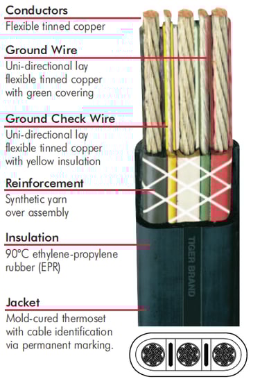
Conductors
The three power conductors are constructed from flexible tinned copper, assembled in a multi-strand configuration. Tinning the copper strands provides two critical benefits: it significantly improves resistance to corrosion in the wet, chemically active atmosphere common in underground mines, and it enhances solderability during field splicing and termination.
The high strand count — for example, 133 strands in 7x19 configuration for 6 AWG, or 259 strands in 7x37 for larger sizes — gives the cable exceptional flexibility. This is not a secondary characteristic. For equipment like shuttle cars that continuously spool and unspool cable across rough mine floors, flexibility directly translates into cycle life and total service length before replacement is required.
Reinforcement Layer
A synthetic yarn reinforcement layer is applied over the assembled conductor group before the outer jacket is applied. This layer distributes tensile loads across the cable's cross-section rather than concentrating stress at any single point. In practical terms, this means the cable can be dragged, bent around corners, and pulled over sharp rock edges with significantly less risk of internal damage than an unreinforced cable of comparable dimensions.
Ground Wire
The ground wire is a uni-directional lay flexible tinned copper conductor covered with green insulation for immediate visual identification. Its function is to provide a continuous low-resistance fault return path back to the power source. Should a phase conductor develop a fault to the equipment frame, the ground wire ensures the fault current returns quickly enough to trip the circuit breaker, protecting both equipment and personnel.
The uni-directional lay construction — all strands wound in the same direction — is important for flat cable designs because it prevents the cable from developing internal torque stresses during repeated flexing cycles.
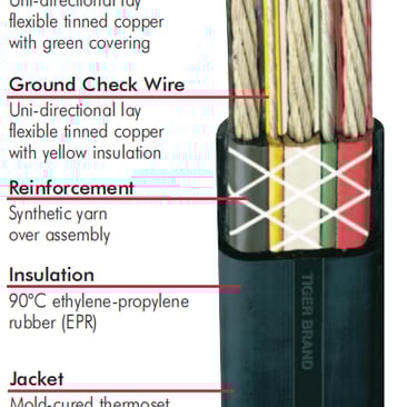
Ground Check Wire
The ground check wire is a separate, yellow-insulated conductor that enables continuous monitoring of ground circuit integrity. In underground mining, this is not an optional feature — it is a safety-critical system. The ground check wire is part of a pilot circuit that the equipment's ground fault protection relay monitors in real time. If the ground wire is broken, damaged, or disconnected at any point in the circuit, the relay detects the loss of the pilot circuit and removes power from the equipment before personnel can be exposed to an ungrounded fault condition.
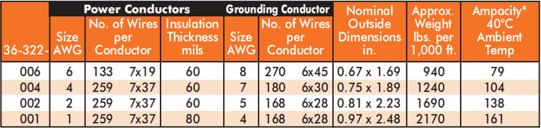
The ground check conductor on TYPE G-GC FLAT 3/C cable is a minimum of #8 AWG, which provides sufficient conductor mass to survive the same mechanical flexing cycles as the rest of the cable.
Insulation
Each conductor is individually insulated with 90°C ethylene-propylene rubber, commonly abbreviated as EPR. EPR insulation was developed specifically to address the failure modes that plagued earlier rubber compounds in high-voltage, high-temperature mining applications.
EPR delivers excellent electrical performance across the full rated voltage range, maintaining stable dielectric properties even when the cable is wet. It resists cracking and hardening at the temperature extremes encountered in underground environments — from cold intake air near portals to elevated temperatures near active cutting machinery. The 90°C continuous temperature rating means the insulation is not the limiting factor in conductor ampacity calculations under normal operating conditions.
Jacket
The outer jacket is a mold-cured thermoset compound applied over the entire flat cable assembly. Mold-curing, rather than continuous extrusion alone, produces a jacket with tighter dimensional tolerances and more uniform physical properties throughout the cable's length.
The jacket carries permanent marking for cable identification, which is essential for maintenance traceability in multi-circuit installations. It provides the primary defense against abrasion from mine floor contact, impact from falling rock and equipment, and chemical exposure from mine water, hydraulic fluids, and other substances present in the working environment.
Key Features of TYPE G-GC FLAT 3/C Cable
High Voltage Capacity at 2000V
The 2000V AC rating positions this cable appropriately for the medium-voltage systems used to power off-track mining equipment in underground coal and hard-rock mines. Most AC shuttle cars, drills, and continuous loaders in this segment operate on 995V or 1000V nominal systems, placing the cable well within its design envelope and providing a meaningful safety margin against transient overvoltages.
Flat Cable Design Advantages
The flat cross-section is the most visually distinctive feature of this cable, and it carries real operational consequences. Flat cables tend to lie flatter when placed on mine floors, reducing the likelihood that passing equipment will roll over a cable that has piled up in an arc. They spool more consistently on reel-equipped shuttle cars, reducing the uneven tension that causes premature wear in round cables when they spool unevenly.
For shuttle cars specifically, the cable must traverse the full length of a mining entry multiple times per hour. A flat cable's natural tendency to lie flat rather than coil means it is less likely to be run over, caught under equipment, or kinked at the termination points where the cable enters the machine's cable reel compartment.
Integrated Grounding and Monitoring
The simultaneous inclusion of both a ground wire and a ground check wire sets the G-GC designation apart from simpler cable types. This dual-function grounding system satisfies the requirements of modern ground fault protection systems used on AC mining equipment and complies with the grounding requirements of 30 CFR Part 75 for underground coal mines.
The green-jacketed ground wire provides the fault return path. The yellow-jacketed ground check wire provides the continuous monitoring signal. Together, they create a system where personnel exposure to ungrounded faults is prevented rather than simply detected after the fact.
Thermal Performance
The 90°C maximum continuous conductor temperature rating, combined with EPR insulation, allows this cable to carry its full rated ampacity in the ambient conditions typical of underground mines. Ampacity ratings are established at a 40°C ambient temperature baseline, with correction factors available for operations in higher or lower ambient conditions.
Applications in AC Off-Track Mining Equipment
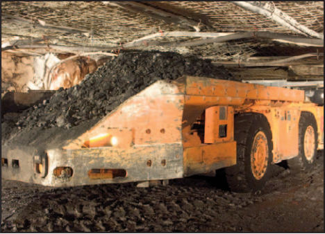
Shuttle Cars
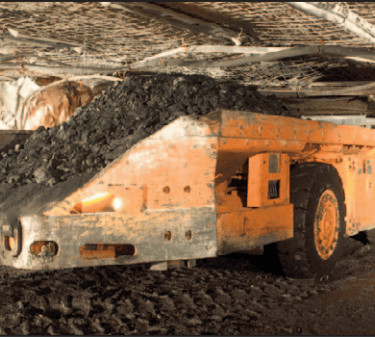
Shuttle cars are the primary application for TYPE G-GC FLAT 3/C cable. These battery-free, cable-powered haulage vehicles travel back and forth between the continuous miner and the feeder/crusher, continuously paying out and retrieving cable as they move. The cable must survive this repeated spooling cycle, absorb the shock loading when the car reverses direction, and resist damage from contact with the mine floor, ribs, and roof during tight turns.
In a longwall gate entry or room-and-pillar panel, a shuttle car may complete hundreds of round trips per shift. The cumulative mechanical stress on the trailing cable is extreme. The combination of flexible tinned copper conductors, synthetic yarn reinforcement, and mold-cured jacket found in TYPE G-GC FLAT 3/C cable is specifically engineered for this duty cycle.
Mining Drills
Roof bolters, exploration drills, and face drills move frequently within the working section, often being repositioned multiple times per shift. The cable connecting these machines must flex around tight corners, tolerate being dragged across rough floors, and survive the vibration transmitted through the drill frame during operation. Flat cables are easier to handle manually in confined spaces, which reduces the physical effort required to reposition cable when the machine moves.
Cutting and Loading Machines
Continuous miners, Joy-type miners, and similar cutting machines subject their trailing cables to a combination of tension, torsion, abrasion, and impact. While continuous miners in higher-voltage applications typically use SHD-GC type cables with metallic shielding, smaller cutting and loading machines operating in standard 2000V AC systems are well-served by TYPE G-GC FLAT construction where shielding is not required.
Other Mobile Mining Systems
Feeder-breakers, bridge conveyors, and mobile pumping stations that require portability and frequent repositioning can use TYPE G-GC FLAT 3/C cable where AC power, integrated grounding, and ground fault protection capability are all required and the operating voltage does not exceed 2000V.
Why TYPE G-GC FLAT Cable Is Preferred in Mining Operations
Mining electrical engineers and safety managers consistently select TYPE G-GC FLAT 3/C cable for several reasons that go beyond simple technical compliance.
The cable's integrated safety architecture — ground plus ground check — eliminates the need to run separate monitoring conductors or rely on equipment-side workarounds for ground fault protection. This simplifies installation, reduces the number of termination points that can fail, and ensures that the protection system operates as designed throughout the cable's service life.
The flat design contributes meaningfully to cable life in shuttle car applications. Round cables accumulate uneven tension across their cross-section when spooled, which accelerates fatigue at the outer layers. Flat cables distribute tension more evenly, reducing the internal stress concentrations that initiate jacket cracking and conductor wire breakage.
Maintenance teams in underground operations report that flat cables are easier to inspect visually, easier to repair in the field, and easier to handle in the confined access points of cable reel compartments. These operational factors translate directly into reduced downtime and lower cable cost per ton of production.
Performance in Harsh Mining Environments
Resistance to Abrasion and Mechanical Impact
The mold-cured thermoset jacket provides significantly better abrasion resistance than standard extruded jackets. Mining cable is routinely dragged across abrasive rock surfaces, crushed under equipment tracks, and impacted by falling roof material. The thermoset jacket maintains its integrity under these conditions over a service life that would rapidly destroy a standard industrial cable.
Resistance to Moisture and Chemicals
EPR insulation maintains its dielectric properties when wet. This is critical because mine workings are often wet from groundwater, dust suppression water, and hydraulic fluid leaks. A cable that loses insulation integrity when wet is a safety liability. EPR-insulated mining cable is designed to operate continuously in these conditions without degradation of electrical performance.
Flexibility Under Repeated Movement
The high-strand-count flexible tinned copper conductors maintain their flexibility throughout the cable's service life. Standard solid or low-strand conductors develop fatigue cracks in the wire strands after relatively few flex cycles. The fine-strand construction used in mining cable distributes flex stress across hundreds of individual wires, dramatically extending the number of flex cycles the cable can survive before strand breakage begins to increase resistance or create fault risk.
Stability in Temperature Variations
EPR insulation and thermoset jacket compounds retain their physical properties across the temperature range encountered in underground mining. Low-temperature brittleness, which can cause jacket cracking during cold-weather startup or when cable is stored outside, is not a concern with these materials within their rated operating range.
Real-World Mining Application Cases
Case Study: Underground Coal Mine, Appalachian Region
An underground coal mine operating room-and-pillar sections at depths of approximately 600 feet experienced frequent cable failures on its fleet of continuous haulage shuttle cars. The cables in service were a non-flat G-GC type, and the primary failure mode was jacket cracking at the cable reel entry point, where the cable experienced the tightest bend radius during spooling. The maintenance team averaged two cable repairs per shift across a three-car fleet.
After transitioning to TYPE G-GC FLAT 3/C cable, the spool-entry cracking failures were largely eliminated. The flat cross-section reduced the stress concentration at the reel entry point, and the mold-cured jacket proved more resistant to repeated bending in the same location. Cable repair frequency dropped by over 60% within the first three months of operation, and the mine's electrical supervisor attributed the improvement primarily to the flat cable's more uniform bending behavior on the reel.
Case Study: Hard Rock Metal Mine, Western United States
A hard rock underground copper mine was experiencing accelerated cable wear on its electric roof bolter fleet. The cables were routed through entries with standing water from active groundwater inflow, and the combination of submersion and mechanical abrasion from the bolter's cable tray was degrading cable jackets within four to six weeks of installation.
The operation switched to TYPE G-GC FLAT 3/C cable with attention to the mold-cured jacket specification and the EPR insulation. The EPR's moisture resistance addressed the electrical insulation concern, while the tighter-tolerance mold-cured jacket provided better abrasion resistance in the cable tray. Service life extended to an average of fourteen to eighteen weeks before replacement — more than double the previous performance — and no ground fault events were recorded during the evaluation period due to the intact ground check monitoring circuit.
Case Study: Potash Mine, Saskatchewan, Canada
A solution mining operation in a potash mine required trailing cables for mobile injection pumps operating in an environment with high humidity and chemically aggressive brine. Standard cable jackets were softening and swelling after contact with the potash brine, leading to jacket failures within weeks.
The engineering team specified TYPE G-GC FLAT 3/C construction with specific attention to the thermoset jacket chemistry. The mold-cured thermoset jacket demonstrated superior chemical resistance to the brine environment compared to the previous cable specification, and the EPR insulation maintained its dielectric properties without swelling or softening. The ground check monitoring system was particularly valued in this application because the brine environment created elevated ground fault risk, and the mine's safety protocols required real-time ground continuity monitoring on all mobile equipment.
Installation and Handling Best Practices
Recommended Bending Radius
Flat cables have a minimum bending radius that differs from round cables of equivalent conductor size. As a general guideline, the minimum bending radius for a flat mining cable should not be less than six to eight times the cable's major dimension during installation, and not less than four times the major dimension during operation (where the cable bends repeatedly). Exceeding this radius causes progressive damage to the conductor strands and jacket that is often invisible externally until the cable fails under load.
Proper Routing in Mining Machinery
Cable entry points on shuttle car reels and other cable-managed equipment should be inspected and maintained so that the entry radius does not force the cable to bend below its rated minimum. Worn or deformed entry guides are a leading cause of premature flat cable failure and should be replaced as part of routine equipment maintenance rather than waiting for a cable fault.
Avoiding Mechanical Stress Points
Flat cables should not be twisted longitudinally during installation. The flat cross-section has directional bending properties, and twisting imposes torsional stress that the cable is not designed to absorb. When running cable around corners, use appropriately radiused guides rather than forcing the cable over sharp edges.
Storage and Handling Recommendations
Store cable reels in a sheltered location away from ultraviolet exposure when not in use. UV exposure degrades thermoset jacket compounds over time, reducing their abrasion resistance. Reels should be stored upright and not stacked in ways that impose lateral crushing loads on the cable wound on lower reels.
Comparison with Other Mining Cable Types
G-GC vs TYPE W Cables
TYPE W cables are simpler constructions that omit the ground wire and ground check wire. They are appropriate for applications where the equipment does not require grounding conductors or where grounding is provided by another means. For any AC-powered mobile mining equipment where regulatory requirements or safety system design mandates ground fault protection through a pilot circuit, TYPE W cable cannot substitute for G-GC.
Flat vs Round Cable Performance Differences
Round G-GC cables are available in a much wider size range, including sizes up to 500 kcmil and beyond, making them the appropriate choice for higher-ampacity applications and for equipment like continuous miners and large longwall shearers. The flat configuration is particularly suited to shuttle cars and smaller equipment where cable management on a reel is a primary design constraint. Round cables offer better torsion resistance in applications where the cable rotates during equipment operation.
AC vs DC Mining Cable Considerations
TYPE G-GC FLAT 3/C is an AC cable. DC shuttle car applications use different cable types (such as TYPE W FLAT 2/C or TYPE G FLAT 2/C) because DC systems have different grounding and protection architectures. The ground check monitoring circuit in a G-GC cable is specifically designed for AC ground fault protection relays and is not compatible with DC haulage systems. Always confirm the system voltage type before specifying cable.
Common Challenges in Mining Cable Applications
Cable Fatigue and Wear
The most common cable failure mode in shuttle car applications is conductor fatigue from repeated flexing, typically manifesting first as increased conductor resistance followed by conductor strand breakage. Selecting cable with sufficient strand count for the required flex cycle life, and maintaining equipment cable guides and reel mechanisms in good condition, are the primary mitigations.
Space Constraints in Equipment Design
Cable reel compartments and cable entry points on older equipment were often designed for the cable sizes common at the time of manufacture. Upgrading to a larger conductor size for increased ampacity may require modification of cable management hardware to accommodate the larger cable's dimensions and bending radius requirements.
Maintaining Grounding Integrity
The ground wire and ground check wire must maintain electrical continuity throughout the cable's service life. Field splices are a common weak point. Splices must be made with properly rated connectors and techniques, and splice locations should be documented so they can be prioritized during inspection cycles. A damaged ground check wire that is not detected before the cable is returned to service defeats the purpose of the monitoring system.
Managing Heavy-Duty Operational Loads
Cable weight is a practical consideration for long haul distances. For shuttle cars operating in long entries, the weight of a fully extended cable affects the cable reel drive torque requirements and can contribute to mechanical wear in the reel drive system. Selecting the minimum conductor size that satisfies ampacity requirements — rather than over-specifying — reduces cable weight and cost while maintaining electrical performance.
How to Select the Right TYPE G-GC FLAT 3/C Cable
Matching Voltage and Load Requirements
Begin with the system operating voltage and confirm it does not exceed 2000V AC. Calculate the equipment's maximum continuous current draw, apply the appropriate derating factors for ambient temperature and installation conditions, and select the conductor AWG size whose ampacity at 40°C ambient meets or exceeds the calculated load current.
For shuttle cars, the nameplate motor current is typically the starting point. Many operations add a safety margin of 10 to 15 percent above nameplate current to account for motor aging and periodic overloads during heavy haul cycles.
Considering Environmental Conditions
Assess the cable's operating environment for the following factors: ambient temperature range, presence of standing water or active water inflow, chemical exposure (mine water pH, hydraulic fluids, dust suppression additives), and the mechanical environment (abrasive rock type, equipment cable management hardware condition, expected flex cycles per shift).
If the environment includes submersion or heavy chemical exposure, verify that the cable's EPR insulation and thermoset jacket specifications are adequate for the specific conditions. In extremely abrasive environments, thermoplastic polyurethane jacket alternatives may offer superior abrasion resistance compared to standard thermoset formulations.
Importance of Conductor Flexibility and Insulation Type
For high-cycle-count flex applications like shuttle cars, specify the highest strand count available within the applicable conductor AWG. Higher strand count directly translates to longer flex life. The difference between a 133-strand and a 259-strand construction at the same AWG is not cosmetic — it is a meaningful engineering choice that affects how long the cable survives in service.
Evaluating Safety Features Like Ground Check Wires
Confirm that the cable's ground check conductor size and strand count are compatible with the equipment's ground fault relay specifications. Some equipment manufacturers specify minimum ground check conductor resistance values or strand configurations. Verify compatibility before ordering cable to avoid discovering a mismatch during installation.
Future Trends in Mining Cable Technology
Increasing Demand for Integrated Safety Monitoring
The trajectory of underground mining electrical safety regulations in the United States, Canada, and Australia is toward more comprehensive real-time monitoring of cable and equipment electrical health. This creates demand for cables with additional integrated conductors to support expanded monitoring functions beyond the traditional ground check pilot circuit.
Fiber optic integration in composite mining cables is an emerging technology that allows data transmission alongside power delivery in a single cable, supporting real-time condition monitoring, equipment telemetry, and communication systems without separate data cable runs.
Advances in Flexible Insulation Materials
Research into next-generation EPR formulations and alternative thermoplastic elastomers continues to push the performance boundaries of mining cable insulation. Key development targets include improved resistance to ozone and UV degradation for surface applications, enhanced flexibility at low temperatures for cold-climate operations, and reduced jacket weight through higher-performance thinner-wall constructions that maintain equivalent protective properties.
Growing Focus on Durability and Lifecycle Cost Reduction
Mining operations are increasingly evaluating cable performance on a cost-per-ton or cost-per-operating-hour basis rather than simply purchase price. This lifecycle cost perspective favors higher-quality cable constructions that deliver longer service life, fewer failures, and reduced maintenance labor costs. TYPE G-GC FLAT 3/C cable's engineered construction directly addresses this calculus by prioritizing the mechanical and electrical durability features that determine real-world service life.
Google Featured Snippet: What is TYPE G-GC FLAT 3/C Cable?
TYPE G-GC FLAT 3/C cable is a 2000-volt AC portable mining power cable designed for off-track underground mining equipment such as shuttle cars, drills, and loading machines. It contains three flexible tinned copper power conductors, a green-covered ground wire, and a yellow-insulated ground check wire for continuous circuit integrity monitoring. The flat cable profile aids cable management on reel-equipped equipment, while the mold-cured thermoset jacket and 90°C EPR insulation provide durability in harsh underground environments. It meets MSHA listing requirements and ICEA Standards S-75-381/NEMA WC-58.
FAQ: TYPE G-GC FLAT 3/C Cable for Underground Mining
What does G-GC mean in mining cable terminology? In mining cable nomenclature, "G" indicates the cable includes a grounding conductor, and "GC" indicates the addition of a ground check conductor. Together, the G-GC designation means the cable supports both a fault return grounding path and a continuous monitoring pilot circuit for ground fault protection relays.
What is the difference between TYPE G and TYPE G-GC cable? TYPE G cable includes a ground wire for fault current return but does not include a ground check wire. TYPE G-GC adds a separate yellow-insulated ground check conductor that allows the equipment's ground fault protection system to continuously monitor ground continuity while the machine is operating. G-GC cables are required for AC equipment where ground fault relay protection uses a pilot circuit monitoring scheme.
Can TYPE G-GC FLAT 3/C cable be used for DC mining equipment? No. TYPE G-GC FLAT 3/C is designed for AC off-track mining equipment. DC haulage equipment such as DC shuttle cars uses different cable types — typically TYPE W FLAT or TYPE G FLAT — because DC systems use different grounding and protection architectures that are not compatible with the AC pilot circuit monitoring design of G-GC cable.
What conductor sizes are available for TYPE G-GC FLAT 3/C cable? TYPE G-GC FLAT 3/C cable is typically available in power conductor sizes ranging from 6 AWG through 1 AWG, with the corresponding grounding conductor sized proportionally smaller. The specific ampacity at each size is rated at 90°C conductor temperature and 40°C ambient. Larger conductor sizes are available in the round G-GC configuration for higher ampacity applications.
What is the minimum bend radius for TYPE G-GC FLAT 3/C cable? During installation, the minimum bend radius for flat mining cable is generally six to eight times the cable's major outside dimension. During repeated flexing in service (such as cable reel operation), the minimum bend radius is typically four times the major outside dimension. Exceeding these limits causes progressive mechanical damage to the cable.
Is TYPE G-GC FLAT 3/C cable rated for use in wet conditions? Yes. The EPR insulation used in TYPE G-GC FLAT 3/C cable maintains its dielectric properties when wet and is suitable for use in the wet conditions typical of underground mine workings. This includes contact with mine water, dust suppression water, and incidental submersion, though prolonged complete submersion at depth should be assessed against the cable's specific construction specifications.
What MSHA marking does TYPE G-GC FLAT 3/C cable carry? TYPE G-GC FLAT 3/C cable carries MSHA marking indicating listing by the Mine Safety and Health Administration and, for operations in Pennsylvania, the Pennsylvania Department of Environmental Protection. The cable also meets ICEA Standards S-75-381/NEMA WC-58, ASTM B-172, and ASTM B-33.
How does the ground check wire work in a G-GC cable? The yellow-insulated ground check wire forms part of a pilot circuit that runs from the equipment's ground fault protection relay, through the cable's ground check conductor, to the power center or substation and back. The relay continuously monitors the resistance of this circuit. If the ground wire in the cable is damaged or broken, the pilot circuit resistance changes, the relay detects the anomaly, and the equipment is de-energized before personnel can be exposed to an ungrounded fault condition.
When should I choose a flat G-GC cable over a round G-GC cable? Flat G-GC cable is preferred for equipment that uses a cable reel to manage the trailing cable — primarily shuttle cars and similar haulage machines. The flat cross-section spools more consistently, reduces cable pile-up on mine floors, and distributes bending stress more evenly during reel operation. Round G-GC cable is preferred for larger conductor sizes, higher-ampacity applications, continuous miners, and any application where torsional forces on the cable are significant.
Conclusion
TYPE G-GC FLAT 3/C cable represents a purpose-built engineering solution for one of underground mining's most demanding electrical applications. Its combination of flexible tinned copper conductors, EPR insulation, synthetic yarn reinforcement, integrated grounding and ground check conductors, and mold-cured thermoset jacket addresses the specific failure modes and safety requirements of AC off-track mining equipment.
For shuttle car operations, the flat design directly improves cable life and reduces the maintenance burden associated with reel wear and spool-entry cracking. For any application where AC ground fault protection through a pilot circuit monitoring scheme is required, the G-GC construction provides the necessary conductor architecture in a single, MSHA-listed cable assembly.
Selecting the right cable means evaluating conductor size against calculated load requirements, confirming EPR and thermoset jacket suitability for the specific environmental conditions, and verifying that the ground check conductor specification is compatible with the equipment's protection relay requirements. When these factors are properly matched, TYPE G-GC FLAT 3/C cable consistently delivers reliable service life and the grounding performance that keeps underground personnel safe.
Port crane cables | Mining cables | Reeling cables | Trailing cables | Festoon cables | Heavy-duty power cables | Medium voltage cables | Offshore crane cables | Underground mining cables | Dragline cables | Shearer cables | Container handling cables | STS crane cables | RTG cables | Mobile equipment cables | Armored cables | Flexible power cables | VFD cables | Submersible cables | Cold resistant cables | Abrasion resistant cables | Flame retardant cables | Marine environment cables | Opencast mining | Underground operations
© 2006 All rights reserved.
[INDUSTRIAL_CABLES]
INDUSTRIAL GRADE CABLE SYSTEMS | PORT & MINING SOLUTIONS
TEL: +86 153 7530 2641 |MAIL: hongjing.Wang@feichuncables.com