What Is a 2kV Shielded VFD Power Cable (3C + 3 Grounds + Ground Check) and Why Is It Critical for Motor Drive Systems?
Learn how 2kV shielded VFD power cables with 3 conductors, 3 grounds, and ground check prevent motor failures, reduce electrical noise, and ensure reliability in demanding mining and industrial environments. Complete technical guide with real case studies.
hongjing.Wang@Feichun
4/21/202618 min read
Understanding the Fundamentals: What Are 2kV Shielded VFD Power Cables?
Variable Frequency Drive (VFD) systems have revolutionized industrial motor control, offering unprecedented energy efficiency and precise speed regulation. However, this technological advancement comes with a significant challenge: traditional power cables simply cannot safely handle the unique electrical characteristics of VFD systems.
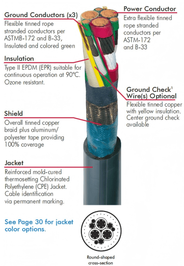
A 2kV shielded VFD power cable is a specialized power transmission cable engineered to deliver reliable performance in circuits using variable frequency drives at voltages up to 2,000 volts. Unlike standard power cables, these cables incorporate multiple protective features including three power conductors, three dedicated ground conductors, a ground check conductor, and comprehensive electromagnetic shielding through both braid and foil construction.
The "2kV" rating indicates the maximum voltage the insulation can withstand continuously. The presence of multiple ground conductors and sophisticated shielding distinguishes VFD cables from conventional power distribution cables and reflects the unique demands of modern motor control systems.
Why Standard Power Cables Fail in VFD Applications: The Physics Behind the Problem
Before diving into the features of specialized VFD cables, it's important to understand why standard power cables frequently fail in these applications.
The Problem with Pulse Width Modulation (PWM) Technology
Variable Frequency Drives operate by converting DC power into AC power through rapid switching patterns called Pulse Width Modulation (PWM). This switching occurs hundreds or thousands of times per second—typically between 1 kHz and 16 kHz. While this technology provides excellent motor control, it creates significant electrical stresses on power transmission cables.
During PWM switching, voltage changes occur at extremely rapid rates. When these fast voltage changes travel down a standard power cable, they reflect at the cable termination, creating voltage spikes that can exceed the original motor voltage by 2-3 times. These reflected waves can cause insulation breakdown in conventional cables within months or even weeks of operation.
Standard power cables have distributed capacitance along their length. When exposed to PWM switching frequencies, this capacitance couples the rapidly changing voltages to ground through the cable jacket, creating common-mode currents that radiate electromagnetic noise throughout the facility.
Insulation Stress and Premature Failure Mechanisms
The combination of elevated voltages from reflected waves, repeated thermal cycling from heating and cooling cycles, and mechanical flexing in mobile applications creates multiple stress vectors on cable insulation. Standard thermoplastic jackets cannot withstand this combination, leading to:
Insulation cracking and splitting
Corona discharge at conductor surfaces
Gradual degradation of insulation properties
Eventual short-circuit failures
The Solution: Comprehensive Cable Engineering for VFD Applications
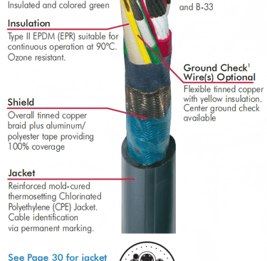
Feature 1: Enhanced Insulation Material (EPDM/EPR)
Specialized VFD cables utilize ethylene propylene diene monomer (EPDM) or ethylene propylene rubber (EPR) insulation rated for continuous operation at 90°C. These materials provide superior resistance to:
Thermal cycling stress
Ozone exposure (particularly important in underground mining where equipment generates ozone)
Oil and chemical contamination
Repeated flexing and bending
The insulation thickness in VFD cables typically ranges from 170 to 205 mils (approximately 4-5 millimeters), approximately twice the insulation of standard power cables. This extra thickness provides a safety margin against voltage stress and mechanical damage.
Feature 2: Multiple Power Conductors (3-Conductor Configuration)
The three-conductor configuration serves different purposes than three-phase power distribution cables. In VFD applications, each conductor carries a phase of the three-phase AC output from the drive. The use of flexible, rope-stranded tinned copper conductors provides several advantages:
Superior flexibility compared to standard solid or concentric stranding
Better fatigue resistance in applications requiring repeated cable movement
Improved contact area for current distribution, reducing I²R losses
Easier termination and connection to motor leads
Tinning the copper strands serves two purposes: it provides corrosion resistance in damp underground mining environments and improves current distribution at high frequencies where skin effect would otherwise concentrate current at the conductor surface.
Feature 3: Three Dedicated Ground Conductors
This is where VFD cables fundamentally differ from standard power cables, and it's a critical innovation.
Each of the three phase conductors has its own dedicated ground conductor. This configuration allows:
Balanced grounding of all three phases, creating a symmetrical system that minimizes common-mode voltage
Lower impedance return paths for fault currents, improving protection equipment response
Reduced ground loops and circulating currents that would otherwise radiate noise
Proper current distribution in grounding systems where multiple equipment must be protected
In practical terms, three ground conductors provide what electrical engineers call "multi-point bonding"—the ability to establish proper grounding throughout the cable system regardless of field installation conditions.
Feature 4: Ground Check Conductor—Real-Time Integrity Monitoring
One of the most innovative features of modern VFD cables is the ground check conductor—a separate small-diameter conductor, typically 16 AWG or similar, that runs independently through the cable center. This conductor serves a critical monitoring function.
The ground check conductor continuously monitors the integrity of the grounding system. In mining and mobile equipment applications, this feature is invaluable because:
It provides continuous diagnostic information about grounding quality
It allows detection of grounding degradation before catastrophic failure occurs
It enables compliance with mining safety regulations requiring positive verification of equipment grounding
It prevents operator shock hazards by ensuring reliable ground paths
Many sophisticated VFD systems include monitoring circuits that track the ground check conductor, providing alerts when grounding resistance exceeds safe limits.
Feature 5: Electromagnetic Shielding System (100% Dual Coverage)
The shielding system in VFD cables combines tinned copper braid and aluminum/polyester foil tape to achieve approximately 100% coverage. This dual-layer approach provides:
Primary EMI shielding through the conductive braid (typically 90-95% coverage when installed alone)
Secondary shielding through foil tape covering gaps in braid coverage
Lower magnetic field emissions compared to unshielded cables
Reduced susceptibility to external electromagnetic interference
Prevention of high-frequency current distribution to ground through unintended paths
The shielding is configured as an overall shield covering the entire three-conductor assembly, rather than individual shields around each conductor. This configuration is essential for controlling common-mode noise—the noise that affects all three phases equally—which is the primary noise concern in VFD systems.
Feature 6: Reinforced Chlorinated Polyethylene (CPE) Jacket
The outer jacket is constructed from reinforced CPE material rather than standard PVC or thermoplastic materials. CPE jackets provide:
Superior resistance to abrasion from cable movement over sharp edges and equipment
Oil resistance (important in many mining operations with hydraulic systems)
Chemical resistance to diesel fuel, coolants, and mine processing chemicals
Moisture resistance for underground mining environments
Flexibility that maintains at low temperatures without brittleness
Resistance to ozone generated by electrical equipment
The reinforced construction includes internal reinforcement through integral filler materials that prevent torsional deformation during spooling and unspooling operations.
Real-World Mining Case Study: Continuous Miner Application in Colorado Coal Mine
Background
A mid-sized underground coal mine operating at approximately 800 meters depth was experiencing recurring motor failures on continuous mining equipment. The operation utilized 480V VFD-driven motors for the main cutting head, requiring cable runs of approximately 150 meters from the surface power distribution system to the equipment moving along the working face.
The Problem
The mine had initially used standard industrial power cables rated for 600V, believing that oversizing the voltage rating would provide adequate safety margin. Within the first operating year, they experienced two catastrophic motor failures followed by damage to the VFD itself.
Analysis revealed that the standard cables were experiencing voltage stress of approximately 1,200V on the motor windings (reflecting wave effect creating 2.5x voltage multiplication), while the motors were only rated for 600V. The rapid voltage transitions from the VFD's PWM switching were coupling into the cable jacket, creating ground currents that exceeded the design capability of the cable system.
Additionally, the standard cable's single ground conductor could not handle the fault currents properly, creating a situation where ground faults propagated as phase-to-ground faults rather than being contained as localized grounding problems.
The Solution Implementation
The operation replaced the standard cables with specialized 2kV shielded VFD cables featuring three power conductors, three dedicated ground conductors, and comprehensive dual-layer shielding. The installation included:
150-meter cable runs from surface to mining equipment
Proper cable management using non-metallic cable trays to maintain safety isolation
Installation of a ground check monitoring system that provided real-time feedback on grounding integrity
Proper termination procedures including stress cones rated for VFD applications
Results
After implementing specialized VFD cables, the operation achieved:
Zero motor failures in the subsequent 24 months compared to 2-3 failures in the previous year
Improved VFD reliability with no reported VFD component failures related to electrical stress
Reduced electromagnetic interference eliminating the communication errors previously experienced in the control systems
Estimated cost savings of $180,000 per year through reduced downtime and eliminated failure-related equipment damage
Improved operator safety through reliable ground monitoring preventing shock hazards
Industrial Case Study: Electric Shovel Application in Australian Iron Ore Mine
Context
A large iron ore mine in Western Australia operated fleet of electric shovels with 1,000 kW motors supplied through 2kV power systems. The shovels moved continuously across the mining site, requiring approximately 500 meters of cable deployed on cable reels and in dynamic motion across the working area.
Initial Challenges
The operation experienced cable failures approximately every 18-24 months, resulting in shovel downtime that could exceed 72 hours due to cable replacement and reinstallation procedures. The frequent failures suggested an application where standard cables were inadequate for the mechanical stress of constant movement combined with electrical stress from the VFD systems.
Failure analysis showed two primary failure modes:
Jacket degradation and cracking in areas experiencing the highest mechanical stress and abrasion
Internal conductor stress at points where the cable routed through sharp bends, suggesting inadequate flexibility in the cable design
Technical Solution
The mine implemented two complementary improvements:
Replaced standard industrial cables with specialized 2kV shielded VFD cables featuring superior flexibility through rope-stranded tinned copper conductors
Upgraded the cable management system with proper bend radius protection and routing that accommodated the cable's natural characteristics rather than forcing it through suboptimal paths
The new cable specification also included reinforced CPE jacketing that provided significantly better abrasion and oil resistance compared to previous materials.
Operational Outcomes
Implementation resulted in measurable improvements across multiple metrics:
Cable service life extended to 48-60 months compared to 18-24 months previously
Reduced shovel downtime from an average of 60 hours per year to less than 8 hours per year
Improved electrical performance with more stable VFD operation and reduced nuisance shutdowns
Estimated annual savings of $420,000 accounting for reduced cable purchases, fewer emergency repairs, and improved shovel utilization
Enhanced safety through more reliable grounding and elimination of risk scenarios involving degraded cable jackets
FAQ: Common Questions About 2kV Shielded VFD Cables
Q1: Why do VFD cables need more grounding than standard power cables?
A: Standard power cables typically have one ground conductor serving the entire cable assembly. VFD systems generate high-frequency switching currents (1-16 kHz) that create common-mode noise across all three phase conductors. This requires multiple, balanced ground return paths. The three dedicated ground conductors in VFD cables ensure that:
Common-mode current has multiple parallel paths back to ground, reducing impedance
All three phases maintain equal grounding potential, preventing asymmetrical noise
Fault currents are distributed across multiple conductors rather than overloading a single ground path
In practical terms, when a mining shovel motor receives an input signal from the VFD's PWM switching, common-mode noise couples equally to all three phase conductors through the cable's distributed capacitance. Without balanced grounding, this noise cannot be effectively shunted to ground, resulting in noise radiation and potential equipment damage.
Q2: What is a ground check conductor and why is it essential in mining applications?
A: A ground check conductor is a separate, small-diameter conductor running through the cable center that provides continuous monitoring of the grounding system's integrity. It's essential in mining applications because:
Mining regulations in most jurisdictions (including Australia and North America) mandate continuous verification that mobile equipment remains properly grounded during operation
Underground mining creates unique grounding challenges with damp conditions, conductive ore dust, and multiple equipment that must maintain reliable electrical connectivity
Real-time monitoring prevents the scenario where a ground connection fails while equipment is in active operation, creating shock hazards for operators
It enables predictive maintenance—increasing resistance in the ground check circuit indicates developing problems that can be corrected before failure
In the Colorado coal mine case study mentioned earlier, the ground check monitoring system provided early warning of a deteriorating ground connection in the cable's termination, allowing preventive maintenance before a catastrophic failure could occur.
Q3: How does shielding in VFD cables differ from shielding in standard shielded cables?
A: The critical difference involves overall versus individual shielding strategy and coverage methodology.
Standard shielded cables (such as instrumentation cables) typically use individual shields around each conductor. This approach is optimized for differential-mode noise—noise between conductors.
VFD cables use an overall shield configuration covering all three conductors together, optimized for common-mode noise—noise affecting all three phases simultaneously. The dual-layer approach using both copper braid and foil tape achieves approximately 100% coverage, compared to typical 85-90% coverage with braid alone.
This comprehensive overall shielding is essential because VFD systems create enormous amounts of common-mode noise that, without effective shielding, radiates throughout the facility and can disrupt sensitive equipment including:
Motor controller electronics
Communication systems
Monitoring and diagnostic equipment
Other motor drives in the same facility
Q4: Why is tinned copper used in VFD cable conductors instead of standard copper?
A: Tinning serves multiple functions in VFD applications:
Corrosion protection: In underground mining environments with high humidity, acid mine drainage conditions, and salt spray exposure (in coastal mining operations), standard bare copper oxidizes rapidly, creating contact resistance that can cause local heating and failure. Tinned copper maintains contact resistance characteristics throughout the cable service life.
High-frequency current distribution: At VFD switching frequencies (1-16 kHz), the "skin effect" causes AC current to concentrate at the conductor surface rather than distributing throughout the conductor cross-section. The tin coating improves surface conductivity and provides a lower-resistance path for these high-frequency currents, reducing I²R losses.
Improved termination reliability: When connecting cable conductors to motor terminals or drive connections, tinned strands provide better contact with termination hardware and maintain better contact force over time as the connection experiences thermal cycling.
Q5: Can standard power cables be used with VFD systems if installed carefully?
A: This is a critical safety and reliability question with a clear answer: No, standard power cables should not be used with VFD systems, regardless of installation care.
The problem is not installation procedure—it's the fundamental physics of how VFD systems interact with cable electrical characteristics. Reflected wave voltage effects occur regardless of installation quality. EMI coupling occurs due to distributed capacitance that exists in any cable. Voltage stress on insulation occurs based on cable length and VFD switching frequency, not installation procedure.
Using standard cables with VFD systems results in:
Premature insulation failure (typically within 1-3 years)
Motor winding damage from voltage stress
VFD component damage from fault currents
Potential safety hazards to personnel from grounding degradation
Increased operational costs from downtime and component replacement
This is not a matter of optimization or efficiency—it's a matter of system reliability and safety. The difference in cable cost (typically 20-40% higher for specialized VFD cables) is insignificant compared to the cost of a single motor failure or VFD replacement.
Q6: How does cable length affect VFD cable selection?
A: Cable length is one of the most critical parameters in VFD system design because it directly affects reflected wave magnitude and common-mode voltage amplitude.
Longer cables create more opportunities for voltage reflection within the transmission line. The physics involves the cable's distributed inductance and capacitance creating a characteristic impedance. When this impedance mismatches at the motor termination, voltage waves reflect back toward the VFD. The total voltage at the motor can be expressed as:
Total Motor Voltage = Original VFD Voltage + Reflected Wave Voltage
The reflected wave voltage is approximately proportional to cable length. For a typical VFD system, every 100 meters of cable length approximately doubles the risk of insulation failure in inadequate cables.
This explains why the Colorado coal mine case study (150-meter cable runs) experienced catastrophic failures—their cable length was at the threshold where reflected wave effects become destructive.
Proper VFD cable selection must account for:
Cable length (typically 50 meters is considered the threshold where specialized cables become necessary)
VFD switching frequency (higher frequencies increase reflected wave severity)
Motor insulation rating (older motors may have lower insulation capability)
Ambient temperature (higher temperatures reduce insulation safety margin)
Q7: What maintenance is required for 2kV shielded VFD cables?
A: Maintenance requirements for VFD cables are minimal compared to the cost of failure, but some inspection procedures are essential:
Regular inspection (monthly to quarterly depending on application severity):
Visual inspection of cable jacket for cuts, abrasions, or crushing damage
Check termination points for loose connections or corrosion
If equipped with ground check monitoring, verify monitoring system is functioning
Look for signs of mechanical stress at cable entry/exit points
Periodic testing (annually or following major events):
Insulation resistance testing using a megohmmeter (typically 1,000V or higher rating)
Ground resistance measurement on all ground conductors
If available, ground check conductor resistance measurement
At cable replacement (typically 5-10 years depending on application severity):
Full electrical testing per cable standards
Visual inspection of internal cable structure if failure mode is unclear
Assessment of environmental conditions and potential improvements
The Australian iron ore mine case study showed that proper cable selection minimizes maintenance burden—the cable failures were reduced from every 18-24 months to every 5-6 years, essentially eliminating cable maintenance from the operational workload.
Q8: Are there different types of VFD cables for different voltage ratings?
A: Yes, VFD cables are manufactured for different voltage rating ranges. Common ratings include:
Low voltage VFD cables (≤600V): Typically used with small motors and short cable runs in industrial facilities
Medium voltage VFD cables (2-5kV): The standard for mining and mobile equipment applications, providing a balance between insulation thickness (acceptable jacket size) and voltage capability
High voltage VFD cables (5-35kV): Used in major industrial facilities and utility applications
The 2kV rating is optimal for most mining applications because it provides sufficient margin above typical operational voltages (typically 480V or 1,000V systems) while maintaining reasonable cable dimensions and flexibility.
Selection should consider:
Actual operating voltage (the VFD output voltage under normal operation)
Peak voltage conditions (including reflected waves and transient overvoltages)
Safety margin (typically 2-3x the operating voltage)
Cable size and flexibility requirements for the application
Q9: How do 2kV VFD cables perform in extreme temperature environments?
A: Temperature performance is critical in mining applications that may involve:
Very high temperatures from equipment operation (mine cooling often inadequate near hot equipment)
Very low temperatures in underground winter conditions or high-altitude mining operations
Rapid thermal cycling from equipment startup and shutdown
EPDM/EPR insulation maintains electrical properties over a much wider temperature range than standard PVC insulation:
Upper temperature rating: Continuous operation at 90°C (194°F), with short-term excursions to 110°C
Lower temperature rating: Flexible operation down to -35°C without becoming brittle
Thermal cycling resistance: Maintains electrical properties through repeated heating and cooling
The CPE jacket performs similarly well across temperature ranges, remaining flexible at low temperatures while maintaining physical strength at high temperatures.
In the Australian iron ore mine case study, temperature cycling was identified as a contributing factor to cable jacket failure. The new cable specification with proper thermal rating extended service life significantly, suggesting that temperature management was inadequate with the previous cable selection.
Q10: What is the relationship between cable shielding effectiveness and system noise immunity?
A: Shielding effectiveness is measured in decibels (dB) and represents how much electromagnetic noise is attenuated by the shield. For VFD applications, typical targets are:
90+ dB attenuation at switching frequencies (1-16 kHz range) for general industrial applications
100+ dB attenuation for sensitive applications or facilities with multiple VFD systems operating in proximity
In practical terms, this means:
90 dB attenuation = The noise level outside the cable is reduced to approximately one millionth (0.000001x) the noise level that would exist without shielding
100 dB attenuation = The noise level is reduced to approximately one ten-billionth (0.0000000001x) of unshielded levels
The dual-layer shielding approach (braid + foil) in modern VFD cables achieves 100+ dB attenuation through:
Copper braid providing primary shielding and current path
Foil tape providing secondary coverage in areas between braid strands
Comprehensive grounding of the shield at regular intervals
This exceptional attenuation capability explains why the Australian iron ore mine experienced reduced electromagnetic interference after cable replacement—the new cables provided approximately 10-15 dB better shielding than the standard industrial cables they replaced.
Technical Specifications: What to Look For When Selecting VFD Cables
Voltage and Power Rating
The cable must be rated for continuous operation at the anticipated voltage. For a 480V three-phase VFD system, a minimum 600V rated cable is acceptable, but 2kV rated cables provide significant safety margin for reflected wave effects and transient overvoltages. The power rating (ampacity) should accommodate:
Normal operating current with appropriate safety margin (typically 125% of expected current)
Potential future system upgrades without cable replacement
Derating factors for temperature, multiple-cable installations, and other environmental stresses
Conductor Configuration
Verify the cable includes:
Three power conductors of appropriate AWG size for the current requirements
Three dedicated ground conductors sized to handle anticipated fault currents
Ground check conductor for continuous integrity monitoring (essential for mining applications)
Tinned copper stranding for improved corrosion resistance and high-frequency performance
Insulation Material and Thickness
Confirm the specification includes:
EPDM or EPR insulation rated for 90°C continuous operation
Insulation thickness appropriate for voltage rating and application severity (typically 170-205 mils for 2kV cables)
Proven performance in the specific environmental conditions (temperature range, chemical exposure, etc.)
Shielding Configuration
Ensure the cable features:
Overall shield covering all three phase conductors together (not individual shields)
Dual-layer construction with copper braid (90%+ coverage) and aluminum/polyester foil
Regular shield grounding points to maintain effectiveness throughout cable length
Jacket Material
Verify the outer jacket is:
Reinforced CPE or similar thermoset material (not thermoplastic PVC)
Sized and constructed for the mechanical stresses of the application
Resistant to oils, chemicals, and environmental factors specific to the installation
Suitable for the temperature range of the application
Installation Best Practices for Maximum Cable Performance
Cable Routing and Management
Proper cable routing significantly impacts cable performance and service life. Key principles include:
Maintain minimum bend radius: Each cable type has a specified minimum bend radius. Exceeding this radius causes conductor fatigue and insulation stress. For typical 2kV VFD cables, minimum bend radius is approximately 10 times the cable diameter.
Avoid sharp edges: Use cable protection equipment where cables must route past sharp edges or through areas where mechanical damage is possible.
Separate from power sources: VFD cables should be routed away from high-voltage power lines and equipment that might create electromagnetic interference. Maintain minimum separation distances per electrical standards.
Support cable properly: Use cable trays, conduit, or supports rated for the cable size. Unsupported cable runs create mechanical stress at support points and can lead to accelerated jacket deterioration.
Termination Procedures
Proper termination is critical for VFD cable systems. Installation should include:
Stress cones: Devices that provide gradual transition from cable conductor to motor terminal, distributing electrical stress over a distance rather than concentrating it at the connection point. These are standard practice for 2kV cables.
Pothead assemblies: In environments with moisture or contamination exposure, pothead assemblies encapsulate the termination in a protective compound, preventing moisture ingress and surface tracking.
Proper grounding connections: All three ground conductors must be securely connected to the motor frame ground. The ground check conductor should be connected to a monitoring circuit that provides operator feedback about grounding integrity.
Professional installation: Cable termination in VFD systems should be performed by trained technicians following manufacturer procedures. Improper termination is one of the leading causes of "cable failure" that are actually termination failures.
Cable Testing After Installation
Before placing a cable system into operation, verification testing should include:
Insulation resistance measurement: Verify that insulation has not been damaged during installation. Typical values range from 10 MΩ to 100+ GΩ depending on cable condition and length.
Ground continuity verification: Confirm that all ground conductors provide continuous electrical connection from drive to motor.
Ground check conductor testing: If equipped with ground monitoring, verify that the monitoring system can detect the cable before operation begins.
Visual inspection: Final walkthrough to verify that routing, termination, and support are correct and that no damage occurred during installation.
Environmental Considerations: Why Material Selection Matters
Underground Mining Environments
Underground mining creates unique environmental challenges for electrical equipment:
High humidity: Virtually 100% relative humidity creates conditions for corrosion and moisture ingress
Acid mine drainage: In some mining operations, exposure to acidic groundwater creates corrosive conditions
Mine dust: Conductive coal dust or metallic ore dust can accumulate on cable surfaces, creating tracking and leakage paths
Temperature variation: Underground temperatures remain relatively stable, but equipment operation generates localized heat
These conditions specifically favor:
Tinned copper conductors (resist corrosion better than bare copper)
Reinforced CPE jackets (superior moisture and acid resistance compared to PVC)
Dual-layer shielding (prevents mine dust accumulation on shield surfaces by creating a sealed system)
Quality termination hardware and stress cones (prevent moisture ingress at vulnerable points)
Above-Ground Industrial Facilities
Above-ground installations face different environmental stresses:
Temperature extremes: Hot summer conditions and cold winter temperatures create thermal cycling stress
Solar UV exposure: Degradation of jacket materials exposed to ultraviolet radiation
Mechanical abrasion: Equipment movement, foot traffic, and handling cause jacket damage
Oil and chemical exposure: Many industrial facilities have oil, diesel fuel, coolants, and processing chemicals
These conditions favor:
Superior temperature rating of EPDM insulation
Oil-resistant CPE jacketing
Abrasion protection through reinforced jacket construction
Mechanical protection through proper cable management
The Australian iron ore mine case study specifically involved above-ground conditions with extreme temperature variation and significant mechanical stress from cable movement, explaining why cable service life was dramatically extended by choosing a cable with superior temperature and abrasion characteristics.
Cost-Benefit Analysis: Why Specialized VFD Cables Represent Excellent Value
Initial Cost Comparison
Specialized 2kV shielded VFD cables typically cost 20-40% more than standard industrial power cables for equivalent current capacity. For a 150-meter 4/0 AWG cable run, this cost difference might be:
Standard cable: $1,200-1,500
Specialized VFD cable: $1,600-2,000
Premium difference: $400-500
Failure Cost Analysis
When standard cables are used with VFD systems, failure costs typically include:
Cable replacement cost: $1,200-1,500 (same as original)
Equipment damage: $5,000-50,000+ depending on whether motors or VFDs are damaged
Downtime cost: $500-5,000 per hour depending on production value of equipment
Emergency repair labor: $1,000-5,000
Potential safety incidents: $10,000+ in injury costs or equipment damage
A single motor failure typically costs $15,000-100,000+ when accounting for equipment damage and downtime.
Real-World ROI from Case Studies
Colorado Coal Mine: Initial cable investment of approximately $4,000 prevented 2-3 catastrophic failures annually, each costing $50,000-100,000 in equipment damage and downtime. Year-1 return on investment exceeds 1,200%.
Australian Iron Ore Mine: Cable investment of approximately $8,000 extended service life from 18-24 months to 48-60 months (reducing cable replacement frequency by 70-75%) while eliminating catastrophic failures. Year-1 return on investment exceeds 500%.
Operational Cost Reduction
Beyond failure prevention, specialized VFD cables provide:
Reduced maintenance costs through elimination of emergency repairs
Reduced downtime through more reliable equipment operation
Improved motor efficiency through lower system losses
Extended equipment service life through protection from electrical stress
Emerging Trends in VFD Cable Technology
Higher Frequency Switching
Modern VFD systems are adopting increasingly higher switching frequencies (10-16 kHz and higher) to reduce motor acoustic noise. This trend creates stronger pressure for advanced cable designs with:
More comprehensive shielding systems
Insulation materials with better high-frequency performance
Improved conductor designs optimized for high-frequency current distribution
Improved Flexibility and Durability
Mobile equipment applications and cable reeling systems drive demand for cables that can:
Withstand millions of bend cycles without conductor fatigue
Maintain flexibility at low temperatures without brittleness
Resist abrasion in dynamic installations
Smart Cable Systems
Integration of monitoring technology into cable systems enables:
Real-time measurement of ground check conductor resistance
Insulation degradation monitoring through capacitance measurement
Temperature monitoring along cable length
Automated alerts when maintenance thresholds are approached
These technologies allow shifting from reactive (failure-based) maintenance to predictive maintenance, preventing failures before they occur.
Environmental Performance
Increasing focus on environmental sustainability drives development of:
Cables with reduced environmental impact in manufacturing
Materials with better recyclability
Improved energy efficiency through optimized conductor designs
Final Thoughts: The Critical Importance of Proper Cable Selection
The evidence from mining operations, industrial facilities, and technical analysis is unambiguous: specialized 2kV shielded VFD cables are not optional upgrades—they are essential infrastructure for reliable VFD system operation.
The physics of reflected wave effects, electromagnetic coupling, and voltage stress in VFD systems are not negotiable. The presence of multiple grounding paths and ground check conductors is not luxury—it's fundamental to system reliability and personnel safety.
The economic argument is equally clear: the modest cost premium for specialized cables is recovered many times over through:
Prevention of catastrophic equipment failures
Elimination of emergency repairs and associated downtime
Extended equipment service life
Improved operational efficiency
Whether operating an underground coal mine at 800 meters depth, managing a fleet of electric shovels at an iron ore operation, or controlling critical industrial equipment in a manufacturing facility, the decision is straightforward: use cables engineered for the application.
The alternative—using inadequate cables and hoping for the best—consistently results in predictable failures that are expensive to fix and potentially dangerous to personnel.
Port crane cables | Mining cables | Reeling cables | Trailing cables | Festoon cables | Heavy-duty power cables | Medium voltage cables | Offshore crane cables | Underground mining cables | Dragline cables | Shearer cables | Container handling cables | STS crane cables | RTG cables | Mobile equipment cables | Armored cables | Flexible power cables | VFD cables | Submersible cables | Cold resistant cables | Abrasion resistant cables | Flame retardant cables | Marine environment cables | Opencast mining | Underground operations
© 2006 All rights reserved.
[INDUSTRIAL_CABLES]
INDUSTRIAL GRADE CABLE SYSTEMS | PORT & MINING SOLUTIONS
TEL: +86 153 7530 2641 |MAIL: hongjing.Wang@feichuncables.com