What Is (N)3GHSSYCY Feeder Cable? A Complete Guide to Rubber Insulated PVC Sheathed Mining Power Cables
Discover the structure, specifications, and real-world mining applications of (N)3GHSSYCY feeder cable. Learn how this flexible rubber insulated, PVC sheathed cable performs in tunneling and underground industrial environments.
hongjing.Wang@Feichun
3/30/202612 min read
The (N)3GHSSYCY cable is a rubber insulated, PVC sheathed medium voltage feeder cable specifically engineered for underground mining and tunneling environments. It combines high mechanical flexibility with robust electrical protection, making it the preferred choice for stationary and non-stationary power distribution in mining infrastructure where standard armored cables fall short. Rated for voltages from 6/10 kV to 12/20 kV, this cable type is widely used across underground coal mines, hard rock tunneling projects, and heavy industrial installations worldwide.
Whether you are a procurement engineer selecting cables for a new tunnel boring project or an electrical contractor reviewing specifications for underground infrastructure, this guide covers everything you need to know — from construction details and electrical ratings to real-world deployment examples and common selection pitfalls.
Key Features of (N)3GHSSYCY Mining Cable
The (N)3GHSSYCY cable stands apart from conventional armored power cables through a combination of thermal endurance, mechanical resilience, and application-specific flexibility. Here is what defines this cable type.
High Flexibility for Movable Installations
One of the most critical attributes of (N)3GHSSYCY cable is its engineered flexibility, which addresses the unpredictable routing demands of underground mining environments. The cable achieves a minimum bending radius of 10 × D for flexible operation and 6 × D for fixed installation, where D is the outer cable diameter. For cables with outer diameters in the 51–75 mm range (as found in standard cross-section configurations), this translates to practical bend radii that accommodate tight corners in tunnels, around machinery, and along irregular rock faces.
This flexibility is essential in dynamic routing environments such as tunnel boring machine (TBM) corridors, where cables must trail behind advancing equipment and be repositioned frequently during excavation phases. The minimum S-type directional change spacing of 20 × D is a key specification that prevents fatigue damage at reversal points, particularly in cable festoon and drag chain installations.
Wide Operating Temperature Range
The cable is certified to operate safely under the following thermal conditions:
Fixed installation: surface temperature range from −40 °C to 80 °C
Flexible operation: surface temperature range from −25 °C to 80 °C
Maximum continuous conductor temperature: 90 °C
Maximum short-circuit conductor temperature: 250 °C
This wide range means the cable performs reliably in Arctic mining regions during sub-zero commissioning phases, as well as in deep underground workings where ambient temperatures can rise significantly due to geothermal heat. The 250 °C short-circuit rating is especially important for mining systems where fault current management is critical to personnel safety.
Strong Mechanical Performance
Mining environments subject cables to continuous mechanical stress — from vehicles driving over runs, rockfall debris, tensile loads during deployment, and repetitive flexing at connection points. The (N)3GHSSYCY cable is rated for a maximum tensile load of 15 N/mm² per conductor, providing substantial pull strength during installation without conductor deformation or insulation damage.
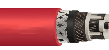
The galvanized steel wire braid armour (covering a minimum of 75% of the surface) provides crush and impact resistance without the rigidity penalties of solid armour constructions, preserving the cable's flexibility advantage.
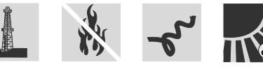
Flame Retardant and UV Resistant
The cable meets flame retardancy requirements under DIN EN / IEC 60332-1-2, which tests single vertical cable flame propagation. This is a baseline safety requirement for any cable used in enclosed underground workings where a cable fire can rapidly become a life-threatening incident due to smoke accumulation and limited escape routes.
The red PVC outer sheath is also formulated for UV resistance, allowing the cable to be used in outdoor staging areas, portal zones, and surface-to-underground transition sections without sheath degradation from solar exposure.
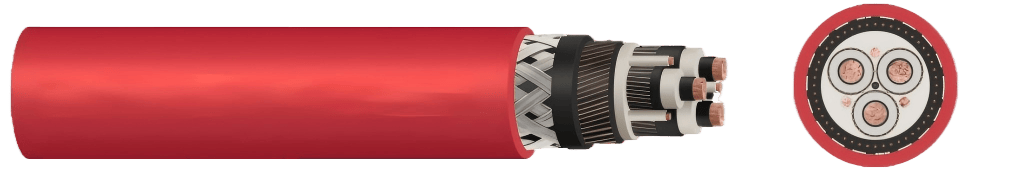
Cable Construction and Materials
Understanding the layered construction of (N)3GHSSYCY cable helps engineers verify suitability for specific applications and ensures compliance with procurement specifications.
Conductor Design
The main power cores use plain copper wires, finely stranded to IEC 60228 Class 5 — the highest flexibility class in the standard. Class 5 conductors consist of a large number of fine copper wires twisted together, enabling the conductor to flex repeatedly without work hardening or fracture. This is in contrast to Class 2 (stranded) or Class 1 (solid) conductors used in static power cables, which would fatigue rapidly under the repeated movement cycles common in mining applications.
The pilot cores (monitoring and control) are also Class 5 copper, insulated with a lead-free EPR compound for consistent signal integrity.
Insulation System
The insulation system on the main cores is a three-layer design:
An inner semi-conductive stress control layer that smooths the electric field at the conductor surface, preventing partial discharge initiation at conductor irregularities.
A mid-layer of EPR (Ethylene Propylene Rubber) compound, lead-free and formulated to DIN VDE 0207-20, providing the primary dielectric barrier. EPR is preferred over XLPE in mining cables because of its superior resistance to water treeing and its better performance under repeated mechanical flexing.
An outer semi-conductive insulation shield layer that controls the external electric field and ensures uniform stress distribution to the earth screen.
This triple-layer insulation architecture is standard practice for medium voltage cables and is essential for reliable service in the 6–36 kV range.
Sheath Structure
The sheath system consists of multiple protection layers working in combination:
The inner sheath 1 is a PVC compound (type DMV6, per DIN VDE 0276-603) applied over the laid-up core assembly. This is followed by the ÜL concentrical monitoring conductor — a set of plain copper wires forming a continuous loop with a DC resistance of ≤ 3.30 Ω/km at 20 °C. This monitoring conductor is a safety-critical feature that enables continuous sheath integrity monitoring, detecting damage to the outer protection before it creates an earth fault or personnel hazard.
Inner sheath 2 provides an additional PVC barrier before the armour, and the outer sheath is a red PVC compound (DMV6) that provides the final mechanical and environmental protection layer. The distinctive red colour is a mining industry convention that signals medium voltage power cables and provides immediate visual identification in cluttered underground environments.
Additional Structural Elements
The stranding arrangement places the three screened main power cores together with control cores positioned in the interstices (the spaces between the main cores), with plastic compound bedding filling any remaining voids. This compact geometry minimises overall cable diameter while ensuring mechanical stability — reducing the risk of core migration or armour bite during repeated flexing.
Electrical and Voltage Ratings
The (N)3GHSSYCY cable is produced in two primary voltage classes:
6/10 kV rated cables are rated for maximum operating voltages of 6.9/12 kV in AC systems and 9/18 kV in DC systems. This class is typically used for main feeder circuits supplying underground substations, ventilation fans, pumping stations, and large electric motors in medium-depth mining operations.
12/20 kV rated cables are rated for maximum operating voltages of 13.9/24 kV in AC systems and 18/36 kV in DC systems. These are used for longer distribution runs — particularly in deep mines where voltage must be stepped up to reduce transmission losses over distances of several kilometres from surface to underground working faces.
Testing compliance is maintained under DIN VDE 0250-1 (general requirements), DIN VDE 0250-813 (mining cable requirements), DIN VDE 0250-605 (electrical tests), and DIN VDE 0298-4 (current-carrying capacities and derating factors). Current-carrying capacities for specific cross-section configurations are referenced to DIN VDE 0298-4 and will vary by installation method, ambient temperature, and grouping factor.
Installation Conditions and Handling Guidelines
Correct installation practice is as important as correct cable selection. Mishandling during installation is one of the leading causes of premature cable failure in mining environments.
Fixed vs Flexible Installation
The distinction between fixed and flexible installation determines which bending radius limit applies during service. In fixed installations — where the cable is secured to a structure and not expected to move after commissioning — the 6 × D bending radius applies, and the lower temperature limit of −40 °C is permissible. In flexible operation — where the cable will be routinely repositioned, dragged, or flexed during normal use — the 10 × D radius must be maintained throughout the cable's service life, and the temperature floor rises to −25 °C.
Confusing these two categories is a common and costly error. A cable installed with the 6 × D radius in a position where it will actually flex in service will suffer insulation cracking and premature conductor fatigue failure.
Routing and Support Systems
The (N)3GHSSYCY cable is rated for installation on cable trays, planks, and gratings — the three most common cable support systems in underground mining. It is not rated for use in open mining operations or local operations where the cable would be dragged directly across rock surfaces, buried, or exposed to direct ground pressure without support.
For suspended tray installations, cable cleats or tie systems should maintain consistent spacing to prevent sagging and excessive lateral movement under dynamic load conditions. In S-type routing configurations — where the cable reverses direction in horizontal planes — the minimum spacing between directional changes must be maintained at 20 × D to prevent torsional strain accumulation at bend apexes.
Environmental Considerations
The cable carries a weather resistance rating of unrestricted use indoors and in mines, reflecting its suitability for the full range of humidity, water spray, condensation, and airborne particulate conditions found in underground workings. The RoHS 2015/863/EU compliance ensures the cable meets European restrictions on hazardous substances, and CPR 305/2011 (Construction Products Regulation) classification applies for EU projects.

Real-World Mining Applications
To illustrate where (N)3GHSSYCY cables are deployed in practice, the following cases represent typical scenarios from global mining and tunneling projects.
Tunnel Boring Operations — Australian Iron Ore Infrastructure
In large-scale tunnel boring projects such as those associated with iron ore infrastructure expansion in the Pilbara region of Western Australia, feeder cables of this construction type are used to supply power to TBM drive motors and ancillary systems. TBMs operating at depths of 50–300 metres require a continuous medium voltage power supply as they advance, meaning the feeder cable grows in length over months of operation. The high flexibility rating and Class 5 conductors allow the cable to be coiled on reels and paid out progressively as the machine advances, while the monitoring conductor enables continuous sheath integrity checking — critical in environments where a cable fault could halt a multi-million-dollar excavation programme.
Underground Coal Mining — Polish Hard Coal Basin
In the Silesian coal mines of southern Poland — some of the deepest coal operations in Europe, with working faces at depths exceeding 1,000 metres — medium voltage feeder cables of this construction are used for powering longwall shearer systems, armoured face conveyors, and stage loaders. At these depths, ambient rock temperatures can reach 40–45 °C, making the cable's 90 °C maximum conductor temperature rating an essential buffer margin. The flame retardant sheath is particularly critical in coal mines, where methane gas and coal dust create explosive atmosphere risks and cable fire propagation must be strictly controlled.
Nordic Hard Rock Mining — Swedish LKAB Operations
In underground iron ore operations in northern Sweden — where surface temperatures regularly fall below −30 °C in winter — cables must maintain performance during outdoor handling, transport, and installation even before they reach underground steady-state temperatures. The −40 °C fixed installation temperature rating of (N)3GHSSYCY cable makes it suitable for Nordic conditions where cables may be stored outdoors, run through unheated portal areas, and installed in near-surface galleries during winter construction phases.
Urban Tunneling — Road and Rail Infrastructure Projects
Beyond mining, this cable type is applied in urban tunneling projects such as metro rail construction and road tunnel boring in European cities. In the construction phase of a metro extension, for example, medium voltage cables supply tunnel boring equipment, ground freezing systems, and temporary lighting infrastructure. The UV resistance of the outer sheath is useful during surface works and open-cut sections before the tunnel is enclosed, and the cable's compliance with CPR regulations facilitates use in EU public infrastructure projects.
Advantages Compared to Standard Mining Cables
The (N)3GHSSYCY cable offers several performance advantages over conventional alternatives:
Compared to traditional solid-armour cables, the steel wire braid construction provides crush and abrasion resistance while preserving the bending flexibility that solid wire or tape armour eliminates. This means a single cable type can serve both the initial installation phase (where flexible routing is required) and the operational phase (where mechanical protection is needed), avoiding the cost and logistics of maintaining two cable types on site.
The EPR insulation outperforms XLPE in water-ingress resistance and flexibility at low temperatures, making (N)3GHSSYCY better suited than standard XLPE-insulated cables for the wet, cold, and mechanically demanding conditions of underground mining.
The integrated ÜL monitoring conductor is a feature not found in standard industrial cables but is standard in mining cable specifications — it enables proactive fault detection before cable damage leads to a power outage or, worse, a ground fault that endangers personnel.
Over the service life of a mining installation — typically 10 to 25 years — the combination of durable materials and correct installation practice supports substantially longer cable life compared to generic armored cables pressed into mining service, reducing replacement costs and unplanned downtime.
Common Selection Mistakes to Avoid
Even experienced procurement teams make avoidable errors when specifying mining feeder cables. The most consequential include:
Ignoring bending radius in dynamic applications. Selecting a cable on voltage and current ratings alone, without verifying the bending radius against the actual routing geometry, leads to premature insulation cracking at bends. Always measure the tightest bend the cable will experience in service and confirm it exceeds the 10 × D limit for flexible operation.
Underestimating tensile load requirements. In long vertical or inclined runs, the cable's self-weight generates tensile stress in conductors and sheaths. The 15 N/mm² tensile limit should be checked against the calculated hanging load for the longest unsupported run in the installation.
Incorrect temperature rating selection. Using fixed installation temperature limits (−40 °C lower bound) for cables that will actually flex at low temperatures risks insulation brittleness and cracking. Always apply the −25 °C flexible operation lower limit when the cable will be moved in cold conditions.
Misapplication in unsupported environments. Deploying (N)3GHSSYCY cable in positions where it will be dragged directly over rock floors without tray or plank support violates the cable's application classification and voids any warranty or standards compliance.
How to Choose the Right Feeder Cable for Mining Projects
Selecting the correct feeder cable for a mining or tunneling project requires systematic evaluation across four dimensions:
Voltage level is the first filter. Determine the system voltage at the point of cable installation and select the appropriate rated voltage class — 6/10 kV or 12/20 kV — with sufficient margin above the maximum operating voltage. Confirm AC and DC ratings separately if the system includes DC drives or rectifier-fed equipment.
Mechanical stress assessment must account for tensile load during installation and service, impact and crush risk from vehicles or rockfall, abrasion from cable contact with structure surfaces, and the number of flex cycles expected over the service life.
Installation type — fixed or flexible — determines the correct bending radius limit and temperature range to apply. If any doubt exists, apply flexible operation criteria as the conservative selection.
Environmental exposure analysis should cover ambient temperature range (including seasonal extremes for surface sections), moisture and water ingress risk, chemical exposure (acids, oils, mine water), UV exposure for portal and outdoor sections, and explosion risk classification for methane or dust environments.
Finally, verify that the selected cable carries the appropriate standards certifications — particularly DIN VDE 0250-813 for mining cable compliance and DIN EN / IEC 60332-1-2 for flame retardancy — for the jurisdiction and project type. For EU construction projects, CPR 305/2011 classification will be required by public procurement rules.
Frequently Asked Questions (FAQ)
What does (N)3GHSSYCY stand for?
The designation (N)3GHSSYCY is a German cable coding system used under DIN VDE standards. Each letter and number encodes a specific construction element. "N" denotes the standard (normtype). "3" indicates three main power cores. "G" refers to the rubber insulation (Gummi). "H" indicates a halogen-reduced or specific sheath compound class. "SS" refers to the steel wire braid screening/armour. "Y" indicates a PVC outer sheath. "C" denotes the integrated monitoring conductor (ÜL). Together, the code precisely describes the cable's construction to any engineer familiar with DIN VDE cable designation conventions.
Is (N)3GHSSYCY cable suitable for continuous movement?
Yes, provided the 10 × D minimum bending radius is maintained throughout the cable's movement cycle and the operating temperature stays above −25 °C. The Class 5 fine-stranded copper conductors and EPR insulation are specifically chosen to resist the mechanical fatigue caused by repeated flexing. However, the cable is not designed for festoon or cable reel applications with very high flex cycle counts — specialist trailing cable types should be evaluated for those use cases.
Can (N)3GHSSYCY cable be used in open-pit mining?
The cable is rated for unrestricted use indoors and underground in mines, and the UV-resistant outer sheath makes it suitable for outdoor portal and surface sections. However, it is specifically not rated for open mining operations where it would be dragged across ground without support or exposed to direct vehicle wheel loads. In open-pit environments, specialist surface mining trailing cables or protected direct-burial cable types should be considered.
What is the lifespan of this cable in harsh mining environments?
Service life depends heavily on installation quality, adherence to bending radius limits, and the severity of mechanical and chemical exposure. In correctly installed, supported, and maintained underground feeder circuits, cables of this construction type typically achieve 15 to 25 years of service life. Installations where the cable is routinely flexed, subjected to impact damage, or exposed to aggressive mine water without protective conduit may see significantly shorter service life. The integrated monitoring conductor allows proactive identification of sheath damage before it accelerates insulation degradation, supporting longer service life through timely maintenance.
What cross-sections are available?
Standard cross-section configurations range from 3 × 25 mm² (smallest, for lighter loads) to 3 × 120 mm² (largest, for high-current main feeders), with protective earth conductors and pilot cores sized proportionally. For 6/10 kV cables, outer diameters range from approximately 51 mm to 72 mm. For 12/20 kV cables, outer diameters range from approximately 57 mm to 75 mm. Custom cross-sections and core configurations can typically be produced to order by the manufacturer for specific project requirements.
Conclusion
The (N)3GHSSYCY rubber insulated, PVC sheathed feeder cable represents a well-engineered solution to the demanding and often conflicting requirements of underground mining power distribution: it must be flexible enough to route through complex underground geometry, robust enough to survive the mechanical violence of an active mine, and reliable enough to deliver uninterrupted power to equipment where downtime means halted production and potential safety risk.
Its core strengths — Class 5 flexible copper conductors, triple-layer EPR insulation, galvanized steel wire braid armour, integrated ÜL monitoring conductor, and flame-retardant UV-resistant PVC outer sheath — combine to produce a cable type that has earned its position as a mining industry standard across tunneling, underground hard rock, and coal mining applications globally.
For engineers and procurement professionals, the key discipline is correct specification: matching the cable's rated voltage, tensile load limit, bending radius, and temperature range to the actual conditions of the installation, rather than selecting on price or general suitability alone. Applied correctly, the (N)3GHSSYCY cable will deliver decades of reliable service in some of the world's most challenging electrical environments.
Technical specifications referenced in this guide are based on DIN VDE 0250-1, DIN VDE 0250-813, DIN VDE 0250-605, IEC 60228, DIN VDE 0207-20, DIN VDE 0276-603, and DIN VDE 0298-4. Always verify current product specifications with the manufacturer before finalising procurement decisions.
Port crane cables | Mining cables | Reeling cables | Trailing cables | Festoon cables | Heavy-duty power cables | Medium voltage cables | Offshore crane cables | Underground mining cables | Dragline cables | Shearer cables | Container handling cables | STS crane cables | RTG cables | Mobile equipment cables | Armored cables | Flexible power cables | VFD cables | Submersible cables | Cold resistant cables | Abrasion resistant cables | Flame retardant cables | Marine environment cables | Opencast mining | Underground operations
© 2006 All rights reserved.
[INDUSTRIAL_CABLES]
INDUSTRIAL GRADE CABLE SYSTEMS | PORT & MINING SOLUTIONS
TEL: +86 153 7530 2641 |MAIL: hongjing.Wang@feichuncables.com