What Is TYPE SHD-PCG Longwall 5000V Cable? Construction, Applications, and Selection Guide for Underground Mining
Discover TYPE SHD-PCG Longwall 5000V cable — its construction, key components, and real-world applications in longwall mining. Learn how to select the right heavy-duty cable for harsh underground environments.
hongjing.Wang@Feichun
4/15/202614 min read
What Is TYPE SHD-PCG Longwall 5000V Cable?
TYPE SHD-PCG Longwall 5000V cable is a heavy-duty portable power cable specifically engineered for longwall shearer systems in underground mining, combining three shielded power conductors, three unshielded control conductors, and a centrally located grounding conductor in a single mold-cured jacket rated for circuits not exceeding 5,000 volts.
Unlike general-purpose mining cables, the SHD-PCG design integrates power delivery, equipment control, and fault protection into one robust assembly. This consolidated architecture is critical for longwall operations, where continuous movement, extreme mechanical stress, and high electrical demands make cable reliability a direct factor in production uptime.
The "SHD" designation refers to the shielded construction of the power conductors, "P" indicates the inclusion of a control group, "C" denotes the central ground conductor placement, and "G" reflects the grounding conductor system. The 5kV rating positions this cable in the medium-voltage class, capable of supporting the high power demands of modern longwall shearers running at 5,000 volts AC.
Why Longwall Mining Demands Purpose-Built 5000V Cables
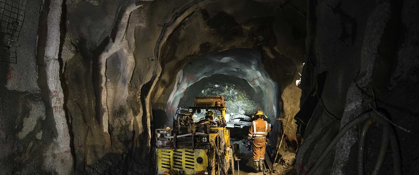
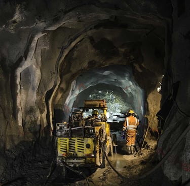
Longwall mining is one of the most mechanically aggressive environments in any industry. The shearer — a massive rotating drum cutting machine — travels back and forth along a coal face that can stretch several hundred meters, dragging its trailing cable behind it continuously throughout each shift.
In this setting, standard mining cables simply fail. The reasons are straightforward. Repeated flexing over thousands of cycles causes insulation fatigue. Abrasion from coal, rock, and equipment contact wears through outer jackets. Moisture infiltration compromises insulation resistance. And the simultaneous need to carry high-voltage power and low-voltage control signals in the same cable run demands a design that prevents electrical interference between circuits.
The 5000V rating addresses a broader industry shift. As longwall panels grow longer and shearers become more powerful, the electrical loads required to drive cutting drums, haulage systems, and hydraulic power packs have grown substantially. Operating at 5kV rather than 2kV allows operators to deliver the same power with lower current, which reduces heat buildup in the cable and allows for smaller conductor cross-sections — both significant advantages in a space-constrained underground environment.
Beyond raw power delivery, the SHD-PCG cable must also carry control signals that govern shearer position, interlock functions, and emergency shutdown sequences. These signals must remain clean and interference-free even while running alongside high-voltage conductors. The integrated shielding and physical separation within the cable construction make this possible in a single, manageable cable run.
Key Construction Features of TYPE SHD-PCG 5000V Cable
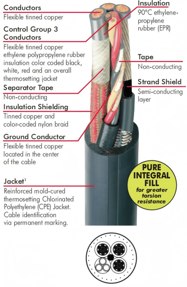
Power Conductors
The three main power conductors are built from flexible tinned copper stranded to high strand counts, allowing the cable to bend repeatedly without work-hardening or developing stress fractures in individual wires. Tinning the copper strands provides corrosion resistance in the wet, acidic environment common in many coal and metalliferous mines.
Each power conductor is individually shielded, which serves two functions: it controls the electrical stress distribution around each conductor at 5,000 volts, and it provides a defined ground reference that improves the sensitivity of ground fault detection systems. Without per-conductor shielding at this voltage level, the electric field stress at the conductor surface can cause partial discharge events that progressively degrade the insulation over time.
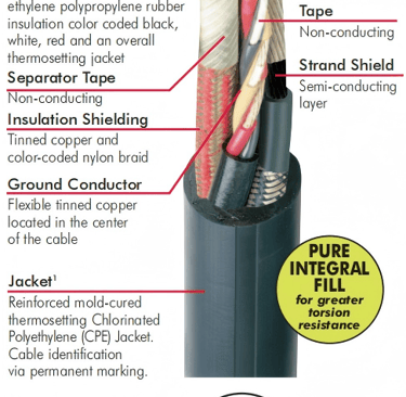
Control Conductors
The three-core control group consists of unshielded flexible copper conductors insulated with ethylene propylene rubber (EPR) and color coded black, white, and red for identification. These conductors carry low-voltage signals for shearer control functions — speed commands, direction inputs, safety interlocks, and position feedback.
The control group is assembled with an overall thermosetting jacket before being cabled into the main assembly alongside the power cores. This sub-jacket keeps the control group intact and provides an additional layer of physical separation from the power conductors.
Insulation System
EPR insulation rated at 90°C continuous conductor temperature is the standard across both power and control conductors. EPR was chosen for mining cable applications because of its combination of electrical performance and flexibility at low temperatures. It maintains good dielectric properties across a wide temperature range and resists the electrical aging mechanisms — particularly partial discharge — that degrade other insulation compounds in medium-voltage service.
The 90°C rating is meaningful operationally: cables can be loaded to their full ampacity rating without the insulation degrading prematurely, even in the elevated ambient temperatures sometimes found in deep mining operations.
Insulation Shielding
Over each EPR-insulated power conductor sits a shielding system consisting of a tinned copper layer combined with a color-coded nylon braid. The copper provides the electrical shielding function — terminating the electric field at the conductor surface and providing a path for capacitive charging current. The nylon braid serves as a mechanical restraint and provides phase identification capability.
At 5,000 volts, this shielding layer is not optional. Without it, uncontrolled electric field stress concentrations at the insulation surface would initiate partial discharge activity that progressively erodes the insulation from the inside out, leading to premature failure.
Strand Shield (Semi-Conductive Layer)
Between the conductor stranding and the EPR insulation sits a semi-conducting layer — the strand shield. This layer fills the microscopic air voids between individual copper strands and the insulation interface, eliminating the sharp geometric transitions where electric field stress would otherwise concentrate. Without this layer at medium voltage, those stress concentrations would trigger partial discharge at the conductor-insulation boundary, a leading cause of insulation failure in medium-voltage cables.
The strand shield is a feature specific to the 5kV SHD-PCG construction that is absent from the 2kV version, reflecting the different stress management requirements between the two voltage classes.
Ground Conductor
A flexible tinned copper ground conductor is located in the geometric center of the cable assembly. Central placement is deliberate: it provides the most symmetrical ground path relationship to all three power conductors, improving the sensitivity and speed of ground fault relay systems. In underground mining, the continuity and effectiveness of the grounding system is a primary safety mechanism, and the central ground conductor placement in the SHD-PCG design reflects this priority.
Separator and Non-Conductive Tapes
Throughout the cable assembly, non-conducting separator tapes are applied at critical interfaces — between the power conductors and the control group, and between individual sub-assemblies. These tapes serve multiple purposes: they maintain the designed geometry of the cable under flexing, prevent the abrasion of adjacent insulated surfaces against each other, and provide a clean separation plane during splicing and termination work.
Outer Jacket
The outer jacket is a reinforced mold-cured thermosetting chlorinated polyethylene (CPE) compound. Mold-curing — rather than continuous extrusion — produces a jacket with more uniform physical properties and better resistance to the crushing and impact loads common in longwall gate roads.
CPE was selected as the jacket compound because of its broad chemical resistance. It resists the hydraulic oils used in longwall roof support systems, the coal dust and water sprays present during cutting, and the occasional contact with fuel or lubricant spills common in any mechanized mining environment. The compound is also inherently flame-resistant, meeting the requirements of mining safety regulations for cables used in underground coal mines.
The jacket is available in multiple colors for circuit identification purposes, a practical safety feature when multiple cables of similar physical appearance run through the same cable handling system.
Real-World Applications in Underground Longwall Mining
Longwall Shearers
The primary application for TYPE SHD-PCG 5000V cable is powering and controlling the longwall shearer itself. A modern longwall shearer is among the most power-intensive pieces of equipment in any mine, with cutting motors, haulage systems, and ancillary drives drawing combined electrical loads that can exceed several megawatts in the largest installations.
The trailing cable connects the shearer to a power center mounted on the armored face conveyor or in the gate road, traveling with the shearer as it traverses the face. The 5kV rating allows this power to be delivered at reasonable current levels, keeping the cable cross-section manageable for the cable handlers and reeling systems used to manage the trailing cable.
Stage Loaders and Gate Conveyors
In the longwall gate road, stage loaders and gate belt conveyors carry the cut coal from the face to the main haulage system. These drives are typically powered from the same 5kV distribution as the face equipment. Where SHD-PCG cable is specified for this application, the integrated control conductors allow the stage loader drive to be interlocked with the shearer and the armored face conveyor in a coordinated start/stop sequence.
Armored Face Conveyors
The armored face conveyor — the chain-driven pan line that runs the full length of the longwall face — is powered by multiple drive units at the head gate and sometimes at intermediate points. These drives require reliable medium-voltage power delivery in the most abrasive location on the face. SHD-PCG cable routed to these drives must withstand contact with coal, rock, and the pan line structure itself during normal operations.
A Practical Example: Retreat Mining Operations
In a retreat longwall panel — where the face advances toward the setup room and the gate roads behind the supports are allowed to close — cable management becomes increasingly constrained as the panel retreats. The trailing cable must be managed through an ever-narrowing gate road cross-section while maintaining its electrical and mechanical integrity.
In this scenario, the SHD-PCG cable's integrated construction becomes a direct operational advantage. Rather than running separate power and control cables — which would require additional cable handling hardware, more splice connections, and a larger collective footprint in the gate road — a single SHD-PCG cable carries both functions. Operators at mines running retreat panels in the Illinois Basin and the Appalachian coalfields have reported that consolidating to integrated longwall cables reduced the frequency of cable-related production delays, as fewer cables meant fewer potential failure points in a confined routing environment.
High-Output Operations in Western Longwall Mines
Longwall operations in the western United States — including the large panel mines in Utah and Colorado — typically run at higher production rates and longer panel lengths than their eastern counterparts. Panel lengths exceeding 4,000 meters are not unusual, which means the trailing cable must be engineered not only for electrical performance but for the cumulative mechanical fatigue of thousands of shearer passes over the full panel length.
At these operations, the selection of 5000V cable over 2000V alternatives is driven by the power requirements of larger cutting drums and the economics of reduced current at higher voltage. The 5kV SHD-PCG cable allows the mine's electrical infrastructure to deliver adequate power to the face without requiring excessively large cable conductor cross-sections that would compromise flexibility and handling.
How to Select the Right TYPE SHD-PCG Cable
Matching Voltage and Load Requirements
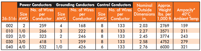
The first selection criterion is straightforward: if your longwall shearer or face equipment operates from a 5kV supply, you need the 5kV SHD-PCG construction (catalog reference 36-516). The 2kV version (36-504) serves 2,000-volt systems and should not be used on 5kV circuits.
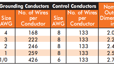
Within the 5kV SHD-PCG range, conductor sizes from 2 AWG through 4/0 AWG are available. The correct conductor size is determined by the ampacity requirements of the connected equipment at the prevailing ambient temperature. Ampacity tables for these cables are referenced to 90°C conductor temperature at 40°C ambient, and correction factors apply for different ambient conditions. For cables wound on a reel, additional derating factors apply because the wound layers cannot dissipate heat as effectively as a cable laid flat.
Evaluating Mechanical Stress Factors
Trailing cable applications impose mechanical demands that go beyond the electrical requirements. The minimum bending radius of the cable must be respected during installation and during normal shearer traversal — violating the minimum bend radius causes insulation damage and conductor fatigue at the bend point.
The reeling and unreeling cycle imposed by the cable management system is also a key consideration. Cables that are reeled and unreeled multiple times per shift accumulate torsional stress if the reel system does not properly support the cable's natural lay. The pure integral fill construction used in the SHD-PCG cable helps manage torsional loads by reducing the internal voids that allow individual conductors to migrate under repeated twisting.
Environmental Conditions Underground
The EPR insulation and CPE jacket of the SHD-PCG cable are well-matched to the typical underground mining environment, but the specific conditions at your operation should still be assessed. Operations with particularly aggressive hydraulic fluids, unusual chemical exposures from ground treatment programs, or extreme temperature ranges should verify compatibility before committing to a large cable purchase.
Where abrasion is an exceptionally severe concern — such as where cables are dragged directly over rough ribs or through cable slots in armored face conveyor pans — a thermoplastic polyurethane (TPU) jacket option may offer better mechanical protection. TPU provides substantially higher abrasion resistance than CPE, though it is also somewhat stiffer at low temperatures.
Conductor Size and Flexibility Trade-offs
Larger conductor cross-sections carry more current but are inherently less flexible. For a given ampacity requirement, it is worth evaluating whether a higher voltage allows a smaller conductor to meet the same power delivery need. This trade-off is one of the practical arguments for operating at 5kV rather than 2kV in high-power applications: the smaller conductors permitted by higher voltage produce a more flexible cable that is easier to manage in the gate road.
Installation and Handling Best Practices
Proper installation of longwall trailing cable begins before the cable reaches the mine. Cable reels should be stored upright, protected from UV exposure (which can prematurely age CPE jackets even before installation), and handled with reel jacks or lifting equipment rather than forklift tines through the reel flange.
During installation, the cable should be paid off the reel in the direction of natural rotation — never pulled off over the end of a stationary reel, which introduces one twist per loop and accumulates torsional stress. The cable run should be inspected for pinch points, sharp edges, and locations where the cable might contact moving equipment before energizing.
Minimum bending radius requirements must be observed at every bend in the cable route, including at the connection points to the shearer and at the cable handler drums. Violating the minimum radius — even temporarily during installation — can cause internal damage that is not visible from the outside but will result in premature failure in service.
Periodic inspection of the cable jacket for cuts, abrasion damage, crushing marks, and heat damage is an essential maintenance practice. Many operations have moved toward systematic cable inspection protocols tied to planned maintenance shutdowns, which allows damaged cable sections to be identified and spliced or replaced before they cause an unplanned outage.
Common Failure Modes and Prevention
Jacket Abrasion and Mechanical Damage
The most common failure mode for longwall trailing cables is mechanical jacket damage — cuts, abrasion, and crushing from contact with cable handlers, armored face conveyor structure, and ground. Prevention focuses on routing the cable to avoid contact with moving parts, using cable handlers with smooth, appropriately sized guide surfaces, and maintaining adequate cable slack so the cable is not pulled taut against sharp edges.
Insulation Degradation
Thermal degradation of EPR insulation occurs when cables are consistently operated at conductor temperatures above the 90°C rating — typically the result of sustained overloading. Moisture ingress through damaged jacket sections can also lead to insulation deterioration through tracking and partial discharge. Maintaining the jacket integrity and respecting ampacity limits are the primary preventive measures.
Shielding Failure
Damage to the insulation shielding — the tinned copper and nylon braid layer over each power conductor — can manifest as elevated partial discharge activity that progressively damages the underlying EPR insulation. Shielding damage is typically caused by mechanical overloading at splice points or by flexing-induced fatigue at locations where the cable is repeatedly bent to the same radius. Splash-proof and strain-relief termination fittings that distribute the bending load over a longer cable length can reduce this failure mode at connection points.
Grounding System Issues
The central ground conductor must maintain continuity throughout the cable's life. A broken ground conductor eliminates the fault protection that the grounding system provides and creates a safety hazard. Ground continuity is typically monitored by the mine's ground fault relay system, which will alarm on loss of ground continuity. Regular testing of ground conductor resistance — particularly after splicing operations — is a basic maintenance requirement.
Featured Snippet: Quick Summary
TYPE SHD-PCG Longwall 5000V cable is a medium-voltage underground mining cable rated for circuits up to 5,000 volts. It combines three shielded power conductors (flexible tinned copper with EPR insulation and individual tinned copper/nylon braid shielding), three unshielded EPR-insulated control conductors (color-coded black, white, red), a central flexible tinned copper ground conductor, non-conducting separator tapes, and a reinforced mold-cured CPE outer jacket. It is designed specifically for longwall shearers and heavy mobile face equipment where power delivery and equipment control must be carried in a single trailing cable. Available conductor sizes range from 2 AWG to 4/0 AWG, with ampacity ratings up to 321 amperes at 40°C ambient.
FAQ: TYPE SHD-PCG 5000V Longwall Cable
Q: What does SHD-PCG stand for in cable terminology?
SHD stands for shielded — specifically referring to the individually shielded power conductors. P indicates the presence of a control (pilot) conductor group integrated into the cable. C refers to the central placement of the ground conductor within the cable assembly. G denotes the grounding conductor system. Together, the designation describes the cable's core functional architecture: shielded power, control group, central ground.
Q: What is the difference between SHD-PCG 2kV and SHD-PCG 5kV?
The 5kV version includes a strand shield (semi-conducting layer) over each power conductor in addition to the insulation shielding present in both versions. The insulation thickness is also greater in the 5kV construction to withstand the higher electric stress. The 5kV cable uses a thicker EPR insulation wall, features a strand shield layer absent in the 2kV design, and has grounding conductor sizes scaled to the higher fault energy associated with 5kV systems. The 2kV version does not include the strand shield.
Q: Can SHD-PCG cable be used for applications other than longwall shearers?
Yes. While the cable was designed for longwall shearer trailing cable service, it is suitable for any application requiring three shielded medium-voltage power conductors, integrated control conductors, and a ground conductor in a single flexible cable. Stage loaders, gate conveyors, and other mobile face equipment operating from 5kV supplies can also be served by SHD-PCG cable where the integrated control conductor group is useful.
Q: How is the control group in an SHD-PCG cable different from the power conductors?
The control conductors are unshielded — they do not have individual insulation shielding over each conductor. This is appropriate because the control group carries low-voltage signals (not 5,000 volts), so the electric stress management requirements that necessitate shielding on the power conductors do not apply. The control group has its own sub-jacket, which provides physical separation and mechanical integrity within the overall cable assembly.
Q: What jacket options are available for TYPE SHD-PCG 5000V cable?
The standard jacket is extra-heavy-duty (EHD) black CPE (chlorinated polyethylene). Colored CPE jackets in blue, green, orange, yellow, and red are available for circuit identification purposes. All colored jacket options maintain the same physical properties as the standard black jacket. For extremely abrasive environments, a TPU (thermoplastic polyurethane) jacket upgrade may be available, offering substantially higher abrasion resistance than CPE.
Q: What is the minimum bending radius for a longwall trailing cable?
Minimum bending radius specifications vary with conductor size and overall cable diameter. As a general guideline for flexible trailing cables in continuous flexing service, the minimum dynamic bending radius is typically six to eight times the cable's overall diameter. The specific requirement for a given SHD-PCG cable size should be confirmed with the cable manufacturer, as violating the minimum radius — even momentarily during installation — can cause insulation damage not visible from the outside.
Q: How does the central ground conductor placement improve safety?
Placing the ground conductor at the geometric center of the cable assembly ensures that the grounding conductor has an equal electrical relationship with each of the three power conductors surrounding it. This symmetrical geometry maximizes the sensitivity of the ground fault relay system: any fault current flowing from a power conductor to the cable's metallic components must pass through or near the central ground conductor, providing a reliable fault detection path. Asymmetric ground conductor placement can create unequal fault detection sensitivity depending on which phase develops a fault.
Q: How often should longwall trailing cables be inspected?
Most mine safety regulations require regular inspection of trailing cables, and best practice at high-production operations involves visual inspection of the full cable length at planned maintenance stops — typically once per week minimum in active longwall service. Insulation resistance testing and ground continuity verification should be performed after any splice work and periodically as part of a preventive maintenance program. Cables showing jacket damage, shield exposure, or evidence of overheating should be removed from service for evaluation before returning to operation.
Conclusion: Choosing the Right Cable for Your Longwall Operation
TYPE SHD-PCG 5000V cable represents a purpose-designed solution for one of underground mining's most demanding electrical applications. Its integrated architecture — combining shielded medium-voltage power conductors, a control group, and a centrally located ground conductor in a single mold-cured assembly — directly addresses the operational realities of longwall shearer service: continuous mechanical flexing, exposure to moisture and chemicals, the need for reliable control signal transmission alongside high-voltage power, and the spatial constraints of cable routing in active gate roads.
Selecting the right cable starts with the voltage and ampacity requirements of the connected equipment, then moves to the mechanical demands of the specific cable routing and handling system, and finally considers the chemical and temperature environment at the operating location. Getting this selection right is not merely a procurement decision — in longwall mining, cable reliability is a direct input to face availability, and face availability is the primary driver of production output.
For operations evaluating SHD-PCG cable or planning a change in cable specification, working through the ampacity calculation, bending radius requirements, and mechanical stress assessment with a cable application engineer before finalizing the order is time well spent.
Port crane cables | Mining cables | Reeling cables | Trailing cables | Festoon cables | Heavy-duty power cables | Medium voltage cables | Offshore crane cables | Underground mining cables | Dragline cables | Shearer cables | Container handling cables | STS crane cables | RTG cables | Mobile equipment cables | Armored cables | Flexible power cables | VFD cables | Submersible cables | Cold resistant cables | Abrasion resistant cables | Flame retardant cables | Marine environment cables | Opencast mining | Underground operations
© 2006 All rights reserved.
[INDUSTRIAL_CABLES]
INDUSTRIAL GRADE CABLE SYSTEMS | PORT & MINING SOLUTIONS
TEL: +86 153 7530 2641 |MAIL: hongjing.Wang@feichuncables.com