Why Standard Power Cables Fail on VFD-Driven Port Cranes: An Engineering Guide to Inverter Duty Cable Selection in High-Stress Harbour Applications
Learn why VFD-driven port cranes need inverter duty, EMC compliant cables with symmetrical grounding to reduce noise, protect motors, and improve reliability.
hongjing.Wang@Feichun
7/27/202617 min read
1. Introduction: Why VFD Crane Motors Need Special Cables
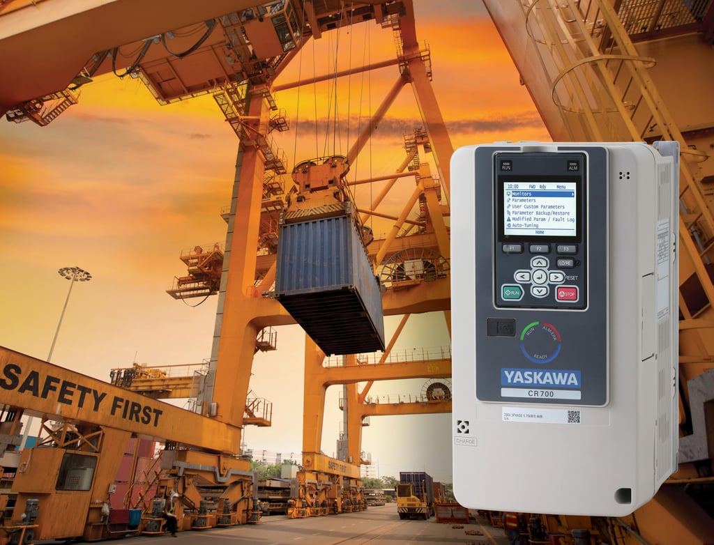
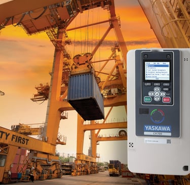
Modern harbour logistics, container handling, and bulk material transport depend on high-performance port cranes operating without unexpected disruption. Across major Australian shipping terminals—including Port Botany in Sydney, the Port of Brisbane, Port Hedland, Fremantle, and Gladstone—ship-to-shore (STS) container cranes, rail-mounted gantry (RMG) cranes, and rubber-tyred gantry (RTG) cranes are pushed to their operational limits. To achieve higher energy efficiency, precise torque control, regenerative braking, and smooth anti-sway motion, terminal operators have almost universally adopted Variable Frequency Drives (VFDs) to power their main hoist, trolley travel, and gantry motion motors.
While variable frequency drives offer clear advantages in machinery control and power savings, they introduce significant electrical stresses to the electrical delivery system. The power cable connecting an inverter drive to a crane motor no longer carries a clean, steady-state sinusoidal 50 Hz power supply. Instead, it carries high-frequency, fast-rising voltage pulses created by Pulse Width Modulation (PWM) switching.
A common point of failure on modern port machinery occurs when standard power cables, originally designed for fixed-frequency utility supplies, are installed on VFD-driven crane motors. Standard power cables often fail on VFD-driven port cranes because PWM switching introduces high-frequency voltage spikes, EMI, and reflected wave stress that ordinary cable designs are not built to handle.
When a general-purpose cable is subjected to the continuous electrical noise and voltage overshoot generated by a VFD—while simultaneously experiencing high reeling speeds, multi-plane bending, high axial tension, and aggressive coastal weather—the cable system degrades rapidly. Insulation breakdown, severe motor bearing fluting, encoder signal distortion, and premature cable destruction are the inevitable outcomes. For port engineers and equipment asset managers, choosing a specialized inverter duty cable is not merely a secondary wiring detail; it is a fundamental design requirement for protecting both the drive and the motor assets.
2. What Makes VFD Output Different
To understand why standard electrical cables breakdown under inverter control, it is necessary to examine the electrical output produced by a modern VFD.
A conventional utility grid delivers a smooth, continuous sinusoidal alternating current (AC) waveform at a fixed frequency of 50 Hz. In contrast, a variable frequency drive takes incoming 50 Hz AC power, rectifies it into a direct current (DC) bus voltage, and then uses solid-state insulated-gate bipolar transistors (IGBTs) to synthesize a variable-frequency AC output through Pulse Width Modulation (PWM).
CONVENTIONAL VS VFD OUTPUT WAVEFORMS Smooth 50 Hz Sine Wave (Utility Supply) PWM Fast-Switching Output (VFD Supply) +---+ +---+ +--+ +---+ +--+ +--+ / \ / \ | | | | | | | | +-------+-------+ +-------+-------+ +--+--+---+--+--+--+--+ \ / \ / | | | | | | | | +---+ +---+ +--+ +---+ +--+ +--+
Rather than producing a smooth wave, the inverter generates a series of steep, rectangular voltage pulses. These IGBTs switch on and off thousands of times per second—typically at carrier frequencies ranging between 2 kHz and 16 kHz. The speed at which these voltage pulses transition from zero to peak voltage is exceptionally fast. This parameter, known as rate of voltage rise (dV/dt), often exceeds 5 kV to 10 kV per microsecond.
These rapid dV/dt transition times transform the power cable from a simple conductive wire into a complex transmission line with significant distributed inductance, capacitance, and high-frequency wave behavior.
When high-frequency voltage pulses travel along a crane cable toward the motor, they encounter an impedance mismatch at the motor terminals. The electrical impedance of the motor windings is substantially higher than the characteristic impedance of the supply cable. This mismatch causes a portion of the incoming voltage wave to reflect back toward the inverter drive.
As these reflected waves collide with incoming voltage pulses, constructive interference occurs. This reflection wave phenomenon produces peak overshoot voltages at the motor terminals that can reach 2 to 2.5 times the nominal DC bus voltage. On a standard 690 V port crane supply system, these peak voltage spikes can easily exceed 1,600 V to 2,000 V, placing extreme electrical stress on the cable's primary insulation.
In addition, the fast rise times of PWM pulses generate significant high-frequency common-mode voltages relative to earth. This common-mode voltage drives high-frequency leakage currents through the parasitic capacitance existing between the cable phase conductors, earth conductors, metal screens, and surrounding structural steelwork.
3. Problems Caused by VFD Switching
When standard power cables are used in a VFD-driven crane installation, high-frequency PWM switching triggers several progressive failure mechanisms that jeopardize equipment reliability.
Partial Discharge and Corona Insulation Breakdown
Standard building wire and general-purpose industrial rubber cables rely on insulation materials sized primarily for nominal 50 Hz RMS operating voltages. When subjected to repeated high dV/dt voltage spikes exceeding 1,500 V, the electrical stress across microscopic air pockets within the insulation material exceeds the dielectric breakdown strength of air. This initiates localized electrical discharges known as partial discharge or corona effect.
Over time, partial discharge generates localized micro-arcing, extreme heat, and ozone gas within the insulation matrix. This chemical and thermal attack degrades standard insulation polymers (such as standard PVC or low-grade rubber compounds), eroding the material from the inside out until a total phase-to-phase or phase-to-ground dielectric puncture occurs.
Reflected Wave Peak Overshoot at Motor Terminals
As the distance between the VFD drive enclosure and the crane motor increases—a common situation on large ship-to-shore gantry cranes where long dynamic cable runs are required—reflected wave voltage peak overshoot becomes more severe. Without proper high-frequency voltage withstand capacity in the cable insulation, these peak voltage spikes penetrate magnet wire insulation inside the motor stator windings, resulting in phase-to-phase short circuits and motor burnouts.
Bearing Currents and Electrical Fluting Damage
One of the most destructive consequences of inappropriate VFD cabling is motor bearing failure caused by common-mode currents. High-frequency common-mode voltages created by the drive capacitive-couple onto the motor shaft. Because standard asymmetrical cables fail to provide a low-impedance, balanced path for high-frequency return currents, this electrical charge builds up on the motor rotor.
BEARING FLUTING FAILURE MECHANISM [ VFD Inverter ] ---> High dV/dt PWM Pulses ---> [ Asymmetrical Cable ] | Elevated Motor Shaft Voltage <--- Common Mode Current <---+ | v Discharges Through Bearing Oil Film (EDM Micro-Arcing) | v Pitting, Fluting Grooves, & Premature Bearing Failure
When the voltage on the shaft overcomes the dielectric resistance of the thin lubricating grease film inside the motor bearings, a sudden electrical discharge occurs. This electrical discharge machining (EDM) creates microscopic pits and washboard-like fluting grooves across the bearing races. Affected bearings exhibit excessive vibration, high operating temperatures, loud acoustic noise, and complete mechanical seizure within a fraction of their intended operating life.
Electromagnetic Interference (EMI) and Operational Disturbance
Unshielded or poorly grounded power cables act as large transmitting antennas for high-frequency electromagnetic noise. The rapid current pulses broadcast electromagnetic interference (EMI) and radio frequency interference (RFI) across the crane structure.
In modern automated ports, this radiated noise readily couples into nearby low-voltage instrument wiring, absolute encoder feedback channels, PLC communication buses (such as PROFINET or CANopen), and wireless telemetry systems. This interference leads to erratic crane positioning, false sensor tripping, data packet corruption, and unexpected emergency stop shutdowns.
Excessive Dielectric Heating and Charging Currents
High-frequency switching generates continuous high-frequency capacitive charging currents flowing through the dielectric insulation of the cable. In cables with high dielectric losses (such as standard PVC), these charging currents create internal dielectric heating. This supplemental thermal stress operates alongside the thermal energy generated by conductor load currents, accelerating thermal aging and shortening overall cable life.
4. Why Standard 3-Core + PE Is Not Enough
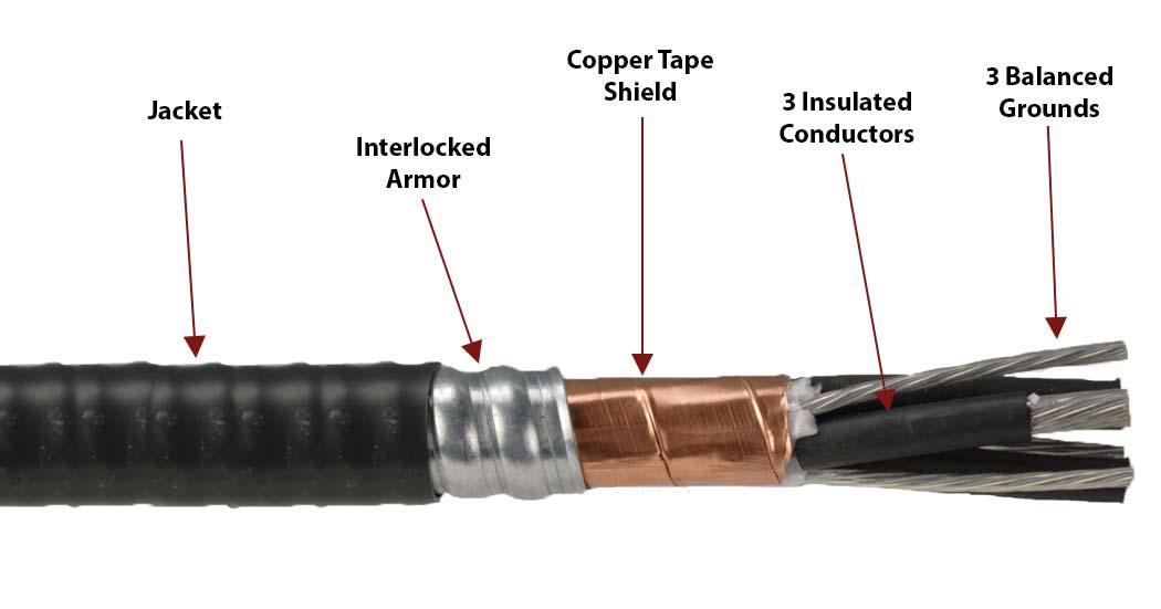
A standard industrial power cable structure consists of three insulated phase conductors (U, V, W) bundled together with a single protective earth (PE) conductor enclosed within an outer protective sheath. While this asymmetrical construction complies with low-frequency utility safety standards, it is inherently unsuitable for variable frequency drive operations.
CABLE CORE GEOMETRY COMPARISON Standard Asymmetrical Layout Symmetrical 3+3 Layout (High Common-Mode Noise) (Balanced EMC Suppression) [ U ] [ V ] [ U ] (PE) [ V ] \ / \ / / [ PE ] (PE) (PE) | \ / [ W ] [ W ]
In a standard three-core plus single earth cable, the geometric distance between each of the three phase conductors and the single PE ground conductor is unequal. Phase U and Phase V may lie physically closer to the single ground wire, while Phase W sits further away.
This spatial asymmetry creates unequal mutual capacitance and inductive coupling between individual phases and earth. Under steady 50 Hz conditions, this imbalance is negligible. However, when subjected to high-frequency PWM switching at several kilohertz, this geometric imbalance creates significant electrical problems:
Unbalanced Electromagnetic Fields: High-frequency currents returning through an asymmetrical ground wire generate unbalanced electromagnetic fields that radiate outward from the cable core, increasing EMI emissions.
High Ground Return Impedance: High-frequency currents suffer from the skin effect, travelling along the outer surface of conductors. A single round ground wire presents a higher high-frequency impedance than multiple distributed paths, forcing return currents to seek lower-resistance return paths.
Stray Structural Return Currents: Because the high-frequency return path through a single PE wire has higher impedance, a substantial portion of the common-mode current escapes the cable entirely. These currents travel back to the drive chassis through crane structural steelwork, metal cable tracks, bearing housings, and ground bonding straps.
Elevated Common-Mode Voltage: Asymmetrical ground layouts exacerbate net common-mode voltage at the motor terminals, directly increasing rotor shaft voltages and accelerating bearing fluting damage.
Attempting to run a high-power VFD motor through an asymmetrical 3+PE cable often results in persistent ground loop faults, drive trips, and ongoing bearing replacements.
5. Why 3+3 Grounding Matters
To address the electrical challenges created by PWM switching, high-performance VFD cable designs utilize a symmetrical 3+3 conductor architecture.
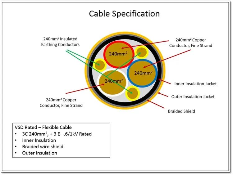
In a symmetrical 3+3 grounding cable, the main power transmission is carried by three primary phase conductors (U, V, W) spaced at 120-degree intervals. Rather than using a single ground wire, the total required protective earth cross-sectional area is divided into three identical, smaller earth conductors. These three split earth conductors are placed symmetrically into the outer interstices—the natural gaps existing between the main phase conductors.
In specialized medium-voltage flat reeling cables, symmetry is achieved by splitting the ground conductor into concentric shields or distributing matching earth cores symmetrically around each individual phase core.
SYMMETRICAL 3+3 GROUNDING BENEFITS [ Equal Phase Geometry ] ---> Zero Magnetic Field Net Output [ Parallel Ground Paths ] ---> Reduced High-Frequency Return Impedance [ Interstitial Placement] ---> Maximum Cable Roundness & Reeling Stability [ Shielded Current Return]---> Ground Currents Stay Inside Cable Sheath
This symmetrical geometry offers significant electrical and physical performance advantages for VFD applications:
Electromagnetic Symmetry and Field Cancellation
By placing three ground conductors at equal 120-degree intervals around the center of the cable, the vector sum of electromagnetic fields generated by both phase currents and high-frequency ground return currents approaches zero. The magnetic fields produced by common-mode noise cancel each other out, dramatically reducing external magnetic field radiation and preventing inductive noise coupling into adjacent control lines.
Reduced High-Frequency Impedance
Dividing the protective earth into three parallel conductors increases the overall surface area of the ground return network. Because high-frequency common-mode currents travel along conductor surfaces due to the skin effect, this configuration lowers the overall high-frequency return impedance of the grounding system. Common-mode currents are safely conducted back to the inverter frame through the cable's internal ground paths rather than straying into crane structural steel.
Mitigation of Bearing Currents
By providing an internal return path for common-mode currents directly through the symmetrical earth conductors, the common-mode voltage on the motor frame and rotor shaft is minimized. This prevents the build-up of destructive voltages across motor bearings, eliminating EDM micro-arcing and extending bearing service life.
Mechanical Roundness and Dynamic Stability
Beyond electrical performance, placing three identical earth conductors in the outer interstices produces a perfectly round, geometrically balanced cable core. For dynamic port crane applications—where cables are wound under high tensile loads onto high-speed reeling drums or flexed through energy chains—this symmetrical layout ensures uniform mechanical stress distribution, preventing core twisting, corkscrewing, and internal strand migration.
6. Shielding Structure for EMC Compliance
While a symmetrical 3+3 conductor design controls internal common-mode currents, achieving full Electromagnetic Compatibility (EMC) compliance across a port crane installation requires an effective overall shielding structure.
The primary objective of the cable shield is to form a continuous, low-impedance Faraday cage around the power conductors. This barrier prevents high-frequency electric fields generated by fast PWM switching from radiating outward, while simultaneously providing a low-impedance path for capacitive high-frequency currents to return directly to the drive.
OPTIMIZED DUAL-LAYER EMC SHIELDING [ Outer Protective Sheath ] Extra Heavy-Duty Rubber Compound (e.g., 5GM5) [ Tinned Copper Braid ] High Mechanical Strength & Low DC Resistance [ Metal Foil / Tape ] 100% High-Frequency Electrostatic Coverage [ Cable Core Assembly ] Symmetrical 3 Phase + 3 Earth Conductors
Two principal shielding methodologies—and their combination—are widely utilized in heavy-duty EMC compliant crane cables:
High-Coverage Tinned Copper Braid
Tinned copper wire braiding is the standard shielding approach for dynamic flexible and reeling cables. A tightly woven braid provides high physical coverage (typically 80% to 85% or higher) along with strong mechanical durability.
The braid offers low electrical resistance for returning high-frequency noise and easily withstands continuous flexing, axial pulling forces, and vibration on crane reeling drums. Using tinned copper strands prevents galvanic corrosion at shield terminations, which is critical in salt-laden coastal port environments.
Dual-Layer Shielding (Foil Tape + Copper Braid)
For highly sensitive EMC environments—such as automated container terminals operating delicate telemetry, optical sensors, and micro-motion controls—a dual-layer shield structure provides optimal performance.
This layout combines a 100% coverage aluminum-polyester foil tape layer with an overlying tinned copper wire braid. The inner foil tape provides complete electrostatic screening against high-frequency radio-frequency emissions, while the outer heavy-duty copper braid delivers mechanical reinforcement, high physical tear resistance, and a low-resistance path for high-frequency return noise.
Concentric Core Screening
In medium-voltage flexible reeling cables (such as 3.6/6 kV designs), EMC shielding is often integrated directly around each individual phase core. Concentrically distributed copper wire screens or semi-conductive elastomer layers enclose each phase core, ensuring 100% phase-to-phase isolation, uniform electrical field distribution, and containment of electromagnetic emissions.
To maintain shielding performance over the life of the cable, the shield layer must be encapsulated within an extra heavy-duty outer sheath. Specialized rubber compounds (such as Type 5GM3 or 5GM5 according to VDE 0207 Part 21) protect the delicate braid strands from moisture, oil contamination, mechanical abrasion, and fatigue failure caused by constant reeling.
7. Why Crane and Port Applications Are More Demanding
Installing a VFD cable on an outdoor port crane is far more demanding than running a stationary VFD cable inside a factory building. Port cranes subject motor cables to a harsh combination of simultaneous electrical, mechanical, and environmental stress factors.
COMBINED PORT OPERATIONAL STRESSES ELECTRICAL STRESSES MECHANICAL STRESSES ENVIRONMENTAL STRESSES --------------------- --------------------- ------------------------ - PWM High dV/dt Spikes - Fast Reeling (240 m/min) - Extreme Australian UV - Reflected Wave Peak Voltage - Torsional Stress (±25°/m) - Ambient Heat (70°C Surface) - Common-Mode Currents - High Tensile Loads - Marine Salt Spray & Humidity - EMI Radiated Noise - Roller Train Deflection - Hydraulic Oil & Greases
High-Speed Dynamic Motion and Tensile Loading
Port crane reeling cables are continuously wound and unwound at high travel speeds. Gantry travel speeds on modern container cranes reach up to 120 meters per minute or 240 meters per minute.
During rapid acceleration, braking, and direction changes, cables endure high dynamic tensile loads (often exceeding 20 to 30 N/mm² of total conductor cross-section). The cable core must resist these mechanical forces without allowing conductor strands to shift, stretch, or short-circuit against adjacent shielding layers.
Severe Torsional and Multi-Plane Flexing
As cables pass over guide sheaves, roller trains, and spreader baskets, they undergo multi-plane bending and severe torsional twisting. A cable operating on a ship-to-shore crane trolley can experience continuous torsional stress up to plus or minus 25 degrees per meter. If the cable construction lacks internal torsional reinforcement—such as an embedded synthetic anti-twist braid layer—this mechanical rotation can distort the core layout, leading to corkscrewing and catastrophic structural rupture.
Extreme Australian Environmental Exposure
Australia’s harsh climate presents severe challenges to outdoor electrical infrastructure:
Extreme Solar UV Radiation: Northern and coastal Australian ports experience extremely high UV index levels year-round. Solar radiation causes rapid photolytic breakdown of standard plastic sheaths, leading to surface cracking, chalking, and moisture penetration.
Elevated Thermal Extremes: In port locations like Port Hedland or Gladstone, summer ambient temperatures frequently exceed 40 to 45 degrees Celsius. Black rubber cable sheaths lying on exposed steel decking or gravel aprons can reach surface temperatures of 70 degrees Celsius or higher. Cables must maintain structural integrity and current-carrying capacity under these extreme thermal loads without softening or suffering accelerated insulation degradation.
Marine Salt Spray and High Humidity: Coastal port environments introduce a continuous fine mist of corrosive salt spray and damp, humid air. Moisture ingress into an unsealed or cracked cable sheath rapidly corrodes copper conductors and braid shielding, increasing resistance and degrading EMC performance.
Chemical Contaminants: Hydraulic fluids, gear lubricants, diesel exhaust soot, and abrasive mineral dusts (iron ore, coal, silica) cover cable sheaths, requiring high chemical resistance to prevent swelling, softening, and tearing.
When fast PWM voltage pulses occur simultaneously with physical twisting, dynamic tension, extreme ambient heat, and marine salt exposure, standard general-purpose power cables rapidly deteriorate. Engineered inverter duty crane cables are essential for surviving these combined operational hazards.
8. Recommended Cable Examples
To illustrate how these engineering principles are applied in modern port and mining machinery, consider three representative heavy-duty cable families manufactured by Feichun Cable. These examples demonstrate how symmetrical grounding, advanced insulation compounds, and extra heavy-duty sheathing are combined into reliable field solutions.
Feichun (N)TSKCGEWÖU High-Voltage Mining & Reeling Cable
The Feichun (N)TSKCGEWÖU cable family is engineered specifically for extreme mechanical stress, high reeling speeds, and high-voltage VFD drive applications in mining and heavy port machinery.
FEICHUN (N)TSKCGEWÖU CABLE CONSTRUCTION [ Phase Cores ] Class 5 Tinned Copper + Semi-Conductive Layers + EPR [ Earth Cores ] Symmetrical 3-Part Split Ground Layout (3+3 Design) [ Inner Sheath] Extra Heavy-Duty Vulcanized Rubber Bedding [ Anti-Twist ] High-Tensile Synthetic Thread Braid Layer [ Outer Sheath] Abrasion & Tear-Resistant Red PCP Rubber Sheath
Application Focus: Designed for heavy-duty motorized reeling drums, fast-moving container cranes, excavators, and mobile mining equipment where high dV/dt inverter output and high dynamic tensile loads occur simultaneously.
Electrical Architecture: Rated for medium- and high-voltage distribution (including 3.6/6 kV, 6/10 kV, 8.7/15 kV, up to 12/20 kV). It features finely stranded Class 5 tinned copper phase conductors enclosed by inner and outer semi-conductive stress-control layers over high-grade EPR insulation.
EMC & Grounding Geometry: Utilizes a symmetrical 3+3 grounding configuration, splitting the protective ground conductor into three equal parts positioned symmetrically in the outer interstices around a central semi-conductive filler core. This structure balances internal capacitance, suppresses common-mode noise, and limits shaft voltage build-up on motor bearings.
Mechanical & Thermal Ratings: Built with an integrated polyester anti-twist braid embedded between inner and outer rubber sheaths. It resists tensile loads up to 30 N/mm², withstands torsional stresses up to plus or minus 25 degrees per meter, and operates at reeling speeds up to 240 meters per minute. It performs reliably across a flexible operating temperature range from minus 30 degrees Celsius to plus 90 degrees Celsius (and minus 50 degrees Celsius in static conditions), with a maximum short-circuit rating of 250 degrees Celsius.
Feichun (N)TSFLCGEWOEU 3.6/6 kV Medium Voltage Flat Reeling Cable
The Feichun (N)TSFLCGEWOEU (ROTOLON series design) represents a specialized medium-voltage flat reeling cable developed for applications where installation space is restricted or where cables must run over multi-plane roller guide trains.
FEICHUN (N)TSFLCGEWOEU FLAT CABLE LAYOUT +-------------------------------------------------------------------+ | (PE) [ Phase U ] (PE) | (PE) [ Phase V ] (PE) | (PE) [ Phase W ] (PE) | +-------------------------------------------------------------------+ Concentrically Distributed Split Earth Conductors Around Each Phase Core
Application Focus: Primarily utilized on fast-moving container cranes, gantry travel mechanisms, stacker-reclaimers, and heavy mobile port equipment requiring flat cable reeling.
Conductor & Insulation System: Built with finely stranded Class F tinned electrolytic copper conductors for maximum flex life. The insulation system uses high-quality PROTOLON EPR-based compounds (Type 3GI3 quality), offering enhanced dielectric strength to handle peak voltage spikes caused by PWM switching.
Field Control & Shielding: Features an inner semi-conductive layer of EPR and a removable outer semi-conductive insulation shield layer. The core arrangement utilizes a parallel layout where the protective earth conductor is split and concentrically distributed around each individual phase core, providing symmetrical field containment and effective high-frequency noise screening.
Sheathing & Operating Parameters: Protected by a red PROTOFIRM CR extra heavy-duty rubber outer sheath (Type 5GM5 quality) offering outstanding resistance to mineral oils, weather, UV, moisture, and ozone. Rated for 3.6/6 kV (maximum permissible AC voltage up to 4.2/7.2 kV), it handles maximum tensile loads up to 15 N/mm² and supports gantry reeling travel speeds up to 120 meters per minute across an operating temperature range of minus 35 degrees Celsius to plus 80 degrees Celsius in flexible service.
Feichun NTSCGEWOEU-SR PLUS FO Dynamic Reeling Cable for Automated Cranes
For modern automated ports utilizing automated stacking cranes (ASCs), automated guided vehicles (AGVs), and remote-controlled ship-to-shore cranes, the Feichun NTSCGEWOEU-SR PLUS FO provides an integrated solution combining high-voltage VFD power transmission with real-time optical data communications.
FEICHUN NTSCGEWOEU-SR PLUS FO HYBRID DESIGN [ 3 Phase Power Cores ] Class 5 Finely Stranded Copper + EPR Insulation [ 3 Interstitial Earths] Symmetrical 3+3 Split Grounding Configuration [ Integrated Fibre Optics ] Single-Mode / Multi-Mode Optical Element Tubes [ Dual Sheath + Braid ] Extra Heavy-Duty 5GM5 Sheath with Anti-Twist Protection
Application Focus: Designed for automated port cranes and long-travel material handling systems requiring high-speed VFD drive control along with noise-immune feedback from absolute encoders, video cameras, and fieldbus communications.
Hybrid Construction: Houses three Class 5 finely stranded copper phase conductors with EPR insulation alongside integrated single-mode (9/125) or multi-mode (50/125 or 62.5/125) optical fiber elements contained within protective buffer tubes.
VFD & EMC Design: Features a symmetrical 3+3 split ground conductor design in the outer interstices. Integrating optical fibers into the power cable core allows control signals, encoder feedback, and automation data to transmit via light waves, rendering data channels immune to high-frequency EMI generated by adjacent power cores.
Heavy-Duty Mechanical Performance: Encapsulated in a dual extra heavy-duty 5GM5 rubber sheath separated by a synthetic thread anti-twist braid. Rated for dynamic reeling speeds up to 240 meters per minute, tensile forces up to 20 N/mm², and torsional stresses up to plus or minus 25 degrees per meter, it operates flexed from minus 35 degrees Celsius to plus 80 degrees Celsius (and minus 50 degrees Celsius fixed) with a short-circuit temperature withstand of 250 degrees Celsius.
9. How to Choose the Right VFD Crane Cable
Selecting the correct VFD cable for a port crane installation requires evaluating drive parameters, mechanical motion requirements, and site environmental conditions. Equipment specifiers and electrical engineers should follow a structured step-by-step selection logic:
VFD CABLE SELECTION DECISION PATHWAY [ DRIVE & ELECTRICAL ASSESSMENT ] - Is the motor fed by a VFD inverter? --------------> REQUIRES VFD CABLE - Are dV/dt filters or sine-wave filters present? - What is the peak voltage spike level? ------------> SELECT HIGH DIELECTRIC EPR/XLPE [ EMC & GROUNDING REQUIREMENTS ] - Are nearby encoder or control signals present? ----> SELECT EMC COPPER BRAID SHIELD - Is motor bearing protection critical? -----------> SELECT SYMMETRICAL 3+3 GROUNDING [ MECHANICAL & REELING DYNAMICS ] - What is the travel speed & reeling motion? -------> ROUND (240 m/min) vs FLAT (120 m/min) - What are the tensile & torsional loads? ---------> VERIFY ANTI-TWIST BRAID RATING [ ENVIRONMENTAL & DATA INTEGRITY ] - Is outdoor Australian UV/heat exposure present? --> SELECT 5GM3 / 5GM5 RUBBER SHEATH - Is automation feedback required? -----------------> SELECT HYBRID FIBRE OPTIC DESIGN
Step 1: Assess Electrical Drive Output and Insulation Needs
Determine the inverter carrier frequency, rise time (dV/dt), output voltage level, and total cable length between the drive panel and the motor. If the cable length exceeds recommended limits or operates without output filters, specify high-dielectric EPR or XLPE insulation compounds rated for 1,000 V or higher. Verify that the insulation can withstand peak voltage spikes of 1,600 V to 2,000 V without initiating partial discharge.
Step 2: Mandate Symmetrical 3+3 Grounding Geometry
For all inverter-fed crane motors, mandate a symmetrical 3+3 grounding configuration rather than an asymmetrical 3+PE design. Symmetrical grounding ensures balanced ground return paths, reduces common-mode currents, suppresses net electromagnetic radiation, and protects motor bearings from electrical fluting damage.
Step 3: Match Shielding Structure to the Operating Environment
Evaluate the electromagnetic sensitivity of the installation site. Select a high-coverage tinned copper braid shield (or a combined foil and braid shield) for installations where encoder lines, sensor wiring, communication buses, or radio controls operate near power cables. Ensure the shield is terminated around 360 degrees using EMC-compliant cable glands at both the drive enclosure and the motor terminal box to maintain shielding effectiveness.
Step 4: Evaluate Dynamic Mechanical Parameters
Select the physical cable construction based on machinery motion profile:
High-Speed Round Reeling: For high-speed motorized reels operating up to 240 meters per minute, select round cables with central filler support, interstitial earth cores, and embedded anti-twist braiding (such as Feichun (N)TSKCGEWÖU).
Flat Cable Profiles: For tight installation spaces, festoon systems, or flat roller guide trains operating up to 120 meters per minute, select flat reeling designs with concentrically shielded split ground conductors (such as Feichun (N)TSFLCGEWOEU).
Tensile and Torsional Limits: Confirm that maximum tensile ratings (e.g., 20 to 30 N/mm²) and torsional resistance ratings (e.g., ±25°/m) exceed the mechanical forces generated by the crane drum system.
Step 5: Verify Outer Sheath Compound Suitability
For outdoor crane applications in Australian ports, specify extra heavy-duty vulcanized rubber outer sheaths (such as Type 5GM3 or 5GM5 quality). Ensure the compound formulation provides tested resistance to solar UV radiation, extreme surface heat (70°C+), marine salt spray, hydraulic oil splash, and heavy mechanical tearing.
Step 6: Integrate Data Communication Requirements
If the crane installation requires automated PLC data, absolute encoder feedback, or remote video monitoring, consider hybrid power cables featuring integrated optical fiber elements (such as Feichun NTSCGEWOEU-SR PLUS FO). Transmitting control signals optically inside the main reeling cable eliminates electromagnetic interference risks while simplifying overall cable management.
10. System Reliability and Inverter Duty Integrity
In variable frequency drive applications on modern port cranes, standard general-purpose power cables present significant operational risks. Fast PWM switching generates high dV/dt voltage spikes, reflected wave peak overshoots, high-frequency common-mode currents, and radiated electromagnetic interference that standard cable constructions are simply not built to handle.
Attempting to save on initial capital costs by installing standard power cables on VFD-driven crane motors often leads to severe financial penalties—including insulation breakdown, destroyed motor bearings, distorted encoder signals, and costly unplanned operational downtime.
Specifying an engineered inverter duty cable—featuring symmetrical 3+3 grounding, high-dielectric insulation, 360-degree EMC shielding, and an extra heavy-duty outdoor rubber sheath—provides comprehensive protection for both the drive system and the motor. Cable series such as the Feichun (N)TSKCGEWÖU, (N)TSFLCGEWOEU, and NTSCGEWOEU-SR PLUS FO demonstrate how robust mechanical construction and advanced electrical design come together to handle demanding port applications.
For port engineers, crane builders, and asset maintenance teams operating across harsh harbour environments, selecting the proper VFD cable is a foundational requirement for ensuring long-term operational safety, equipment reliability, and low total cost of ownership.
Port crane cables | Mining cables | Reeling cables | Trailing cables | Festoon cables | Heavy-duty power cables | Medium voltage cables | Offshore crane cables | Underground mining cables | Dragline cables | Shearer cables | Container handling cables | STS crane cables | RTG cables | Mobile equipment cables | Armored cables | Flexible power cables | VFD cables | Submersible cables | Cold resistant cables | Abrasion resistant cables | Flame retardant cables | Marine environment cables | Opencast mining | Underground operations
© 2006 All rights reserved.
[INDUSTRIAL_CABLES]
INDUSTRIAL GRADE CABLE SYSTEMS | PORT & MINING SOLUTIONS
TEL: +86 153 7530 2641 |MAIL: hongjing.Wang@feichuncables.com