Why Tensile Strength Matters for Ship-to-Shore (STS) Crane Reeling Cables: A Guide for Middle Eastern Port Operators
Learn why tensile strength directly affects STS crane reeling cable life, dynamic stress resistance, and safe high-speed operation in demanding port environments.
hongjing.Wang@Feichun
7/10/202613 min read
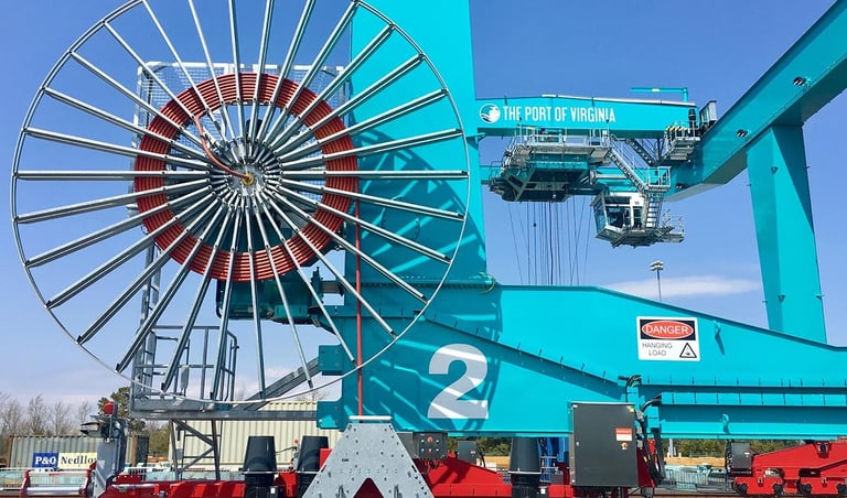
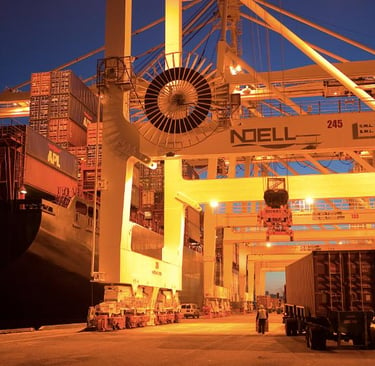
In the global maritime logistics landscape, the ports of the Middle East serve as critical mega-hubs connecting East and West. From the bustling berths of DP World’s Jebel Ali Port in the UAE and King Abdullah Port in Saudi Arabia, to the strategic gateways of Salalah in Oman and Khalifa Port in Abu Dhabi, operational efficiency is a non-negotiable mandate. At the heart of these modern automated and semi-automated terminals are Ship-to-Shore (STS) container cranes. These towering structures operate continuously to meet demanding vessel turnaround times.
Within an STS crane, no component is subjected to a more severe moving-cable environment than the reeling cable. Tasked with delivering high-voltage power and fiber-optic data continuity while being rapidly spooled onto and off a motorized reel, these cables are the literal lifelines of port infrastructure.
1. Introduction
The Core Thesis
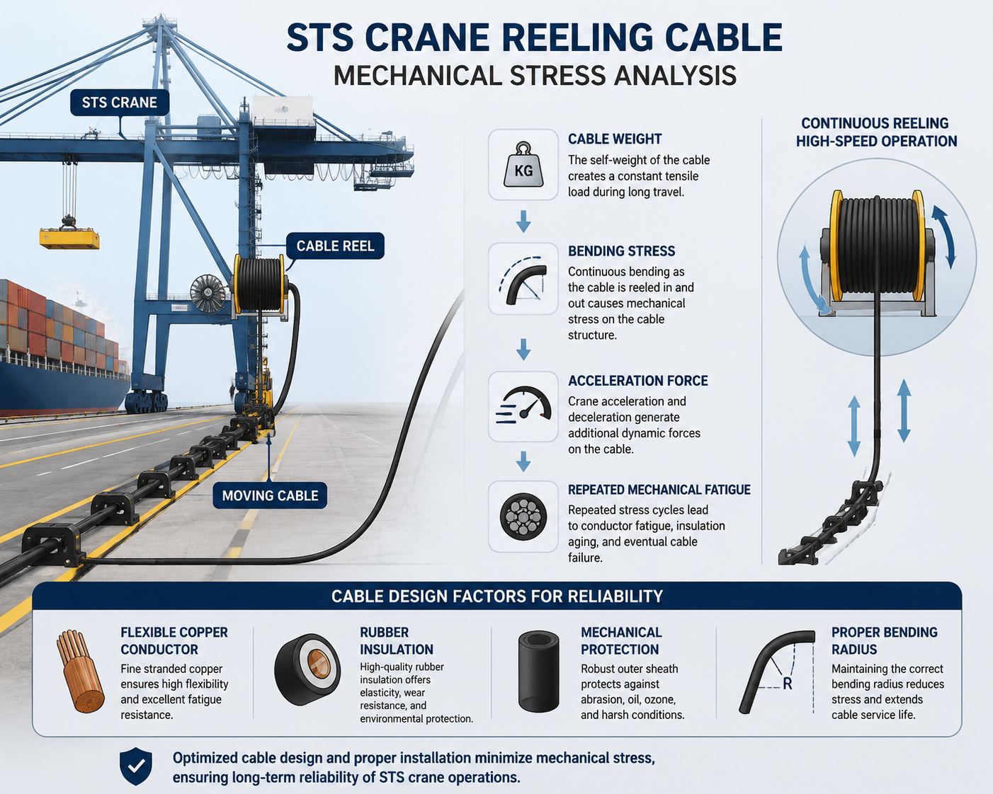
For port technical directors, engineering managers, and procurement heads across the region, cable selection often zeroes in on electrical parameters like ampacity and voltage ratings. However, field experience proves that tensile strength is not merely a structural specification; it is a direct, quantifiable driver of cable service life, operational safety, and terminal downtime reduction. STS cranes combine long travel distances, high operational speeds, continuous cyclic bending, and aggressive dynamic shock loads. This complex interplay of forces makes mechanical stress the primary driver of premature cable failure. In the harsh environment of the Middle East—where extreme ambient temperatures regularly exceed 50°C and combine with high humidity and abrasive airborne dust—mechanical stress is heavily compounded. If a cable lacks the engineered tensile strength to withstand these forces, catastrophic failure is not a matter of if, but when.
2. STS Crane Operating Conditions Create Severe Mechanical Stress
To understand why tensile strength is paramount, one must analyze the complex physics governing an active STS crane. The operation of an STS crane involves three distinct, simultaneous moving motions that place unique mechanical demands on the reeling cable:
Crane Travel (Gantry Motion): The entire crane structure moves parallel to the berth along gantry rails. This long-travel motion pulls the cable over vast distances, requiring high longitudinal tensile resistance.
Trolley Movement: The trolley travels perpendicularly over the vessel to lift and lower containers. While the reeling cable primarily services the main gantry travel, the acceleration profiles of the crane directly translate into whipping and dynamic tension spikes along the cable line.
Cable Reeling: The motorized reel actively winds and unwinds the cable. This requires perfect synchronization with the crane's gantry speed to prevent excessive slack (which leads to snagging) or over-tensioning (which leads to snapping).
Dynamic Stress Profiles in Numbers
To better understand the scale of these mechanical challenges, consider the typical operating parameters of modern mega-max STS cranes and how they generate operational stress:
For crane travel speed, a typical value ranges from 30 to 60 meters per minute. This specific motion matters because it creates a continuous longitudinal pull and repeated start-stop inertia loading on the cable assembly.
For trolley speed, values regularly reach between 60 and 240 meters per minute. High trolley speeds matter because they increase dynamic cable movement, transmit heavy vibrations, and induce severe bending fatigue across the structural run.
For reeling speed, operational systems generally run between 100 and 200 meters per minute. This speed factor matters because it raises tension fluctuations during sudden reel synchronization shifts as the crane accelerates or decelerates along the berth.
For travel distance, modern ports feature long-travel operational setups that often extend well over 60 meters. This long distance matters because it dramatically increases the cumulative mechanical cycles and adds significant deadweight to the cable section suspended in tension.
The Industry Standard View
The Port Equipment Manufacturers Association (PEMA) explicitly highlights these risks in its technical papers. According to PEMA, moving crane cables are continuously exposed to frequent flexing, severe mechanical stress, and excessive constant or dynamic tension.
PEMA emphasizes that long-travel dynamic applications extending beyond 60 meters, or operations operating at speeds above 240 meters per minute, transition into a high-risk engineering zone. These applications demand meticulous cable system design, where tensile strength stands as the primary line of defense against structural elongation.
3. What Tensile Strength Means in Crane Cable Design
In simple engineering language, tensile strength is the maximum mechanical stress a cable component can withstand while being pulled or stretched before experiencing permanent deformation, necking, or structural failure.
When a cable is pulled, it initially undergoes elastic deformation; if the tension is released, it returns to its original length. If the tension exceeds the material's yield point, it enters plastic deformation—meaning the internal components are permanently stretched. For a complex, multi-layered product like an STS reeling cable, this distinction is critical.
Conductor vs. Reinforcement Tensile Strength
An engineering distinction must be made between the two primary mechanical zones within a cable:
Conductor Tensile Strength: This represents the load-bearing capacity of the internal copper strands responsible for transmitting electrical energy or grounding. Copper is naturally ductile and is not designed to support the mechanical weight or pulling forces of a high-speed reeling system.
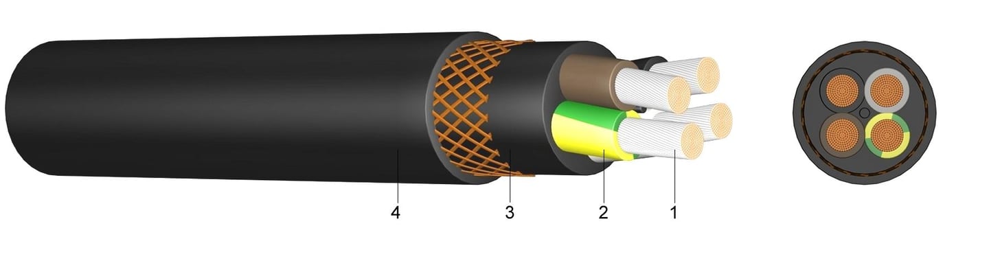
Reinforcement Tensile Strength: This represents the structural backbone—typically located in the center of the cable core, between the inner and outer sheaths, or integrated into the outer jacket. This layer is engineered solely to absorb structural tension.
In heavy-duty crane cables, the entire composite structure must be integrated so that the cable survives both its electrical duty (carrying high voltage without insulation breakdown) and its mechanical duty (withstanding immense pulling forces). If the reinforcement layer fails to absorb the tension, those forces are transferred directly to the copper conductors, leading to rapid electrical failure.
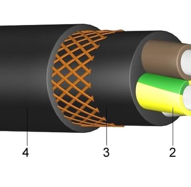
4. Tensile Strength of the Conductor
To maintain flexibility during thousands of winding cycles, STS reeling cables utilize highly flexible copper conductors rather than solid or coarsely stranded wires. These are categorized by their conductor class.
In reeling systems, flexible conductors are typically made of annealed copper, classified as Class 5 (flexible) or Class 6 (highly flexible) according to international standards like IEC 60228. While annealing improves the copper's flexibility and resistance to bending fatigue, it significantly reduces its raw tensile strength compared to hard-drawn copper.
Technical Strength Benchmarks
Soft (annealed) copper possesses a tensile strength of approximately 200 to 250 Newtons per square millimeter (N/mm). High-tensile or hard-drawn copper possesses a higher tensile strength of approximately 250 to 350 Newtons per square millimeter (N/mm).
Because reeling cables must use soft, annealed copper to survive continuous bending over the reel drums, their inherent conductor strength is relatively low.
Engineering Rule of Thumb: Conductor strength alone is completely insufficient for STS operations. If a reeling cable relies solely on its copper cores to handle the tensile loads generated by a 60-ton crane accelerating at full speed, the copper will stretch beyond its elastic limit. This will quickly lead to internal conductor failure, even if the outer rubber jacket appears intact. Therefore, robust internal reinforcement and dedicated strain-relief elements are vital.
Classic Global Cable Models for High-Flex Applications
To meet these demanding conductor requirements, global manufacturers have developed specific cable families widely deployed across Middle Eastern terminals:
Prysmian PROTOLON (M) and (R): A classic heavy-duty standard for flexible high-voltage reeling, known for highly refined Class 5 copper conductors optimized for flexible handling.
Nexans RUMOFLEX and BUFLEX Premium: Designed specifically for high dynamic pulling forces, utilizing specialized layouts to preserve copper integrity.
Tratosflex: An established product line engineered to handle high-speed reeling while protecting the internal copper strands from excessive torsional stress.
5. Reinforcement Structures That Carry the Load
Since the copper conductors cannot bear the mechanical load, reeling cables incorporate specialized reinforcement structures. These elements act as the true mechanical backbone of the cable, taking the brunt of the tension and keeping the copper cores unstressed.
Port engineers generally choose between three common reinforcement configurations:
1. Kevlar (Aramid Fiber) Reinforcement
Aramid fibers offer an exceptional strength-to-weight ratio. Woven into a tight braid between the inner and outer sheaths, or placed as a central support element, Kevlar provides immense tensile protection without adding significant weight to the reeling system. This is highly favored in high-speed, long-travel cranes where reducing total cable weight minimizes the required motor torque on the reel.
2. Textile/Polyester Braid (Anti-Torsion Braid)
An integrated textile or polyester braid is typically embedded between the inner and outer jackets. This structure functions primarily as an anti-torsion layer. While it provides moderate tensile support, its main job is to prevent the cable from twisting or "corkscrewing" as it experiences directional changes during high-speed reeling.
3. Steel Wire Reinforcement / Central Steel Supporting Element
For extreme environments where structural weight is less critical than raw, uncompromising strength, a central steel rope or an external galvanized steel wire braid is used. Steel provides maximum resistance to crushing and heavy longitudinal pulls.
Target Engineering Ranges
The mechanical performance of these reinforcements varies based on cross-section and material composition, generally falling into these standardized ranges:
Textile and lighter aramid reinforcement cable systems yield an overall permissible tensile force of approximately 20 to 50 kilonewtons (kN). Heavy-duty configurations utilizing a dedicated steel supporting element or advanced high-density aramid layouts yield an overall permissible tensile force of approximately 80 to 150 kilonewtons (kN).
The core purpose of these reinforcement layers is entirely mechanical, not electrical. They exist to absorb 100 percent of the operational tension, isolating the conductor bundle from elongation, internal friction, and micro-tears that can degrade insulation system integrity.
6. Maximum Tensile Force Calculation
To verify that a cable can safely operate on a specific crane reel system without mechanical breakdown, port engineers utilize a fundamental engineering equation to calculate the maximum allowable tensile force.
The formula is expressed in standard prose as: Tensile force (F) equals tensile strength (sigma) multiplied by the cross-sectional area (A).
In this calculation:
F represents the maximum allowable tensile force, measured in Newtons (N).
Sigma represents the permissible tensile stress of the material or design limit, measured in Newtons per square millimeter (N/mm).
A represents the total cross-sectional area of the load-bearing components, measured in square millimeters (mm).
A Worked Practical Example
Consider an industrial-grade reeling cable utilizing a central steel reinforcement or a high-strength aramid weave designed with an effective load-bearing reinforcement area of 1000 square millimeters (mm).
Following standard safety protocols for dynamic reeling systems, the manufacturer specifies a conservative allowable continuous working stress (sigma) of 50 Newtons per square millimeter (N/mm) to account for fatigue factors.
Applying the calculation values: We multiply the allowable stress of 50 Newtons per square millimeter by the cross-sectional area of 1000 square millimeters. This yields a maximum tensile force value of 50000 Newtons.
Converting Newtons to Kilonewtons by dividing 50000 Newtons by 1000 gives us exactly 50 kilonewtons (kN).
Therefore, the maximum allowable tensile force for this cable assembly is 50 kN.
Operational Relevance
This calculation helps port engineers check whether a cable is suitable for a specific reel system before installation. By comparing this calculated limit against the actual peak tension values measured from the motor drive controls of the reeling drum during crane acceleration, engineers can guarantee a safe margin of operation. This prevents catastrophic field failures caused by unexpected over-tensioning.
7. Standards and Test Requirements
To ensure structural safety and long-term durability in maritime environments, heavy-duty reeling cables must comply with strict international standards.
Core Cable Standards
DIN VDE 0250-813: This German standard is the global benchmark for cables designated for reeling applications (such as the classic NSHTOU and (N)SHTOU-J cable types). It dictates strict guidelines regarding material formulation, outer sheath abrasion resistance, and tensile thresholds.
IEC 60245-4: Published by the International Electrotechnical Commission, this standard defines the specific requirements for rubber-insulated cords and flexible cables rated up to and including 450/750 Volts.
EN 50396: A European standard detailing specific non-electrical test methods for low-voltage energy cables, focusing heavily on mechanical endurance and flexing performance.
Testing Protocols: Notably, IEC 60245-4 points to dedicated testing methodologies outlined in IEC 63294, which specifically evaluates the mechanical endurance of flexible cables intended for high-stress dynamic reeling apparatuses.
Essential Testing Categories
To achieve certification under these standards, cable samples must undergo comprehensive laboratory testing:
Tensile Test: Destructive testing where sections of the cable and its individual layers are pulled until failure to map the exact yield point and ultimate tensile strength.
Bending Test: The cable is repeatedly flexed over a set radius under tension to simulate winding cycles and verify that insulation layers will not crack over time.
Mechanical Endurance Test: A continuous, multi-week cycle simulating high-speed acceleration, deceleration, and reverse bending to check for structural degradation or internal core shifting.
Critical PEMA Tension Benchmarks
Port engineers must align their operational management with key limits defined by PEMA and international norms:
Maximum Installation Tension: PEMA stresses that the peak tensile load applied to flexible copper cables during installation or routing must never exceed 50 Newtons per square millimeter (N/mm) of the total cross-section. Exceeding this limit causes immediate plastic deformation before the crane even begins operating.
Continuous Operating Limit: Under normal operational cycles, PEMA states a general, conservative limit of 15 Newtons per square millimeter (N/mm) for the main core nominal cross-section under specific continuous conditions. This ensures long-term protection against copper fatigue.
Dynamic Agreements: Any variable or transient mechanical loading that exceeds these standard thresholds during rapid crane acceleration must be explicitly analyzed and agreed upon with the cable manufacturer. High-speed applications running beyond 240 meters per minute almost always require custom engineering features, such as enhanced aramid braiding and vulcanized bonding between jackets.
8. Common Failure Modes in STS Crane Cables
When a port cuts corners on tensile strength during procurement, or fails to properly tune reel motor tension, the cable undergoes rapid mechanical breakdown. Insufficient tensile strength or excessive mechanical stress leads to several common failure modes:
Conductor Elongation
When tension bypasses the reinforcement layer, the soft copper conductors begin to stretch. As the cross-sectional area of the copper decreases due to stretching, its electrical resistance increases. This causes localized overheating, voltage drops, and eventually an open circuit or internal short.
Insulation Cracking
As the cable core continuously stretches and contracts under tension spikes, the internal insulation material (typically EPR - Ethylene Propylene Rubber) undergoes extreme mechanical fatigue. This leads to micro-cracking, allowing current to leak between phases and triggering ground-fault trips.
Sheath Tearing
The outer sheath (usually heavy-duty polyurethane or synthetic rubber like PCP) is designed to protect the cable from the elements. If the cable stretches beyond its structural limits, the outer jacket splits. In Middle Eastern ports, a torn sheath allows highly corrosive saline air, fine desert sand, and water to penetrate the cable core, accelerating failure.
Cable Stretching and Shape Distortion ("Corkscrewing")
If the internal tension and torsional forces become unbalanced, the internal components slip out of their original lay pattern. The cable deforms into an irreversible helical twist resembling a corkscrew. A corkscrewed cable will no longer spool evenly onto the reel drum, leading to overlapping, crushing, and catastrophic mechanical jamming.
According to PEMA documentation, the most frequent root causes of these failures are a combination of surface abrasion, physical crushing, internal twisting, severe over-tension, and bending beyond the minimum recommended radius.
9. Failure Case Logic for Port Readers
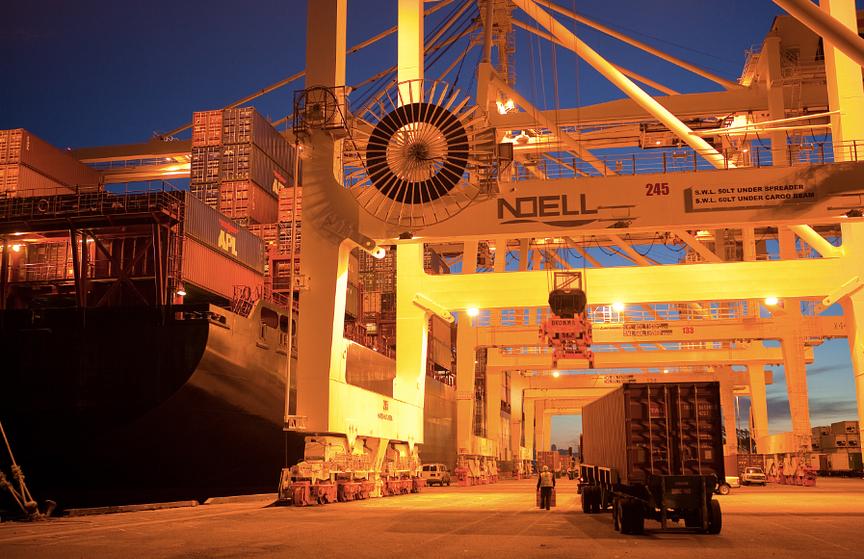
To understand the business impact of these technical failure modes, let us look at a realistic engineering narrative based on common occurrences at major container terminals.
Consider a high-throughput terminal in the Arabian Gulf operating a mega-max STS crane. To hit vessel turnaround targets, the crane operates at high gantry speeds. Over time, environmental heat breaks down the elasticity of the cable jacket, and subtle timing misalignments develop in the reeling motor drive system.
First, during a rapid gantry acceleration phase, the reeling system experiences a sharp tension spike. Because the cable's tensile strength is insufficient for these cumulative loads, the internal reinforcement layer stretches past its elastic limit.
Second, the tensile load shifts completely onto the soft Class 5 copper conductor bundle. The conductors begin to elongate and fail to snap back to their original length.
Third, as the copper stretches, the internal insulation thins out and cracks under the strain. Simultaneously, the outer rubber sheath undergoes severe stress deformation and tears open.
Fourth, the open tear is immediately exposed to the harsh local environment—saline humidity and fine abrasive dust. Desert sand wedges into the core, acting as an internal abrasive during subsequent winding cycles.
Fifth, during a critical vessel discharge operation, a phase-to-ground short circuit occurs inside the cable. The crane loses power instantly, leaving a container suspended over the ship.
The Business Impact
For a port technical director, this engineering chain reaction results in a major financial hit. Replacing a high-voltage STS reeling cable requires specialized tracking equipment, testing, and days of labor. More importantly, the unexpected downtime of a primary berth crane can cost thousands of dollars per hour in port penalties and vessel delays, severely impacting the terminal’s efficiency and regional reputation.
10. Selection Checklist for Port Engineers
When specifying or procuring replacement reeling cables for STS cranes, engineers should treat the cable as an integrated component of a larger mechanical system, rather than a standalone commodity. PEMA strongly recommends evaluating cable selection, installation methods, and reeling system design together.
Before approving a cable specification sheet, ensure the following parameters match the exact operating conditions of the crane:
Crane Travel Speed: Verify the cable's maximum rated operational velocity matches or exceeds the gantry's peak capability (typically 30 to 60 meters per minute).
Trolley Speed: Ensure the cable layout can withstand the structural vibrations transmitted by trolley movements up to 240 meters per minute.
Reeling Speed: Confirm the cable is rated for rapid winding synchronization speeds (100 to 200 meters per minute).
Travel Distance: Double-check that the cable's structural reinforcement can support its own weight over long travel runs exceeding 60 meters.
Required Tensile Load: Calculate the peak dynamic tension of the reel system and ensure it remains well within the cable's continuous tensile rating.
Minimum Bending Radius: Verify the reel drum diameter matches the cable manufacturer’s minimum dynamic bending radius guidelines (typically 12 to 15 times the cable diameter).
Cycle Life Requirement: Demand verified testing data showing the cable can survive hundreds of thousands of continuous winding cycles without structural failure.
Manufacturer Approval for Dynamic Loading: Ensure the manufacturer explicitly guarantees the specific model for heavy-duty, high-speed dynamic reeling under high ambient temperatures.
11. Why This Matters for STS Reliability
In the highly competitive maritime hubs of the Middle East, container terminal reliability is a primary competitive advantage. As port operators invest heavily in automation and high-speed infrastructure to handle the world's largest container vessels, the components supporting these operations must be exceptionally durable.
Optimizing tensile strength in STS crane reeling cables is a direct investment in asset uptime, operational safety, and maintenance predictability. Choosing a cable with premium aramid or steel reinforcements, compliant with VDE and IEC standards, significantly reduces the risk of unplanned breakdowns.
Ultimately, for modern port engineers, tensile strength is a critical lifecycle parameter. Specifying high-tensile, ruggedized reeling cables protects your cranes from structural failures, lowers total cost of ownership, and keeps your terminal operating smoothly.
Master Your Port Infrastructure
Are you experiencing premature cable tracking issues or insulation faults on your ultra-large STS cranes? Contact our technical engineering team today for a comprehensive calculation review of your current reeling system tension profiles. Let us help you select a robust, high-tensile cable solution tailored to withstand the demanding operating conditions of Middle Eastern ports.
Port crane cables | Mining cables | Reeling cables | Trailing cables | Festoon cables | Heavy-duty power cables | Medium voltage cables | Offshore crane cables | Underground mining cables | Dragline cables | Shearer cables | Container handling cables | STS crane cables | RTG cables | Mobile equipment cables | Armored cables | Flexible power cables | VFD cables | Submersible cables | Cold resistant cables | Abrasion resistant cables | Flame retardant cables | Marine environment cables | Opencast mining | Underground operations
© 2006 All rights reserved.
[INDUSTRIAL_CABLES]
INDUSTRIAL GRADE CABLE SYSTEMS | PORT & MINING SOLUTIONS
TEL: +86 153 7530 2641 |MAIL: hongjing.Wang@feichuncables.com